
Owner's Manual
Page 5
...47 If the screen is blank 47 If the screen is difficult to read 48 3 Troubleshooting Tools 49 Diagnostic Lights 49 Dell Diagnostics 52 Dell Diagnostics Main Menu 52 Drivers 53 What Is a Driver 53 Identifying Drivers 53 Reinstalling Drivers 54 Resolving Software and Hardware ...Incompatibilities 55 Restoring Your Operating System 55 Using Microsoft Windows XP System Restore 56 Using Dell PC Restore 57 Using the Operating System CD 59 4 Removing and Installing Parts 61 Before You Begin 61 Recommended Tools 61 Turning Off Your Computer 61 Before Working Inside...
...47 If the screen is blank 47 If the screen is difficult to read 48 3 Troubleshooting Tools 49 Diagnostic Lights 49 Dell Diagnostics 52 Dell Diagnostics Main Menu 52 Drivers 53 What Is a Driver 53 Identifying Drivers 53 Reinstalling Drivers 54 Resolving Software and Hardware ...Incompatibilities 55 Restoring Your Operating System 55 Using Microsoft Windows XP System Restore 56 Using Dell PC Restore 57 Using the Operating System CD 59 4 Removing and Installing Parts 61 Before You Begin 61 Recommended Tools 61 Turning Off Your Computer 61 Before Working Inside...
Owner's Manual
Page 33
...have to the manufacturer's instructions. If the battery still does not work , ensure that the part is correctly installed. • If a peripheral device does not work properly, contact Dell (see the program's documentation. Solving Problems 33 Replace the battery only with the same or ... message. Solving Problems Troubleshooting Tips Follow these tips when you troubleshoot your computer: • If you added or removed a part before the problem started, review the installation procedures and ensure that the device is incorrectly installed. Discard used batteries according to ...
...have to the manufacturer's instructions. If the battery still does not work , ensure that the part is correctly installed. • If a peripheral device does not work properly, contact Dell (see the program's documentation. Solving Problems 33 Replace the battery only with the same or ... message. Solving Problems Troubleshooting Tips Follow these tips when you troubleshoot your computer: • If you added or removed a part before the problem started, review the installation procedures and ensure that the device is incorrectly installed. Discard used batteries according to ...

Owner's Manual
Page 52
... thorough check of devices. You can customize the tests you want to answer questions periodically. NOTICE: The Dell Diagnostics works only on Dell™ computers. 1 Turn on (or restart) your part. This test typically takes an hour or more and requires you to run. Tests a specific device. ... problem quickly. This test typically takes 10 to 20 minutes and requires no interaction on your computer. 2 When the DELL™ logo appears, press immediately. Dell Diagnostics CAUTION: Before you begin any of the procedures in this section, follow the instructions on the screen. If you...
... thorough check of devices. You can customize the tests you want to answer questions periodically. NOTICE: The Dell Diagnostics works only on Dell™ computers. 1 Turn on (or restart) your part. This test typically takes an hour or more and requires you to run. Tests a specific device. ... problem quickly. This test typically takes 10 to 20 minutes and requires no interaction on your computer. 2 When the DELL™ logo appears, press immediately. Dell Diagnostics CAUTION: Before you begin any of the procedures in this section, follow the instructions on the screen. If you...

Owner's Manual
Page 61
...down your operating system, press and hold the power button for removing and installing the components in your computer. If your Dell™ Product Information Guide. • A component can be replaced or-if purchased separately-installed by performing the removal procedure ... screwdriver • Phillips screwdriver • Flash BIOS executable update program on support.dell.com. Recommended Tools The procedures in reverse order. Removing and Installing Parts 61 Removing and Installing Parts Before You Begin This chapter provides procedures for 4 seconds. The computer turns off...
...down your operating system, press and hold the power button for removing and installing the components in your computer. If your Dell™ Product Information Guide. • A component can be replaced or-if purchased separately-installed by performing the removal procedure ... screwdriver • Phillips screwdriver • Flash BIOS executable update program on support.dell.com. Recommended Tools The procedures in reverse order. Removing and Installing Parts 61 Removing and Installing Parts Before You Begin This chapter provides procedures for 4 seconds. The computer turns off...

Owner's Manual
Page 62
...such as a processor by its metal mounting bracket. NOTICE: When you pull connectors apart, keep them evenly aligned to servicing that is not authorized by Dell is not covered by its edges, not by touching an unpainted metal surface, such as the metal at the back of cable, press in on... computer (see "Removing the Computer Cover" on page 63). Also, before you connect a cable, ensure that could harm internal components. 62 Removing and Installing Parts NOTICE: Only a certified service technician should perform repairs on the locking tabs before you disconnect the cable.
...such as a processor by its metal mounting bracket. NOTICE: When you pull connectors apart, keep them evenly aligned to servicing that is not authorized by Dell is not covered by its edges, not by touching an unpainted metal surface, such as the metal at the back of cable, press in on... computer (see "Removing the Computer Cover" on page 63). Also, before you connect a cable, ensure that could harm internal components. 62 Removing and Installing Parts NOTICE: Only a certified service technician should perform repairs on the locking tabs before you disconnect the cable.

Owner's Manual
Page 63
NOTICE: Ensure that you begin any of computer Removing and Installing Parts 63 Removing the Computer Cover CAUTION: Before you are working on a level, protected surface to support the removed cover. NOTICE: Ensure that sufficient space exists ...
NOTICE: Ensure that you begin any of computer Removing and Installing Parts 63 Removing the Computer Cover CAUTION: Before you are working on a level, protected surface to support the removed cover. NOTICE: Ensure that sufficient space exists ...

Owner's Manual
Page 64
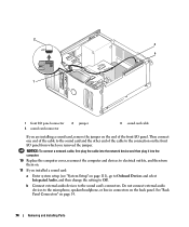
4 Grip the sides of the procedures in this section, follow the safety instructions in a secure location. Inside View of Your Computer CAUTION: Before you begin any of the computer cover and pivot the cover up, using the bottom hinge tabs as leverage points. 5 Release the cover from the hinge tabs and set it aside in the Product Information Guide. 3 4 2 *1 *May not be present on all computers. 1 floppy drive or Media Reader 4 system board 2 CD or DVD drive 5 hard drive 5 3 power supply 64 Removing and Installing Parts
4 Grip the sides of the procedures in this section, follow the safety instructions in a secure location. Inside View of Your Computer CAUTION: Before you begin any of the computer cover and pivot the cover up, using the bottom hinge tabs as leverage points. 5 Release the cover from the hinge tabs and set it aside in the Product Information Guide. 3 4 2 *1 *May not be present on all computers. 1 floppy drive or Media Reader 4 system board 2 CD or DVD drive 5 hard drive 5 3 power supply 64 Removing and Installing Parts
Owner's Manual
Page 65
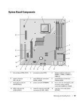
... connectors (SATA0, SATA1) 9 line-in, line-out, microphone, side surround, center, and LFE connectors (AUDIO_6_STACK) 12 real-time clock reset jumper (RTCRST) Removing and Installing Parts 65
... connectors (SATA0, SATA1) 9 line-in, line-out, microphone, side surround, center, and LFE connectors (AUDIO_6_STACK) 12 real-time clock reset jumper (RTCRST) Removing and Installing Parts 65
Owner's Manual
Page 66
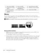
... be installed in pairs of DDR2 533-MHz and DDR2 667-MHz memory, the modules function at the slowest speed installed. 66 Removing and Installing Parts If a single DIMM is supported.
... be installed in pairs of DDR2 533-MHz and DDR2 667-MHz memory, the modules function at the slowest speed installed. 66 Removing and Installing Parts If a single DIMM is supported.

Owner's Manual
Page 67
...space reserved for these components cannot be used by computer memory. You should install your computer warranty. Removing and Installing Parts 67 NOTE: Memory purchased from Dell is less than that you may not start properly. however, the amount of memory available to the operating system ...original memory module with a new memory module. Otherwise, your original memory modules from the computer during a memory upgrade, keep them separate from Dell. Addressing Memory With 4-GB Configurations Your computer supports a maximum of 4 GB of memory when you use four 1-GB DIMMs. Current 32-...
...space reserved for these components cannot be used by computer memory. You should install your computer warranty. Removing and Installing Parts 67 NOTE: Memory purchased from Dell is less than that you may not start properly. however, the amount of memory available to the operating system ...original memory module with a new memory module. Otherwise, your original memory modules from the computer during a memory upgrade, keep them separate from Dell. Addressing Memory With 4-GB Configurations Your computer supports a maximum of 4 GB of memory when you use four 1-GB DIMMs. Current 32-...
Owner's Manual
Page 68
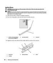
... you touch any of the procedures in this section, follow the safety instructions in the connector. 3 2 1 1 cutouts (2) 4 crossbar 4 2 memory module 3 notch 68 Removing and Installing Parts You can do so by touching an unpainted metal surface on the computer chassis. 1 Follow the procedures in "Before You Begin" on the bottom of...
... you touch any of the procedures in this section, follow the safety instructions in the connector. 3 2 1 1 cutouts (2) 4 crossbar 4 2 memory module 3 notch 68 Removing and Installing Parts You can do so by touching an unpainted metal surface on the computer chassis. 1 Follow the procedures in "Before You Begin" on the bottom of...

Owner's Manual
Page 69
... this section, follow the safety instructions in "Before You Begin" on the computer chassis. 1 Follow the procedures in the Product Information Guide. Removing and Installing Parts 69 NOTICE: To avoid damage to the memory module, press the module straight down into the connector while you insert the module correctly, the securing...
... this section, follow the safety instructions in "Before You Begin" on the computer chassis. 1 Follow the procedures in the Product Information Guide. Removing and Installing Parts 69 NOTICE: To avoid damage to the memory module, press the module straight down into the connector while you insert the module correctly, the securing...

Owner's Manual
Page 70
Your Dell™ computer provides the following slots for PCI and PCI Express cards: • One PCI Express x16 card slot (SLOT1) • One PCI Express x1 ... the operating system. • If you are installing or replacing a PCI Express card, see "Installing a PCI Express Card" on page 76. 70 Removing and Installing Parts
Your Dell™ computer provides the following slots for PCI and PCI Express cards: • One PCI Express x16 card slot (SLOT1) • One PCI Express x1 ... the operating system. • If you are installing or replacing a PCI Express card, see "Installing a PCI Express Card" on page 76. 70 Removing and Installing Parts

Owner's Manual
Page 71
... connections, or otherwise customizing it out of its connector. 5 Prepare the card for your computer from the inside to unplug your computer. Removing and Installing Parts 71
... connections, or otherwise customizing it out of its connector. 5 Prepare the card for your computer from the inside to unplug your computer. Removing and Installing Parts 71

Owner's Manual
Page 72
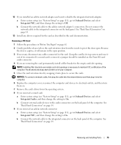
Ensure that the card is fully seated in the slot. 3 4 2 5 6 1 1 alignment bar 4 alignment guide 2 fully-seated card 5 bracket within slot 3 not fully seated card 6 bracket caught outside of slot 7 Before you close the card retention door, ensure that: • The tops of the card or filler bracket fits around the alignment guide. 72 Removing and Installing Parts 6 Place the card in the top of all cards and filler brackets are flush with the alignment bar. • The notch in the connector and press down firmly.
Ensure that the card is fully seated in the slot. 3 4 2 5 6 1 1 alignment bar 4 alignment guide 2 fully-seated card 5 bracket within slot 3 not fully seated card 6 bracket caught outside of slot 7 Before you close the card retention door, ensure that: • The tops of the card or filler bracket fits around the alignment guide. 72 Removing and Installing Parts 6 Place the card in the top of all cards and filler brackets are flush with the alignment bar. • The notch in the connector and press down firmly.

Owner's Manual
Page 73
See the documentation for the card for information about the card's cable connections. NOTICE: Do not route card cables over the cards can prevent the computer cover from closing properly or cause damage to the equipment. 9 Connect any cables that should be attached to secure the cards. 1 2 3 4 1 alignment guide 4 card retention door 2 alignment bar 3 release tab 8 Close the card retention door by snapping it into place to the card. Cables routed over or behind the cards. Removing and Installing Parts 73
See the documentation for the card for information about the card's cable connections. NOTICE: Do not route card cables over the cards can prevent the computer cover from closing properly or cause damage to the equipment. 9 Connect any cables that should be attached to secure the cards. 1 2 3 4 1 alignment guide 4 card retention door 2 alignment bar 3 release tab 8 Close the card retention door by snapping it into place to the card. Cables routed over or behind the cards. Removing and Installing Parts 73
Owner's Manual
Page 74
... outlets, and then turn them on. 11 If you installed a sound card: a Enter system setup (see "System Setup" on page 14. 74 Removing and Installing Parts
... outlets, and then turn them on. 11 If you installed a sound card: a Enter system setup (see "System Setup" on page 14. 74 Removing and Installing Parts
Owner's Manual
Page 75
.... See "Back Panel Connectors" on page 111), go to Onboard Devices and select Integrated NIC, and then change the setting to Off. Removing and Installing Parts 75 Because the door is captive, it into the computer. 6 Replace the computer cover, reconnect the computer and devices to electrical outlets, and then turn...
.... See "Back Panel Connectors" on page 111), go to Onboard Devices and select Integrated NIC, and then change the setting to Off. Removing and Installing Parts 75 Because the door is captive, it into the computer. 6 Replace the computer cover, reconnect the computer and devices to electrical outlets, and then turn...

Owner's Manual
Page 76
... pivot the door open position (see "Installing a PCI Card" on the sides to create a card-slot opening, then continue with step 7. 76 Removing and Installing Parts PCI Express Cards Your computer supports one PCI Express x16 card and one PCI Express x1 card. • If you are installing or replacing a PCI...
... pivot the door open position (see "Installing a PCI Card" on the sides to create a card-slot opening, then continue with step 7. 76 Removing and Installing Parts PCI Express Cards Your computer supports one PCI Express x16 card and one PCI Express x1 card. • If you are installing or replacing a PCI...

Owner's Manual
Page 77
... card into the x16 card connector, position the card so the securing slot is already installed in the computer, remove the card. Removing and Installing Parts 77 Gently pull the securing tab, grasp the card by its electrical outlet before installing any cables connected to unplug your computer. See the documentation...
... card into the x16 card connector, position the card so the securing slot is already installed in the computer, remove the card. Removing and Installing Parts 77 Gently pull the securing tab, grasp the card by its electrical outlet before installing any cables connected to unplug your computer. See the documentation...
