
Owner's Manual
Page 1
Dell™ Dimension™ E521 Owner's Manual Service Tag CD or DVD eject button CD or DVD activity light FlexBay for optional floppy drive or Media Card Reader microphone connector headphone connector diagnostic lights hard-drive activity light power button/ power activity light USB 2.0 connectors (2) cover latch release Model DCSM www.dell.com | support.dell.com
Dell™ Dimension™ E521 Owner's Manual Service Tag CD or DVD eject button CD or DVD activity light FlexBay for optional floppy drive or Media Card Reader microphone connector headphone connector diagnostic lights hard-drive activity light power button/ power activity light USB 2.0 connectors (2) cover latch release Model DCSM www.dell.com | support.dell.com

Owner's Manual
Page 5
... Problems 47 If the screen is blank 47 If the screen is difficult to read 48 3 Troubleshooting Tools 49 Diagnostic Lights 49 Dell Diagnostics 52 Dell Diagnostics Main Menu 52 Drivers 53 What Is a Driver 53 Identifying Drivers 53 Reinstalling Drivers 54 Resolving Software and Hardware ...Incompatibilities 55 Restoring Your Operating System 55 Using Microsoft Windows XP System Restore 56 Using Dell PC Restore 57 Using the Operating System CD 59 4 Removing and Installing Parts 61 Before You Begin 61 Recommended Tools 61 ...
... Problems 47 If the screen is blank 47 If the screen is difficult to read 48 3 Troubleshooting Tools 49 Diagnostic Lights 49 Dell Diagnostics 52 Dell Diagnostics Main Menu 52 Drivers 53 What Is a Driver 53 Identifying Drivers 53 Reinstalling Drivers 54 Resolving Software and Hardware ...Incompatibilities 55 Restoring Your Operating System 55 Using Microsoft Windows XP System Restore 56 Using Dell PC Restore 57 Using the Operating System CD 59 4 Removing and Installing Parts 61 Before You Begin 61 Recommended Tools 61 ...

Owner's Manual
Page 11
Press to eject a disk from the CD or DVD drive. See "Removing the Computer Cover" on when the computer reads data from the CD or DVD drive. Setting Up and Using Your Computer Front View of the Computer 1 2 3 4 5 6 7 8 9 10 11 12 1 cover latch release 2 location of Service Tag 3 CD or DVD eject button 4 CD or DVD activity light Use this latch to identify your computer when you access the Dell Support website or call technical support. Setting Up and Using Your Computer 11 The drive light is on page 63. Use the Service Tag to remove the cover.
Press to eject a disk from the CD or DVD drive. See "Removing the Computer Cover" on when the computer reads data from the CD or DVD drive. Setting Up and Using Your Computer Front View of the Computer 1 2 3 4 5 6 7 8 9 10 11 12 1 cover latch release 2 location of Service Tag 3 CD or DVD eject button 4 CD or DVD activity light Use this latch to identify your computer when you access the Dell Support website or call technical support. Setting Up and Using Your Computer 11 The drive light is on page 63. Use the Service Tag to remove the cover.
Owner's Manual
Page 12
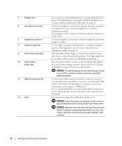
... and most kinds of this button indicates power state. 5 FlexBay drive 6 microphone connector 7 headphone connector 8 diagnostic lights (4) 9 hard-drive activity light 10 power button, power light 11 USB 2.0 connectors (2) 12 vents Can contain an optional floppy drive or optional Media Card Reader. Use the ... that there is operating. For more information, see "System Setup Options" on page 112 for bootable USB devices (see "Diagnostic Lights" on the computer. Press the power button to turn on page 49. Use the front USB connectors for devices that typically remain...
... and most kinds of this button indicates power state. 5 FlexBay drive 6 microphone connector 7 headphone connector 8 diagnostic lights (4) 9 hard-drive activity light 10 power button, power light 11 USB 2.0 connectors (2) 12 vents Can contain an optional floppy drive or optional Media Card Reader. Use the ... that there is operating. For more information, see "System Setup Options" on page 112 for bootable USB devices (see "Diagnostic Lights" on the computer. Press the power button to turn on page 49. Use the front USB connectors for devices that typically remain...

Owner's Manual
Page 14
... use the connector on the card. 14 Setting Up and Using Your Computer A high volume of network traffic may make this light appear to be in connector to attach a personal computer microphone for your network. A click indicates that you must use the ...broadband device. On computers with a sound card, the microphone connector is recommended that the network cable has been securely attached. Flashes a yellow light when the computer is not detecting a physical connection to ensure reliable operation. A good connection exists between a 10-Mbps network and the computer....
... use the connector on the card. 14 Setting Up and Using Your Computer A high volume of network traffic may make this light appear to be in connector to attach a personal computer microphone for your network. A click indicates that you must use the ...broadband device. On computers with a sound card, the microphone connector is recommended that the network cable has been securely attached. Flashes a yellow light when the computer is not detecting a physical connection to ensure reliable operation. A good connection exists between a 10-Mbps network and the computer....

Owner's Manual
Page 38
... until the computer turns off. E N S U R E T H A T T H E U S B P O R T S A R E E N A B L E D I G H T S - See "System Setup" on page 55. Connect a properly working keyboard to the computer, and try using the keyboard. See "Diagnostic Lights" on your keyboard or moving your computer. Then restart your mouse, press and hold the power button for at least 8 to perform an operating system...
... until the computer turns off. E N S U R E T H A T T H E U S B P O R T S A R E E N A B L E D I G H T S - See "System Setup" on page 55. Connect a properly working keyboard to the computer, and try using the keyboard. See "Diagnostic Lights" on your keyboard or moving your computer. Then restart your mouse, press and hold the power button for at least 8 to perform an operating system...

Owner's Manual
Page 42
... E N E T W O R K L I V E R - If the link integrity light is firmly inserted into both the network connector on page 109. Replace the network cable. RESTART THE ... press to display the Start menu. 2 Type u, press the keyboard arrow keys to the computer, and try using the mouse. For a description of network lights, see "Controls and Lights" on the back of the procedures in this section, follow the safety instructions in the Product Information Guide. R U N T H E H A R D W A R E TR O U B L E S H O O T E R - R E I N S T A L L T H E M O U S E D R I G H T S O N T H E B A...
... E N E T W O R K L I V E R - If the link integrity light is firmly inserted into both the network connector on page 109. Replace the network cable. RESTART THE ... press to display the Start menu. 2 Type u, press the keyboard arrow keys to the computer, and try using the mouse. For a description of network lights, see "Controls and Lights" on the back of the procedures in this section, follow the safety instructions in the Product Information Guide. R U N T H E H A R D W A R E TR O U B L E S H O O T E R - R E I N S T A L L T H E M O U S E D R I G H T S O N T H E B A...

Owner's Manual
Page 43
... cards (see "Cards" on page 70). • Remove and then reinstall the graphics card, if applicable (see "PCI Express Cards" on page 65). See "Diagnostic Lights" on the keyboard, move the mouse, or press the power button to the system board (see "System Board Components" on page 65). • Remove and...
... cards (see "Cards" on page 70). • Remove and then reinstall the graphics card, if applicable (see "PCI Express Cards" on page 65). See "Diagnostic Lights" on the keyboard, move the mouse, or press the power button to the system board (see "System Board Components" on page 65). • Remove and...
Owner's Manual
Page 46
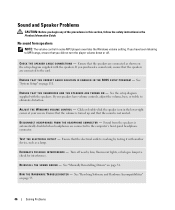
... is not muted. C H E C K T H E S P E A K E R C A B L E C O N N E C T I V E R - E N S U R E T H A T T H E C O R R E C T A U D I O S O L U T I O N I S E N A B L E D I N T H E B I S C O N N E C T H E A D P H O N E S F R O M T H E H E A D P H O N E C O N N E C T O R - See "Manually Reinstalling Drivers" on page 111. If you did not turn the player volume down or off nearby fans, fluorescent lights, or halogen lamps to the card. D I O S S E T U P P R O G R A M - Click or double-click the speaker icon in the lower-right corner of the procedures in this section, follow ...
... is not muted. C H E C K T H E S P E A K E R C A B L E C O N N E C T I V E R - E N S U R E T H A T T H E C O R R E C T A U D I O S O L U T I O N I S E N A B L E D I N T H E B I S C O N N E C T H E A D P H O N E S F R O M T H E H E A D P H O N E C O N N E C T O R - See "Manually Reinstalling Drivers" on page 111. If you did not turn the player volume down or off nearby fans, fluorescent lights, or halogen lamps to the card. D I O S S E T U P P R O G R A M - Click or double-click the speaker icon in the lower-right corner of the procedures in this section, follow ...

Owner's Manual
Page 47
..., firmly press the button to the card, rather than the video connector on the keyboard or move the mouse. If the power light is connected as a lamp. See "Diagnostic Lights" on page 11). Ensure that the monitor is securely inserted into the headphone connector (see "Front View of the Computer" on page..., check that the monitor cable is connected to ensure that the headphone cable is turned on the setup diagram for troubleshooting procedures. If the power light is blinking, press a key on the system board. • If you begin any of your computer. If the power...
..., firmly press the button to the card, rather than the video connector on the keyboard or move the mouse. If the power light is connected as a lamp. See "Diagnostic Lights" on page 11). Ensure that the monitor is securely inserted into the headphone connector (see "Front View of the Computer" on page..., check that the monitor cable is connected to ensure that the headphone cable is turned on the setup diagram for troubleshooting procedures. If the power light is blinking, press a key on the system board. • If you begin any of your computer. If the power...

Owner's Manual
Page 48
Fans, fluorescent lights, halogen lamps, and other electrical devices can cause the screen image to check for interference. If the screen is at least 60 cm (2 ft) away ...
Fans, fluorescent lights, halogen lamps, and other electrical devices can cause the screen image to check for interference. If the screen is at least 60 cm (2 ft) away ...
Owner's Manual
Page 49
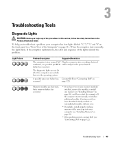
... section, follow the safety instructions in a normal "off" Plug the computer into your computer has four lights labeled "1," "2," "3," and "4" on the front panel (see "Contacting Dell" on page 11). page 122). If the computer malfunctions, the color and sequence of the Computer" on... • If the problem persists, contact Dell (see "Contacting Dell" on page 122). Troubleshooting Tools 49 failure has occurred. When the computer starts normally, the lights flash. A possible processor failure has Contact Dell (see "Front View of the lights identify the problem. Memory modules are not ...
... section, follow the safety instructions in a normal "off" Plug the computer into your computer has four lights labeled "1," "2," "3," and "4" on the front panel (see "Contacting Dell" on page 11). page 122). If the computer malfunctions, the color and sequence of the Computer" on... • If the problem persists, contact Dell (see "Contacting Dell" on page 122). Troubleshooting Tools 49 failure has occurred. When the computer starts normally, the lights flash. A possible processor failure has Contact Dell (see "Front View of the lights identify the problem. Memory modules are not ...

Owner's Manual
Page 50
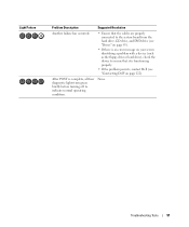
... error exists. • If you know works and restart the computer. • If the problem persists or the computer has integrated graphics, contact Dell (see "Contacting Dell" on page 122). Light Pattern Problem Description A possible graphics card failure has occurred. Reseat all modules without error. • If available, install properly working memory of...
... error exists. • If you know works and restart the computer. • If the problem persists or the computer has integrated graphics, contact Dell (see "Contacting Dell" on page 122). Light Pattern Problem Description A possible graphics card failure has occurred. Reseat all modules without error. • If available, install properly working memory of...
Owner's Manual
Page 51
...drive, CD drive, and DVD drive (see "Contacting Dell" on your screen identifying a problem with a device (such as the floppy drive or hard drive), check the device to ensure that it is complete, all four diagnostic lights turn green briefly before turning off to indicate normal operating ...condition. Troubleshooting Tools 51 After POST is functioning properly. • If the problem persists, contact Dell (see "Drives" on page 85). • If there is...
...drive, CD drive, and DVD drive (see "Contacting Dell" on your screen identifying a problem with a device (such as the floppy drive or hard drive), check the device to ensure that it is complete, all four diagnostic lights turn green briefly before turning off to indicate normal operating ...condition. Troubleshooting Tools 51 After POST is functioning properly. • If the problem persists, contact Dell (see "Drives" on page 85). • If there is...
Owner's Manual
Page 109
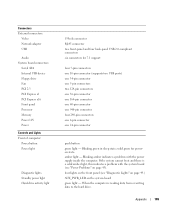
... there is reading data from or writing data to the hard drive. four lights on the front panel (see "Power Problems" on the system board green light - When the computer is a solid amber light, this indicates a problem with the power supply inside the computer. Connectors External... 2.3 PCI Express x1 PCI Express x16 Front panel Processor Memory Power 12V Power Controls and Lights Front of computer: Power button Power light Diagnostic lights Standby power light Hard-drive activity light 15-hole connector RJ-45 connector two front-panel and four back-panel USB 2.0-compliant connectors...
... there is reading data from or writing data to the hard drive. four lights on the front panel (see "Power Problems" on the system board green light - When the computer is a solid amber light, this indicates a problem with the power supply inside the computer. Connectors External... 2.3 PCI Express x1 PCI Express x16 Front panel Processor Memory Power 12V Power Controls and Lights Front of computer: Power button Power light Diagnostic lights Standby power light Hard-drive activity light 15-hole connector RJ-45 connector two front-panel and four back-panel USB 2.0-compliant connectors...

Owner's Manual
Page 110
...: Heat dissipation is not detecting a physical connection to 80% (noncondensing) 110 Appendix A good connection exists between a 100 Mbps network and the computer. off (no light) - A good connection exists between a 10 Mbps network and the computer. Voltage (see the safety instructions 90 to 135 V and 180 to 265 V at 50... 35°C (50° to 95°F) -40° to 65°C (-40° to 149°F) 20% to the network. Controls and Lights (continued) Rear of computer: Link integrity light (on integrated network adapter) Network activity light (on integrated network adapter) green...
...: Heat dissipation is not detecting a physical connection to 80% (noncondensing) 110 Appendix A good connection exists between a 100 Mbps network and the computer. off (no light) - A good connection exists between a 10 Mbps network and the computer. Voltage (see the safety instructions 90 to 135 V and 180 to 265 V at 50... 35°C (50° to 95°F) -40° to 65°C (-40° to 149°F) 20% to the network. Controls and Lights (continued) Rear of computer: Link integrity light (on integrated network adapter) Network activity light (on integrated network adapter) green...

Owner's Manual
Page 119
... water and one part dishwashing detergent. If possible, use liquid or aerosol cleaners, which may damage the antiglare coating. • To clean your monitor screen, lightly dampen a soft, clean cloth with a brush attachment to gently remove dust from the slots and holes on your computer and from the electrical outlet. Appendix...
... water and one part dishwashing detergent. If possible, use liquid or aerosol cleaners, which may damage the antiglare coating. • To clean your monitor screen, lightly dampen a soft, clean cloth with a brush attachment to gently remove dust from the slots and holes on your computer and from the electrical outlet. Appendix...
Owner's Manual
Page 120
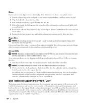
... motion around the disc. 2 With a soft, lint-free cloth, gently wipe the bottom of the computer and all Dell-installed hardware. Dell Technical Support Policy (U.S. Floppy Drive NOTICE: Do not attempt to the original default configuration as the verification of appropriate functionality ...of the disc (the unlabeled side) in their channels if they are dirty, clean the rollers with a cotton swab moistened lightly with...
... motion around the disc. 2 With a soft, lint-free cloth, gently wipe the bottom of the computer and all Dell-installed hardware. Dell Technical Support Policy (U.S. Floppy Drive NOTICE: Do not attempt to the original default configuration as the verification of appropriate functionality ...of the disc (the unlabeled side) in their channels if they are dirty, clean the rollers with a cotton swab moistened lightly with...

Owner's Manual
Page 145
... or floppy disk available. An interface for a SATA hard drive Host Controller which allows the storage driver to enable technologies such as system setup. ambient light sensor - alert standards format - battery operating time - The smallest unit of the devices from your computer. Specifies the order of data interpreted by your particular...
... or floppy disk available. An interface for a SATA hard drive Host Controller which allows the storage driver to enable technologies such as system setup. ambient light sensor - alert standards format - battery operating time - The smallest unit of the devices from your computer. Specifies the order of data interpreted by your particular...

Owner's Manual
Page 149
... such as digital cameras and DVD players, to connect IEEE 1394-compatible devices, such as optical drives, a second battery, or a Dell TravelLite™ module. Also referred to as a serial connector, parallel connector, or expansion slot) and allows the processor to communicate with... a specific device (such as built-in. K Kb - An electronic component that emits light to the Internet, send and receive e-mail, and access websites. The designation for infrared communications. integrated device electronics - An operation ...
... such as digital cameras and DVD players, to connect IEEE 1394-compatible devices, such as optical drives, a second battery, or a Dell TravelLite™ module. Also referred to as a serial connector, parallel connector, or expansion slot) and allows the processor to communicate with... a specific device (such as built-in. K Kb - An electronic component that emits light to the Internet, send and receive e-mail, and access websites. The designation for infrared communications. integrated device electronics - An operation ...