Service Manual
Page 2
... 4.4.1 Panel Feature 11 4.4.2 Display Characteristics 11 4.4.3 Optical Characteristics 12 4.4.4 Parameter guide line for CCFL Inverter 12 5. MONITOR SPECIFICATIONS 4 2. Block Diagram 13 5.1 Monitor Exploded View 13 5.2 Software Flow Chart 14 5.3 Electrical Block Diagram 16 5.3.1 Main Board 16 5.3.2 Inverter/Power Board 17 6. OPERATING INSTRUCTIONS 6 3.1 GENERAL INSTRUCTIONS 6 3.2 CONTROL BUTTONS 6 3.3 ADJUSTING THE PICTURE 7 4. LCD MONITOR DESCRIPTION 5 3. Schematic 18 6.1 Main Board 18 6.2 Inverter/Power Board 23 2
... 4.4.1 Panel Feature 11 4.4.2 Display Characteristics 11 4.4.3 Optical Characteristics 12 4.4.4 Parameter guide line for CCFL Inverter 12 5. MONITOR SPECIFICATIONS 4 2. Block Diagram 13 5.1 Monitor Exploded View 13 5.2 Software Flow Chart 14 5.3 Electrical Block Diagram 16 5.3.1 Main Board 16 5.3.2 Inverter/Power Board 17 6. OPERATING INSTRUCTIONS 6 3.1 GENERAL INSTRUCTIONS 6 3.2 CONTROL BUTTONS 6 3.3 ADJUSTING THE PICTURE 7 4. LCD MONITOR DESCRIPTION 5 3. Schematic 18 6.1 Main Board 18 6.2 Inverter/Power Board 23 2
Service Manual
Page 3
EDIT Content 38 11. Executing ISP 43 12. ISP User Manual 39 11.1. Connect ISP Writer preparation action 39 11.2. White-Balance, Luminance adjustment 36 10. BOM List 44 3 PCB Layout 25 7.1 Main Board 25 7.2 Inverter/Power Board 26 7.3 Keypad Board 28 8. DELL E173FP Service Manual 7. Maintainability 29 8.1 Equipments and Tools Requirements 29 8.2 Trouble Shooting 30 8.2.1 Main Board 30 8.2.2 Power/Inverter Board 33 8.2.3 Key Pad Board 35 9. To Use ISP WRITER 39 11.3.
EDIT Content 38 11. Executing ISP 43 12. ISP User Manual 39 11.1. Connect ISP Writer preparation action 39 11.2. White-Balance, Luminance adjustment 36 10. BOM List 44 3 PCB Layout 25 7.1 Main Board 25 7.2 Inverter/Power Board 26 7.3 Keypad Board 28 8. DELL E173FP Service Manual 7. Maintainability 29 8.1 Equipments and Tools Requirements 29 8.2 Trouble Shooting 30 8.2.1 Main Board 30 8.2.2 Power/Inverter Board 33 8.2.3 Key Pad Board 35 9. To Use ISP WRITER 39 11.3.
Service Manual
Page 5
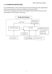
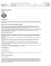
LCD MONITOR DESCRIPTION DELL E173FP Service Manual The LCD MONITOR will drive the backlight of panel and the DC-DC conversion. The internal Inverter/power board will contain a main board, an internal inverter/power board, keypad board, which house the flat panel control logic, brightness control logic and DDC. and provides the 12V DC-power to main board. 2. Monitor Block Diagram CCFT Driver. Flat Panel and CCFL backlight Inverter/Power Board AC Power IN Main Board Keyboard RS232 Connector For white balance adjustment in factory mode HOST Computer Video signal, DDC 5
LCD MONITOR DESCRIPTION DELL E173FP Service Manual The LCD MONITOR will drive the backlight of panel and the DC-DC conversion. The internal Inverter/power board will contain a main board, an internal inverter/power board, keypad board, which house the flat panel control logic, brightness control logic and DDC. and provides the 12V DC-power to main board. 2. Monitor Block Diagram CCFT Driver. Flat Panel and CCFL backlight Inverter/Power Board AC Power IN Main Board Keyboard RS232 Connector For white balance adjustment in factory mode HOST Computer Video signal, DDC 5

Service Manual
Page 20
DELL E173FP Service Manual +5V +5V +5V 3 5 6 7 8 2 KEY _MENU 2 KEY _RIGHT 2 KEY _LEFT 2 KEY _ONOFF KEY _MENU KEY _RIGHT KEY _LEFT KEY _ONOFF 4 3 2 1 RP103 4.7K 1/16W 2 LED_O ... LED_G 1 4.7K 1/16W Q102 PMBS3904 2 Q101 PMBS3904 CN101 2 R157 R158 R159 R160 220 1/16W 220 1/16W 220 1/16W 220 1/16W LED_GREEN 8 LED_ORANGE 7 6 ENTER 5 RIGHT 4 LEFT 3 POWER 2 1 To keyboard C154 C156 C155 0.001uF0.001uF 0.001uF C157 0.001uF GND GND GND GND C152 0.001uF GND C153 0.001uF GND GND CONN Title Size A Date...
DELL E173FP Service Manual +5V +5V +5V 3 5 6 7 8 2 KEY _MENU 2 KEY _RIGHT 2 KEY _LEFT 2 KEY _ONOFF KEY _MENU KEY _RIGHT KEY _LEFT KEY _ONOFF 4 3 2 1 RP103 4.7K 1/16W 2 LED_O ... LED_G 1 4.7K 1/16W Q102 PMBS3904 2 Q101 PMBS3904 CN101 2 R157 R158 R159 R160 220 1/16W 220 1/16W 220 1/16W 220 1/16W LED_GREEN 8 LED_ORANGE 7 6 ENTER 5 RIGHT 4 LEFT 3 POWER 2 1 To keyboard C154 C156 C155 0.001uF0.001uF 0.001uF C157 0.001uF GND GND GND GND C152 0.001uF GND C153 0.001uF GND GND CONN Title Size A Date...
Service Manual
Page 23
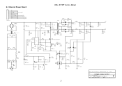
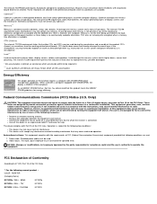
6.2 Internal Power Board C0N102 12 11 10 9 8 7 6 5 4 3 2 1 GND GND 5V 5V GND GND 12V 12V DIM GND ON/OFF GND 33A8009-12G-H 5V 12V DIM ON/OFF GND +4 DB901 2KBP06M 1 3 + C904 120uF/400V 2- 2 3 L902 73L-174-26-T 1 4 C907 0.1uF DELL E173FP Service Manual R906 1M 1/4W R907 1M 1/4W T901 1 O 9 R904 1M 1/4W... 0 1/4W R926 1K 1/4W C928 0.01uF R922 33K 1/4W R923 3.6K 1/4W R924 2.4K 1/4W CN901 AOC (Top Victory) Electronics Co., Ltd. Title 1.POWER 12V&5V OUTPUT Size Document Number PWPC1742LGD1(715L-1283-1) Date: Tuesday, March 16, 2004 Sheet 2 of Rev A 2 23
6.2 Internal Power Board C0N102 12 11 10 9 8 7 6 5 4 3 2 1 GND GND 5V 5V GND GND 12V 12V DIM GND ON/OFF GND 33A8009-12G-H 5V 12V DIM ON/OFF GND +4 DB901 2KBP06M 1 3 + C904 120uF/400V 2- 2 3 L902 73L-174-26-T 1 4 C907 0.1uF DELL E173FP Service Manual R906 1M 1/4W R907 1M 1/4W T901 1 O 9 R904 1M 1/4W... 0 1/4W R926 1K 1/4W C928 0.01uF R922 33K 1/4W R923 3.6K 1/4W R924 2.4K 1/4W CN901 AOC (Top Victory) Electronics Co., Ltd. Title 1.POWER 12V&5V OUTPUT Size Document Number PWPC1742LGD1(715L-1283-1) Date: Tuesday, March 16, 2004 Sheet 2 of Rev A 2 23

Service Manual
Page 29
... relative OK, input Normal Measured Crystal X101 OK, clock normal Replace U102 (GMZan3SL) Re-do "WHITE-Balance" 29 DELL E173FP Service Manual No DC Level Check Power board, is show Led Orange Connected the Signal cable again, Check LED status. Check Correspondent component Yes, all DC level ...No, nothing is there DC level output?. Is there any shortage or cold solder or PCB trace is in Power-on status, and check if Power switch had been stuck? 8.2 Trouble Shooting 8.2.1 Main Board 1) No display Measured CN104 pin 5 = 5 V? Check U105 pin3=5V, P105 pin2=3.3V? There have...
... relative OK, input Normal Measured Crystal X101 OK, clock normal Replace U102 (GMZan3SL) Re-do "WHITE-Balance" 29 DELL E173FP Service Manual No DC Level Check Power board, is show Led Orange Connected the Signal cable again, Check LED status. Check Correspondent component Yes, all DC level ...No, nothing is there DC level output?. Is there any shortage or cold solder or PCB trace is in Power-on status, and check if Power switch had been stuck? 8.2 Trouble Shooting 8.2.1 Main Board 1) No display Measured CN104 pin 5 = 5 V? Check U105 pin3=5V, P105 pin2=3.3V? There have...
Service Manual
Page 30
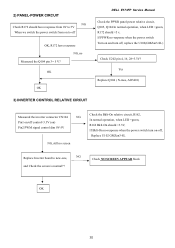
OK OK 3) INVERTER CONTROL RELATIVE CIRCUIT DELL E173FP Service Manual Check the PPWR panel power relative circuit, Q105, Q104 In normal operation, when LED =green, R172 should =5 v, If PPWR no-response when the power switch Turn on and turn on-off , replace the U102(GMZan3-SL) Check U202 pin 4, 16, 28=3.3V? Yes ...APPEAR block OK 30 2) PANEL-POWER CIRCUIT NG Check R172 should have response from 0V to 5V When we switch the power switch from on to off OK, R172 have response NG, no -response when the power switch turn off , Replace U102 GMZan3-SL Replace Inverter board to new-one, NG and ...
OK OK 3) INVERTER CONTROL RELATIVE CIRCUIT DELL E173FP Service Manual Check the PPWR panel power relative circuit, Q105, Q104 In normal operation, when LED =green, R172 should =5 v, If PPWR no-response when the power switch Turn on and turn on-off , replace the U102(GMZan3-SL) Check U202 pin 4, 16, 28=3.3V? Yes ...APPEAR block OK 30 2) PANEL-POWER CIRCUIT NG Check R172 should have response from 0V to 5V When we switch the power switch from on to off OK, R172 have response NG, no -response when the power switch turn off , Replace U102 GMZan3-SL Replace Inverter board to new-one, NG and ...
Service Manual
Page 32
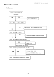
8.2.2 Power/Inverter Board 1.) No power DELL E173FP Service Manual Check to CN102 Pin9 and pin10 = 5V NG OK Check AC line volt 120V or 220V Check Interface board NG Change F901 , check BD901,Q903,IC901 OK Check the voltage of C904(+) NG OK Check bridge rectified circuit cFailure point Check start voltage for the pin3 of IC901 NG Change IC901 Repeating the start voltage Check the auxiliary voltage is smaller than 20V OK NG 1) Check IC902, IC903 2) Check Q901,Q902...OVP circuit Check R919, D910,D911,D912,D913, ZD904 32
8.2.2 Power/Inverter Board 1.) No power DELL E173FP Service Manual Check to CN102 Pin9 and pin10 = 5V NG OK Check AC line volt 120V or 220V Check Interface board NG Change F901 , check BD901,Q903,IC901 OK Check the voltage of C904(+) NG OK Check bridge rectified circuit cFailure point Check start voltage for the pin3 of IC901 NG Change IC901 Repeating the start voltage Check the auxiliary voltage is smaller than 20V OK NG 1) Check IC902, IC903 2) Check Q901,Q902...OVP circuit Check R919, D910,D911,D912,D913, ZD904 32

Service Manual
Page 43
...1 PCS 12 CM 1 PCS 1 PCS 1 PCS 1 PCS 1 PCS 1 PCS 1 PCS 4 PCS 5 PCS 3 PCS 43 12. Bill Of Material List DELL E173FP Service Manual Location Part Number CBPC780KGLDD KEPC780KED1 PWPC1742LGD1 11L6036 1 15L8054 2 23L3178700 1A 33L4669 GV C 33L4670 GV T 34L1367AY2 T 34L1368 Y2 T 40L 152509 40L 152512 40L 154501...Description CONVERSION BOARD KEY BOARD POWER BOARD SPACER SUPPORT SCC-24 MAIN FRAME LOGO POWER BUTTON KEY PAD BEZEL REAR COVER RECYCLE LABEL RECYCLE LABEL HI-POT ID LABEL DELL S/N LABEL SHIPPING LABEL CARTON LABEL QSG EPS EPS CARTON SPACE PAPER BARCODE RIBBOR PE BAG FOR MONITOR SMALL TAPE...
...1 PCS 12 CM 1 PCS 1 PCS 1 PCS 1 PCS 1 PCS 1 PCS 1 PCS 4 PCS 5 PCS 3 PCS 43 12. Bill Of Material List DELL E173FP Service Manual Location Part Number CBPC780KGLDD KEPC780KED1 PWPC1742LGD1 11L6036 1 15L8054 2 23L3178700 1A 33L4669 GV C 33L4670 GV T 34L1367AY2 T 34L1368 Y2 T 40L 152509 40L 152512 40L 154501...Description CONVERSION BOARD KEY BOARD POWER BOARD SPACER SUPPORT SCC-24 MAIN FRAME LOGO POWER BUTTON KEY PAD BEZEL REAR COVER RECYCLE LABEL RECYCLE LABEL HI-POT ID LABEL DELL S/N LABEL SHIPPING LABEL CARTON LABEL QSG EPS EPS CARTON SPACE PAPER BARCODE RIBBOR PE BAG FOR MONITOR SMALL TAPE...

Service Manual
Page 48
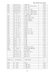
DELL E173FP Service Manual D104 93L 39146 LL5232B SMT 0 PCS D107 93L 39146 LL5232B SMT 0 PCS D108 93L 39146 LL5232B SMT 0 PCS D109 93L 39146 LL5232B SMT 0 PCS D111 93L 39146 LL5232B SMT 0 PCS D112 93L 39146 LL5232B SMT 0 PCS D102 93L 39149 MLL5232B BY FULL POWER 1 PCS D103... 1 PCS DP101 81L 12 1A GP LED 1 PCS CN101 95L8014 8 10 WURE HARNESS 1 PCS 715L1153 1A PCB 1 PCS PARENT NO: PWPC1742LGD1 POWER BOARD PW1742LGD1AI POWER BOARD 1 PCS PW1742LGD1SMT POWER BOARD 1 PCS CON201 33L8021 2D E WAFER 0 PCS CON202 33L8021 2D E WAFER 0 PCS 48
DELL E173FP Service Manual D104 93L 39146 LL5232B SMT 0 PCS D107 93L 39146 LL5232B SMT 0 PCS D108 93L 39146 LL5232B SMT 0 PCS D109 93L 39146 LL5232B SMT 0 PCS D111 93L 39146 LL5232B SMT 0 PCS D112 93L 39146 LL5232B SMT 0 PCS D102 93L 39149 MLL5232B BY FULL POWER 1 PCS D103... 1 PCS DP101 81L 12 1A GP LED 1 PCS CN101 95L8014 8 10 WURE HARNESS 1 PCS 715L1153 1A PCB 1 PCS PARENT NO: PWPC1742LGD1 POWER BOARD PW1742LGD1AI POWER BOARD 1 PCS PW1742LGD1SMT POWER BOARD 1 PCS CON201 33L8021 2D E WAFER 0 PCS CON202 33L8021 2D E WAFER 0 PCS 48
Service Manual
Page 50
DELL E173FP Service Manual C923 67L215C102 3K 1000UF/16V 0 PCS C904 67L215S10115H 100UF 450V 18*36 105 BY 0 PCS C904 67L215S10115K 100UF 450V 0 PCS C904 67L215S10115N 100UF+-...'Y 1 PCS 705L 560 61 05 R917 ASS'Y 1 PCS 705L 560 61 06 R903 ASS'Y 1 PCS 705L 780 57 DL Q903 ASS'Y 1 PCS PARENT NO: PW1742LGD1AI POWER BOARD CN901 6L 31500 EYELET 2 PCS C213 6L 31502 1.5MM RIVET 2 PCS C214 6L 31502 1.5MM RIVET 2 PCS C904 6L 31502 1.5MM RIVET 2 PCS 50
DELL E173FP Service Manual C923 67L215C102 3K 1000UF/16V 0 PCS C904 67L215S10115H 100UF 450V 18*36 105 BY 0 PCS C904 67L215S10115K 100UF 450V 0 PCS C904 67L215S10115N 100UF+-...'Y 1 PCS 705L 560 61 05 R917 ASS'Y 1 PCS 705L 560 61 06 R903 ASS'Y 1 PCS 705L 780 57 DL Q903 ASS'Y 1 PCS PARENT NO: PW1742LGD1AI POWER BOARD CN901 6L 31500 EYELET 2 PCS C213 6L 31502 1.5MM RIVET 2 PCS C214 6L 31502 1.5MM RIVET 2 PCS C904 6L 31502 1.5MM RIVET 2 PCS 50

Service Manual
Page 51
... 61L 17210252T 61L 17210252T 61L 17210252T 61L 17210252T 61L 17210252T 61L 17210252T 61L 17210252T 61L 17210252T 61L 17210252T DELL E173FP Service Manual 1.5MM RIVET 4 PCS 1.5MM RIVET 2 PCS 1.5MM RIVET 2 PCS 1.5MM RIVET 4 PCS POWER BOARD 1 PCS TIN COATED 0 PCS TIN COATED 0 PCS TIN COATED 0 PCS TIN COATED 0 PCS TIN COATED 0 PCS TIN COATED...
... 61L 17210252T 61L 17210252T 61L 17210252T 61L 17210252T 61L 17210252T 61L 17210252T 61L 17210252T 61L 17210252T 61L 17210252T DELL E173FP Service Manual 1.5MM RIVET 4 PCS 1.5MM RIVET 2 PCS 1.5MM RIVET 2 PCS 1.5MM RIVET 4 PCS POWER BOARD 1 PCS TIN COATED 0 PCS TIN COATED 0 PCS TIN COATED 0 PCS TIN COATED 0 PCS TIN COATED 0 PCS TIN COATED...

Service Manual
Page 53
DELL E173FP Service Manual C223 67L215C1514HT LOW ESR 150UF 25V 8*7MM 1 PCS C924 67L215N4713NT EC 105 16V 470UF KZE16V 0 PCS C925 67L215N4713NT EC 105 16V 470UF KZE16V 0 PCS F901 84L 56 1 FUSE 2A 250V WICKMANN 1 PCS PARENT NO: PW1742LGD1SMT POWER BOARD U201 56L 608 1 TL1451ACD 1 PCS U201 56L 622 1 BA9741F-SMT 0 PCS Q205 57L 417...
DELL E173FP Service Manual C223 67L215C1514HT LOW ESR 150UF 25V 8*7MM 1 PCS C924 67L215N4713NT EC 105 16V 470UF KZE16V 0 PCS C925 67L215N4713NT EC 105 16V 470UF KZE16V 0 PCS F901 84L 56 1 FUSE 2A 250V WICKMANN 1 PCS PARENT NO: PW1742LGD1SMT POWER BOARD U201 56L 608 1 TL1451ACD 1 PCS U201 56L 622 1 BA9741F-SMT 0 PCS Q205 57L 417...
User Guide
Page 29
...electronics equipment are concerned, is that are suspected of inactivity, shall reduce its power consumption to another group of electrical and magnetical fields, energy consumption and electrical safety... certain period of giving rise to severe health effects, including reproductive damage in printed circuit boards, cables, wires, casings and housings. U.S. Since it is to the environment. Flame retardants..., brominated and chlorinated flame retardants, and other substances. Virgin Islands Venezuela Dell Services for professional use of both in one or more stages. You have...
...electronics equipment are concerned, is that are suspected of inactivity, shall reduce its power consumption to another group of electrical and magnetical fields, energy consumption and electrical safety... certain period of giving rise to severe health effects, including reproductive damage in printed circuit boards, cables, wires, casings and housings. U.S. Since it is to the environment. Flame retardants..., brominated and chlorinated flame retardants, and other substances. Virgin Islands Venezuela Dell Services for professional use of both in one or more stages. You have...
User Guide
Page 30
.... FCC Declaration of Conformity According to provide reasonable protection against harmful interference in the back light system of flat panel monitors as there today is , for compliance could void the user's authority to operate the equipment. Cadmium damages the nervous...boards. Operation is however one or more than 25 grams must not contain flame retardants with the requirements of the FCC Rules * For the following named product : COLOR MONITOR (Category Name) E173FPb / DELL - This device must not contain any of certain computer displays. Power cable: Shielded power...
.... FCC Declaration of Conformity According to provide reasonable protection against harmful interference in the back light system of flat panel monitors as there today is , for compliance could void the user's authority to operate the equipment. Cadmium damages the nervous...boards. Operation is however one or more than 25 grams must not contain flame retardants with the requirements of the FCC Rules * For the following named product : COLOR MONITOR (Category Name) E173FPb / DELL - This device must not contain any of certain computer displays. Power cable: Shielded power...


