
EMC Installation and Service Manual
Page 3
... allocation...45 Rear view...47 Power supply unit (PSU)...49 Power bay power module (PBPM)...51 Management controller (MC) module...52 Rear IO module...54 DSS 9000 rack manager module...56 5 Bus bar overview...58 Rack level bus bar...58 Bus bar top...58 Bus bar middle...59 Bus bar bottom...62...
... allocation...45 Rear view...47 Power supply unit (PSU)...49 Power bay power module (PBPM)...51 Management controller (MC) module...52 Rear IO module...54 DSS 9000 rack manager module...56 5 Bus bar overview...58 Rack level bus bar...58 Bus bar top...58 Bus bar middle...59 Bus bar bottom...62...
EMC Installation and Service Manual
Page 4
... BC...123 Management controllers (MC)...125 Removing MC...125 Installing MC...127 Rack manager board (RMB) and infrastructure module (IM 129 Removing DSS 9000 rack manager module...129 Installing DSS 9000 rack manager module...131 Removing IM...133 Installing IM...135 Rear IO modules...137 Removing rear IO module...137 Installing rear IO module...
... BC...123 Management controllers (MC)...125 Removing MC...125 Installing MC...127 Rack manager board (RMB) and infrastructure module (IM 129 Removing DSS 9000 rack manager module...129 Installing DSS 9000 rack manager module...131 Removing IM...133 Installing IM...135 Rear IO modules...137 Removing rear IO module...137 Installing rear IO module...
EMC Installation and Service Manual
Page 6
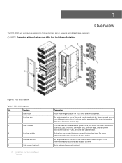
...Bar strip located on bottom of delivery may differ from the following illustrations. For more information about bus bars, see Bus bar middle. DSS 9000 system Table 1. The rear cabinet houses twelve system fans, one block controller distribution board (BCDB), one block controller (BC), one fan...bars, see Bus bar bottom. Bridge bus bar located between top and bottom bus bars. Rack cabinet filler panel (optional). 1 Overview The DSS 9000 rack enclosure is designed to hold and protect server, network, and data storage equipment. Feature 1 Bare rack 2 Bus bar top 3 ...
...Bar strip located on bottom of delivery may differ from the following illustrations. For more information about bus bars, see Bus bar middle. DSS 9000 system Table 1. The rear cabinet houses twelve system fans, one block controller distribution board (BCDB), one block controller (BC), one fan...bars, see Bus bar bottom. Bridge bus bar located between top and bottom bus bars. Rack cabinet filler panel (optional). 1 Overview The DSS 9000 rack enclosure is designed to hold and protect server, network, and data storage equipment. Feature 1 Bare rack 2 Bus bar top 3 ...
EMC Installation and Service Manual
Page 8
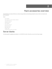
2 Rack accessories overview The DSS 9000 rack enclosure offers server and power supply blanks as well as shipping brackets, bus bar protectors and optional side panel accessories. Topics: • Server blanks &#...; Rack blank fillers • IM blank fillers • Locating Service Tag of your system Server blanks The following lists the available server blanks for the DSS 9000: full width, half width, and one third width blank chassis. 8 Installation and Service Manual Rack accessories overview
2 Rack accessories overview The DSS 9000 rack enclosure offers server and power supply blanks as well as shipping brackets, bus bar protectors and optional side panel accessories. Topics: • Server blanks &#...; Rack blank fillers • IM blank fillers • Locating Service Tag of your system Server blanks The following lists the available server blanks for the DSS 9000: full width, half width, and one third width blank chassis. 8 Installation and Service Manual Rack accessories overview

EMC Installation and Service Manual
Page 43
... connector. Table 13. Installation and Service Manual 43 Power bay overview Power bay features No. Item 1 Top cover 2 Bus Bar PB 3 PBPM 4 Rear IO module 5 DSS 9000 rack manager module 6 Power supply unit (PSU) 7 Management controller module Topics: • Power bay specifications • Power bay unit Description Top cover for the PSU...
... connector. Table 13. Installation and Service Manual 43 Power bay overview Power bay features No. Item 1 Top cover 2 Bus Bar PB 3 PBPM 4 Rear IO module 5 DSS 9000 rack manager module 6 Power supply unit (PSU) 7 Management controller module Topics: • Power bay specifications • Power bay unit Description Top cover for the PSU...
EMC Installation and Service Manual
Page 45
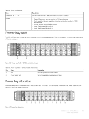
... specifications. • On/Off capacity through PMBus control • Up to 10 kW (single PB with 5+5) • Up to 18 kW (single PB with 9+1) The DSS 9000 leverages a power bay which houses up to ten AC power supply units (PSUs) to effectively sustain operations. Figure 26. Table 14. Power bay 1 MC + 10...
... specifications. • On/Off capacity through PMBus control • Up to 10 kW (single PB with 5+5) • Up to 18 kW (single PB with 9+1) The DSS 9000 leverages a power bay which houses up to ten AC power supply units (PSUs) to effectively sustain operations. Figure 26. Table 14. Power bay 1 MC + 10...

EMC Installation and Service Manual
Page 56
DSS 9000 rack manager module Table 25. DSS 9000 rack manager module features Item Board length Description 323.25 mm (12.73 inch) Board width 242.3 mm (9.54 inch) Net Weight 1,050 g (37.03 ounce) Connector • 2 x 8-port RJ45 • 1 x 2-port RJ45 • 1 x (2x2) Power connector • 1 x USB • 1 x (1x5) connector • 1 x Micro USB Switch Operating voltage/current 1 x Reset Button 12 V, current 2 A Infrastructure module LED definition 56 Installation and Service Manual Power bay overview DSS 9000 rack manager module Figure 33.
DSS 9000 rack manager module Table 25. DSS 9000 rack manager module features Item Board length Description 323.25 mm (12.73 inch) Board width 242.3 mm (9.54 inch) Net Weight 1,050 g (37.03 ounce) Connector • 2 x 8-port RJ45 • 1 x 2-port RJ45 • 1 x (2x2) Power connector • 1 x USB • 1 x (1x5) connector • 1 x Micro USB Switch Operating voltage/current 1 x Reset Button 12 V, current 2 A Infrastructure module LED definition 56 Installation and Service Manual Power bay overview DSS 9000 rack manager module Figure 33.

EMC Installation and Service Manual
Page 58
5 The DSS 9000 rack enclosure includes bus bar to the middle bus bars for upward distribution of the rack includes two bus bars, positive and negative. Bus bar top-P (positive, red) 58 Installation and Service Manual Bus bar overview The bus bars are coupled to the following areas: • Rack level • Block level • Power bay level Topics: • Rack level bus bar • Block level bus bar • Power bay level bus bars Rack level bus bar Bus bar overview Bus bar top The top of the system's power. Figure 35.
5 The DSS 9000 rack enclosure includes bus bar to the middle bus bars for upward distribution of the rack includes two bus bars, positive and negative. Bus bar top-P (positive, red) 58 Installation and Service Manual Bus bar overview The bus bars are coupled to the following areas: • Rack level • Block level • Power bay level Topics: • Rack level bus bar • Block level bus bar • Power bay level bus bars Rack level bus bar Bus bar overview Bus bar top The top of the system's power. Figure 35.
EMC Installation and Service Manual
Page 71
... damaged by discharges of static electricity. System components and electronic circuit boards can be extremely dangerous. Recommended tools • Phillips screwdriver #2 Service parts list • DSS 9000 System • Fan module • Power Installation and Service Manual 71 Installing and removing system components Read and follow these guidelines: • Wear a grounded wrist...
... damaged by discharges of static electricity. System components and electronic circuit boards can be extremely dangerous. Recommended tools • Phillips screwdriver #2 Service parts list • DSS 9000 System • Fan module • Power Installation and Service Manual 71 Installing and removing system components Read and follow these guidelines: • Wear a grounded wrist...

EMC Installation and Service Manual
Page 72
PSU blank - Half width server blank - DSS 9000 rack manager module - Infrastructure module - BC Servers Removing one third-width server Prerequisite 1 Ensure that you read the Safety instructions. Steps 1 Press the release latches on the side of the server. 2 Slide the server out of the block. 72 Installation and Service Manual Installing and removing system components Rear I/O - MC - PSU - Third width server blank - Full width server blank • PCBA module - - PBPM • Mechanical - MC cover -
PSU blank - Half width server blank - DSS 9000 rack manager module - Infrastructure module - BC Servers Removing one third-width server Prerequisite 1 Ensure that you read the Safety instructions. Steps 1 Press the release latches on the side of the server. 2 Slide the server out of the block. 72 Installation and Service Manual Installing and removing system components Rear I/O - MC - PSU - Third width server blank - Full width server blank • PCBA module - - PBPM • Mechanical - MC cover -

EMC Installation and Service Manual
Page 129
Steps 1 Loosen the captive screws securing the rack manager module to the power bay. 2 Grasp the rack manager module and slide it out of the power bay. Installation and Service Manual 129 Installing and removing system components Rack manager board (RMB) and infrastructure module (IM) Removing DSS 9000 rack manager module Prerequisite 1 Ensure that you read the Safety instructions.
Steps 1 Loosen the captive screws securing the rack manager module to the power bay. 2 Grasp the rack manager module and slide it out of the power bay. Installation and Service Manual 129 Installing and removing system components Rack manager board (RMB) and infrastructure module (IM) Removing DSS 9000 rack manager module Prerequisite 1 Ensure that you read the Safety instructions.

EMC Installation and Service Manual
Page 131
Installation and Service Manual 131 Installing and removing system components Installing DSS 9000 rack manager module 1 Align the rack manager module with the power bay. 2 Slide the rack manager module into the bay until it is flush in the power bay. 3 Turn the captive screws to secure the rack manager module to the power bay.
Installation and Service Manual 131 Installing and removing system components Installing DSS 9000 rack manager module 1 Align the rack manager module with the power bay. 2 Slide the rack manager module into the bay until it is flush in the power bay. 3 Turn the captive screws to secure the rack manager module to the power bay.

EMC Installation and Service Manual
Page 133
Steps 1 Remove the screws securing the IM to the bracket. 2 Hold the IM by the sides and lift it out to separate from the power bay, see Removing DSS 9000 rack manager module. Installation and Service Manual 133 Installing and removing system components Removing IM Prerequisites 1 Ensure that you read the Safety instructions. 2 Remove the rack manager module from the bracket.
Steps 1 Remove the screws securing the IM to the bracket. 2 Hold the IM by the sides and lift it out to separate from the power bay, see Removing DSS 9000 rack manager module. Installation and Service Manual 133 Installing and removing system components Removing IM Prerequisites 1 Ensure that you read the Safety instructions. 2 Remove the rack manager module from the bracket.

EMC DSS 9000 RackManager User Guide
Page 5
... in the DSS9000 rack using the internal rack ManagementNetwork. 2 Overview The Rack Level Management is the unique feature of DSS 9000, which is an embedded CentOS server in the DSS9000 rack that interconnects RackManager directly with the sled BMCs and other ...External RJ45 Ethernet Interface • DSS9000 integrated with node BMCs. Overview 5 over the high-speed GbE internal management network. The DSS 9000 RackManager is designed to meet the expectations of modern scalable platform hardware. It has an enhanced GbE internal ManagementNetwork that provides enhanced...
... in the DSS9000 rack using the internal rack ManagementNetwork. 2 Overview The Rack Level Management is the unique feature of DSS 9000, which is an embedded CentOS server in the DSS9000 rack that interconnects RackManager directly with the sled BMCs and other ...External RJ45 Ethernet Interface • DSS9000 integrated with node BMCs. Overview 5 over the high-speed GbE internal management network. The DSS 9000 RackManager is designed to meet the expectations of modern scalable platform hardware. It has an enhanced GbE internal ManagementNetwork that provides enhanced...

EMC DSS 9000 RackManager User Guide
Page 6
3 Connecting to the RackManager 1 Physical Network Connection a Plug in a RJ45 cable which is connected to your DHCP server pool from which is located on the DSS 9000's IM module. b This will assign an IP Address from XXX.XXX.XXX [root@RackManagerMini1 ~]# 6 Connecting to the port labeled "Mgmt1" which you can access the ...
3 Connecting to the RackManager 1 Physical Network Connection a Plug in a RJ45 cable which is connected to your DHCP server pool from which is located on the DSS 9000's IM module. b This will assign an IP Address from XXX.XXX.XXX [root@RackManagerMini1 ~]# 6 Connecting to the port labeled "Mgmt1" which you can access the ...