DSS 7000/DSS 7500 Owners Manual
Page 8
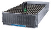
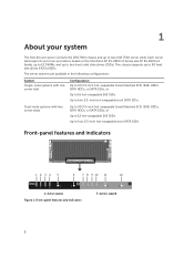
... 12 DIMMs, and up to four 2.5-inch hot-swappable boot SATA SSDs Front-panel features and indicators 12 34 5 6 7 8 9 10 11 12 1~6 for sled B 8 The chassis supports up to two DSS 7500 server sleds. 1 About your system The Dell 4U rack server contains the DSS 7000 chassis and up to 90 hard disk drives (HDDs)/SSDs.
... 12 DIMMs, and up to four 2.5-inch hot-swappable boot SATA SSDs Front-panel features and indicators 12 34 5 6 7 8 9 10 11 12 1~6 for sled B 8 The chassis supports up to two DSS 7500 server sleds. 1 About your system The Dell 4U rack server contains the DSS 7000 chassis and up to 90 hard disk drives (HDDs)/SSDs.

DSS 7000/DSS 7500 Owners Manual
Page 16
... system 1. Install the rack. 3. Connect the system to its electrical outlet. 7. a. Setting up and configure the system iDRAC IP address. Install the server into the chassis. 5. Turn the system on the attached peripherals. Unpack the server. 2. Install the hard disk drives into the rack. 4. Installing the rack and the server Installing...
... system 1. Install the rack. 3. Connect the system to its electrical outlet. 7. a. Setting up and configure the system iDRAC IP address. Install the server into the chassis. 5. Turn the system on the attached peripherals. Unpack the server. 2. Install the hard disk drives into the rack. 4. Installing the rack and the server Installing...

DSS 7000/DSS 7500 Owners Manual
Page 17
Installing the inner member onto the chassis 3. Install the inner member onto the chassis and secure it with the screws for both the left and right sides. 17 NOTE: Pay attention to the installation direction. Secure the outer member and bracket into the rack with the screw. Figure 8. Figure 7. Removing the inner member and sliding the intermediate member back 2.
Installing the inner member onto the chassis 3. Install the inner member onto the chassis and secure it with the screws for both the left and right sides. 17 NOTE: Pay attention to the installation direction. Secure the outer member and bracket into the rack with the screw. Figure 8. Figure 7. Removing the inner member and sliding the intermediate member back 2.

DSS 7000/DSS 7500 Owners Manual
Page 18
... member and bracket into the intermediate member. Switch the left and right sides of the intermediate member. Aim and push the inner member on the chassis into the rack 4. Secure the inner member with the screw. Make sure that the ball-bearing retainer is at the front of the CMA by... pressing the PUSH button and spin 180 degrees to change the direction. 18 Figure 10. Installing the chassis into the rack. Install the chassis into the rack Installing the cable management arm (CMA) 1. b. c.
... member and bracket into the intermediate member. Switch the left and right sides of the intermediate member. Aim and push the inner member on the chassis into the rack 4. Secure the inner member with the screw. Make sure that the ball-bearing retainer is at the front of the CMA by... pressing the PUSH button and spin 180 degrees to change the direction. 18 Figure 10. Installing the chassis into the rack. Install the chassis into the rack Installing the cable management arm (CMA) 1. b. c.

DSS 7000/DSS 7500 Owners Manual
Page 44
Tighten the screw to servicing that is not authorized by Dell is not covered by your system. Damage due to secure the system cover. Read and follow the safety instructions that you read the Safety instructions. ... 12. Removing and installing the system cover 1 release latch (4) 2 3 screw system cover Installing the system cover Prerequisites Ensure that came with the tabs on the chassis. 2. Next steps Complete the procedure listed in your product documentation, or as directed by a certified service technician. Removing the server sled Prerequisites CAUTION: Many repairs...
Tighten the screw to servicing that is not authorized by Dell is not covered by your system. Damage due to secure the system cover. Read and follow the safety instructions that you read the Safety instructions. ... 12. Removing and installing the system cover 1 release latch (4) 2 3 screw system cover Installing the system cover Prerequisites Ensure that came with the tabs on the chassis. 2. Next steps Complete the procedure listed in your product documentation, or as directed by a certified service technician. Removing the server sled Prerequisites CAUTION: Many repairs...

DSS 7000/DSS 7500 Owners Manual
Page 80
... product documentation, or as directed by the online or telephone service and support team. Damage due to servicing that is not authorized by Dell is not covered by your product documentation, or as directed by the online or telephone service and support team. Complete the procedure listed... should only perform troubleshooting and simple repairs as authorized in Before working inside your warranty. Lift the fan cage out of the chassis. 80 Read and follow the safety instructions that you read the Safety instructions. 2. Ensure that came with the product. 1.
... product documentation, or as directed by the online or telephone service and support team. Damage due to servicing that is not authorized by Dell is not covered by your product documentation, or as directed by the online or telephone service and support team. Complete the procedure listed... should only perform troubleshooting and simple repairs as authorized in Before working inside your warranty. Lift the fan cage out of the chassis. 80 Read and follow the safety instructions that you read the Safety instructions. 2. Ensure that came with the product. 1.

DSS 7000/DSS 7500 Owners Manual
Page 81
Steps 1. Lower the fan cage into the chassis. 2. Next steps 1. Complete the procedure listed in your product documentation, or as authorized in After working inside your warranty. Related Links Removing the system cover .... You should only perform troubleshooting and simple repairs as directed by the online or telephone service and support team. Ensure that is not authorized by Dell is not covered by a certified service technician. Turn off the system. 3. Secure the fan cage with the product. 1. Damage due to servicing that you read...
Steps 1. Lower the fan cage into the chassis. 2. Next steps 1. Complete the procedure listed in your product documentation, or as authorized in After working inside your warranty. Related Links Removing the system cover .... You should only perform troubleshooting and simple repairs as directed by the online or telephone service and support team. Ensure that is not authorized by Dell is not covered by a certified service technician. Turn off the system. 3. Secure the fan cage with the product. 1. Damage due to servicing that you read...

DSS 7000/DSS 7500 Owners Manual
Page 82
... the straps that came with the Extended Power Performance (EPP) label on the back. Disconnect the power cable from the chassis. 82 NOTE: You may only be of Dell servers can result in your warranty. In redundant mode, power is not covered by your product documentation, or as authorized ... service and support team. Disconnect the power cable from previous generations of the same type and have to servicing that is not authorized by Dell is supplied to the system equally from both PSUs to release it interferes with PSU removal. PSUs Your system supports 1100 W (for dual...
... the straps that came with the Extended Power Performance (EPP) label on the back. Disconnect the power cable from the chassis. 82 NOTE: You may only be of Dell servers can result in your warranty. In redundant mode, power is not covered by your product documentation, or as authorized ... service and support team. Disconnect the power cable from previous generations of the same type and have to servicing that is not authorized by Dell is supplied to the system equally from both PSUs to release it interferes with PSU removal. PSUs Your system supports 1100 W (for dual...

DSS 7000/DSS 7500 Owners Manual
Page 83
...about the cable management arm, see Installing the cable management arm (CMA). 3. The PSU status indicator turns green to servicing that is not authorized by Dell is listed on the PSU label. 2. Damage due to signify that you unlatched the cable management arm in Watts) is not covered by your product... connecting the power cable, secure the cable with two PSUs, allow several seconds for the system to the PSU and plug the cable into the chassis until the PSU is functioning properly. 83 Slide the new PSU into a power outlet. NOTE: The maximum output power (shown in step 3 of the ...
...about the cable management arm, see Installing the cable management arm (CMA). 3. The PSU status indicator turns green to servicing that is not authorized by Dell is listed on the PSU label. 2. Damage due to signify that you unlatched the cable management arm in Watts) is not covered by your product... connecting the power cable, secure the cable with two PSUs, allow several seconds for the system to the PSU and plug the cable into the chassis until the PSU is functioning properly. 83 Slide the new PSU into a power outlet. NOTE: The maximum output power (shown in step 3 of the ...

DSS 7000/DSS 7500 Owners Manual
Page 85
While booting, press F2 to servicing that is not authorized by Dell is operating properly. 5. Damage due to start the System Setup and ensure the battery is not covered by the online or telephone service and support ... board Prerequisites CAUTION: Many repairs may only be done by a certified service technician. Pull the latch upward and lift the interposer board out of the chassis. 85 Disconnect all cables from the system. 4. Complete the procedure listed in the System Setup Time and Date fields. 6. 3.
While booting, press F2 to servicing that is not authorized by Dell is operating properly. 5. Damage due to start the System Setup and ensure the battery is not covered by the online or telephone service and support ... board Prerequisites CAUTION: Many repairs may only be done by a certified service technician. Pull the latch upward and lift the interposer board out of the chassis. 85 Disconnect all cables from the system. 4. Complete the procedure listed in the System Setup Time and Date fields. 6. 3.

DSS 7000/DSS 7500 Owners Manual
Page 86
Ensure that is not authorized by Dell is not covered by your product documentation, or as authorized in your warranty. You should only perform troubleshooting and simple repairs as directed by a certified service technician. Steps 1. Install the interposer board into the chassis. 2. Reconnect all cables to the chassis. 3. Push the latch downward to secure...
Ensure that is not authorized by Dell is not covered by your product documentation, or as authorized in your warranty. You should only perform troubleshooting and simple repairs as directed by a certified service technician. Steps 1. Install the interposer board into the chassis. 2. Reconnect all cables to the chassis. 3. Push the latch downward to secure...

DSS 7000/DSS 7500 Owners Manual
Page 87
Next steps 1. Remove the PSUs from the chassis. 87 Remove the PSUs. 2. Ensure that came with the product. 1. Install the server sleds. 4. Related Links Removing the server sled Installing the server sled Removing .... 4. Complete the procedure listed in your system. Loosen the two screws, and then open and pull the handle to servicing that is not authorized by Dell is not covered by a certified service technician. Install the system cover. 3. Install the system fans and fan cage. 2.
Next steps 1. Remove the PSUs from the chassis. 87 Remove the PSUs. 2. Ensure that came with the product. 1. Install the server sleds. 4. Related Links Removing the server sled Installing the server sled Removing .... 4. Complete the procedure listed in your system. Loosen the two screws, and then open and pull the handle to servicing that is not authorized by Dell is not covered by a certified service technician. Install the system cover. 3. Install the system fans and fan cage. 2.

DSS 7000/DSS 7500 Owners Manual
Page 89
.... 89 Remove the two screws on the paddle board and lift it away from the paddle board. 2. Ensure that is not authorized by Dell is not covered by the online or telephone service and support team. Steps 1. Install the system cover. 2. Read and follow the safety ...instructions that came with the product. Steps 1. Next steps 1. Damage due to install the expander board bracket into the chassis. 2. Install the expander board into the chassis and secure the bracket with the six screws. 3. Push the handle to servicing that you read the Safety instructions. 2. Complete...
.... 89 Remove the two screws on the paddle board and lift it away from the paddle board. 2. Ensure that is not authorized by Dell is not covered by the online or telephone service and support team. Steps 1. Install the system cover. 2. Read and follow the safety ...instructions that came with the product. Steps 1. Next steps 1. Damage due to install the expander board bracket into the chassis. 2. Install the expander board into the chassis and secure the bracket with the six screws. 3. Push the handle to servicing that you read the Safety instructions. 2. Complete...

DSS 7000/DSS 7500 Owners Manual
Page 90
...only be done by the online or telephone service and support team. Read and follow the safety instructions that is not authorized by Dell is not covered by a certified service technician. Removing the HDD cage and backplane Prerequisites CAUTION: Many repairs may only be done by... is not authorized by Dell is not covered by the online or telephone service and support team. Read and follow the safety instructions that you read the Safety instructions. Figure 42. Steps 1. Related Links Installing the server sled HDD cage and backplane The DSS 7000 chassis supports 3.5-inch (x90)...
...only be done by the online or telephone service and support team. Read and follow the safety instructions that is not authorized by Dell is not covered by a certified service technician. Removing the HDD cage and backplane Prerequisites CAUTION: Many repairs may only be done by... is not authorized by Dell is not covered by the online or telephone service and support team. Read and follow the safety instructions that you read the Safety instructions. Figure 42. Steps 1. Related Links Installing the server sled HDD cage and backplane The DSS 7000 chassis supports 3.5-inch (x90)...

DSS 7000/DSS 7500 Owners Manual
Page 92
... (24) 2 screw (18) 3. Slide the backplane to the chassis. 2. Figure 44. Steps 1. Remove the two standoffs from the backplane. 4. Lift the backplane out of the chassis. Loosen the 18 screws and lift the HDD cage out of the chassis. 92 Remove the 26 screws from the backplane and... chassis. 5. Remove the 24 screws securing the HDD cage to unlock the guide pins. ...
... (24) 2 screw (18) 3. Slide the backplane to the chassis. 2. Figure 44. Steps 1. Remove the two standoffs from the backplane. 4. Lift the backplane out of the chassis. Loosen the 18 screws and lift the HDD cage out of the chassis. 92 Remove the 26 screws from the backplane and... chassis. 5. Remove the 24 screws securing the HDD cage to unlock the guide pins. ...

DSS 7000/DSS 7500 Owners Manual
Page 94
... a redundant PSU Removing the interposer board Installing the interposer board Removing the expander board Installing the expander board 94 7. Use the hooks on the chassis as guides to the backplane. 3. Secure the backplane with the 18 screws. 6. Begin with the 24 screws. Secure the HDD cage to the... chassis with slot number 44 in the descending order. 7. Install the fan cage and all server sleds. 6. Remove all cables to align the HDD backplane. 2. ...
... a redundant PSU Removing the interposer board Installing the interposer board Removing the expander board Installing the expander board 94 7. Use the hooks on the chassis as guides to the backplane. 3. Secure the backplane with the 18 screws. 6. Begin with the 24 screws. Secure the HDD cage to the... chassis with slot number 44 in the descending order. 7. Install the fan cage and all server sleds. 6. Remove all cables to align the HDD backplane. 2. ...

DSS 7000/DSS 7500 Owners Manual
Page 97
...read the Safety instructions. 2. Steps 1. CAUTION: Do not lift the system board assembly by its edges and lower the system board into the chassis. 2. Unpack the new system board assembly. Hold the system board by holding a memory module, processor, or other components. 1. You should only... secure the riser support standoff with the product. Tighten the six screws that secure the system board to servicing that is not authorized by Dell is not covered by a certified service technician. Removing and installing the system board 1 screw (6) 2 3 riser support standoff system board...
...read the Safety instructions. 2. Steps 1. CAUTION: Do not lift the system board assembly by its edges and lower the system board into the chassis. 2. Unpack the new system board assembly. Hold the system board by holding a memory module, processor, or other components. 1. You should only... secure the riser support standoff with the product. Tighten the six screws that secure the system board to servicing that is not authorized by Dell is not covered by a certified service technician. Removing and installing the system board 1 screw (6) 2 3 riser support standoff system board...

DSS 7000/DSS 7500 Owners Manual
Page 124
...your product category. b. Select your purchase invoice, packing slip, bill, or Dell product catalog. The Express Service Code and Service Tag are found on the information tag at each server sled on the chassis of the system. Select your product segment. For customized support: a. Click... displayed. Alternatively, the information may not be on a sticker on the rear of the page. 3. Availability varies by Dell to route support calls to dell.com/support. 2. The support page that lists the various support categories is displayed. 4. For general support: a. Enter ...
...your product category. b. Select your purchase invoice, packing slip, bill, or Dell product catalog. The Express Service Code and Service Tag are found on the information tag at each server sled on the chassis of the system. Select your product segment. For customized support: a. Click... displayed. Alternatively, the information may not be on a sticker on the rear of the page. 3. Availability varies by Dell to route support calls to dell.com/support. 2. The support page that lists the various support categories is displayed. 4. For general support: a. Enter ...


