
Service Manual
Page 1
SCC-L04K-A Picture tube Phosphor Type Transmission Ratio Faceplate Viewable image size Resolution Horizontal Vertical Display picture size Input signal Video Sync N3 CHASSIS SPECIFICATIONS 0.25 - 0.27 mm aperture grill pitch, 21 inches measured diagonally, 90 degree deflection P22 Approx. 39% Anti Reflective (AR)/Anti Static (AS) coating Approx... to 80% (Non-condensing) Non-operating 5% to 90% (Non-condensing) Design and specifications are subject to change without notice. SERVICE MANUAL D1626HT US Model Canadian Model AEP Model EQ Model SH Model J Model Chassis No. COLOR MONITOR R
SCC-L04K-A Picture tube Phosphor Type Transmission Ratio Faceplate Viewable image size Resolution Horizontal Vertical Display picture size Input signal Video Sync N3 CHASSIS SPECIFICATIONS 0.25 - 0.27 mm aperture grill pitch, 21 inches measured diagonally, 90 degree deflection P22 Approx. 39% Anti Reflective (AR)/Anti Static (AS) coating Approx... to 80% (Non-condensing) Non-operating 5% to 90% (Non-condensing) Design and specifications are subject to change without notice. SERVICE MANUAL D1626HT US Model Canadian Model AEP Model EQ Model SH Model J Model Chassis No. COLOR MONITOR R

Service Manual
Page 2
... WHICH THE DEGAUSS COIL HAS BEEN REMOVED. NE LES REMPLACER QUE PAR UNE PIÈCE PORTANT LE NUMÉRO SPECIFIÉ. D1626HT SAFETY CHECK-OUT (US Model only) After correcting the original service problem, perform the following safety checks before releasing the set to the customer and recommend their replacement...
... WHICH THE DEGAUSS COIL HAS BEEN REMOVED. NE LES REMPLACER QUE PAR UNE PIÈCE PORTANT LE NUMÉRO SPECIFIÉ. D1626HT SAFETY CHECK-OUT (US Model only) After correcting the original service problem, perform the following safety checks before releasing the set to the customer and recommend their replacement...

Service Manual
Page 19
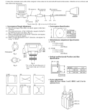
..." 128 ± 40 After adjustment, save the service data. 9. Note: Off the outputs from the non- Return to the original value after use.) Demagnetize the CRT surface with respect to the green. 0 ± 3 0 ± 5 0 ± 3 ± 6 ± 6 ± 6 (µm) 0 ± 7.5 0 ± 3 0±5 0±5 0 ± 7.5 0 ± 3 (&#... magnetism sensor reading VX and VY to the designated part of four corners using an earth magnetism sensor and a LCC coil. This model has an automatic earth magnetism correction function by moving "LCC NS", "LCC LT", "LCC LB", "LCC RT" and "LCC ...
..." 128 ± 40 After adjustment, save the service data. 9. Note: Off the outputs from the non- Return to the original value after use.) Demagnetize the CRT surface with respect to the green. 0 ± 3 0 ± 5 0 ± 3 ± 6 ± 6 ± 6 (µm) 0 ± 7.5 0 ± 3 0±5 0±5 0 ± 7.5 0 ± 3 (&#... magnetism sensor reading VX and VY to the designated part of four corners using an earth magnetism sensor and a LCC coil. This model has an automatic earth magnetism correction function by moving "LCC NS", "LCC LT", "LCC LB", "LCC RT" and "LCC ...
Service Manual
Page 20
... so that the protruding parts of the 2 magnet rings agree with each other . • Convergence Specification B For SH Model V MODE 1-5 A A 0.28 mm B 0.32 mm • White Balance Adjustment Specification (1) 9300K x = 0.281... TILT (TLH) RB BR YBH FBT R B R B HDK1 (V) HDK2 (H) IBM AT Computer as a Jig 1 1-690-391-21 2 A-1500-819-A Interface Unit 3 3-702-691-01 Connector Attachment To BUS CONNECTOR D-sub (9 Pin [female]) mini Din (8Pin)... (2) Place the protrusions of the 6-fold poles magnet attached to the CRT neck upon each other . (Fig. 1) (3) Make rough adjustment of...
... so that the protruding parts of the 2 magnet rings agree with each other . • Convergence Specification B For SH Model V MODE 1-5 A A 0.28 mm B 0.32 mm • White Balance Adjustment Specification (1) 9300K x = 0.281... TILT (TLH) RB BR YBH FBT R B R B HDK1 (V) HDK2 (H) IBM AT Computer as a Jig 1 1-690-391-21 2 A-1500-819-A Interface Unit 3 3-702-691-01 Connector Attachment To BUS CONNECTOR D-sub (9 Pin [female]) mini Din (8Pin)... (2) Place the protrusions of the 6-fold poles magnet attached to the CRT neck upon each other . (Fig. 1) (3) Make rough adjustment of...

Service Manual
Page 32
... ¡ 8-738-791-81 ITC ASSY (21SRG-R1) 52-54, 72 52 ¡ 8-738-791-05 PICTURE TUBE (21SRG) [except SH model] 52 ¡ 8-738-792-05 PICTURE TUBE (21SRG) [SH model] 53 ¡ 8-451-493-11 DEFLECTIN YOKE (Y21SRL-M) 54 4-050-492-01 SPACER, DY 55 * 4-047-316-01 SPRING, TENSION...
... ¡ 8-738-791-81 ITC ASSY (21SRG-R1) 52-54, 72 52 ¡ 8-738-791-05 PICTURE TUBE (21SRG) [except SH model] 52 ¡ 8-738-792-05 PICTURE TUBE (21SRG) [SH model] 53 ¡ 8-451-493-11 DEFLECTIN YOKE (Y21SRL-M) 54 4-050-492-01 SPACER, DY 55 * 4-047-316-01 SPRING, TENSION...

Service Manual
Page 48
...FILTER, CLAMP (FERRITE CORE) * 1-694-313-12 TERMINAL BOARD ASSY, I/O ¡ 1-769-752-11 CORD SET, POWER (7A/125V) [J model] ¡ 1-776-027-51 CORD SET, POWER (10A/125V) [U/C model] 1-777-743-11 CABLE ASSY (15P D SUB ×2 CONNECTOR) ¡ 8-451-493-11 DEFLECTION YOKE (Y21SRL-M) V901 ¡ 8-738... 15K 5% 1/4W F 5% 1/4W F 5% 2W F R5417 1-216-308-00 RES, CHIP 4.7 R5419 1-216-089-91 RES, CHIP 47K - 69 - L REF.NO. PART NO. D1626HT The components identified by shading and mark ¡ are critical for safety. Les composants identifiés per un tramé et une marque ¡ sont...
...FILTER, CLAMP (FERRITE CORE) * 1-694-313-12 TERMINAL BOARD ASSY, I/O ¡ 1-769-752-11 CORD SET, POWER (7A/125V) [J model] ¡ 1-776-027-51 CORD SET, POWER (10A/125V) [U/C model] 1-777-743-11 CABLE ASSY (15P D SUB ×2 CONNECTOR) ¡ 8-451-493-11 DEFLECTION YOKE (Y21SRL-M) V901 ¡ 8-738... 15K 5% 1/4W F 5% 1/4W F 5% 2W F R5417 1-216-308-00 RES, CHIP 4.7 R5419 1-216-089-91 RES, CHIP 47K - 69 - L REF.NO. PART NO. D1626HT The components identified by shading and mark ¡ are critical for safety. Les composants identifiés per un tramé et une marque ¡ sont...


