Dell D1626HT - UltraScan 1600HS - 21" CRT Display Support and Manuals
Get Help and Manuals for this Dell item
View All Support Options Below
Free Dell D1626HT manuals!
Problems with Dell D1626HT?
Ask a Question
Free Dell D1626HT manuals!
Problems with Dell D1626HT?
Ask a Question
Dell D1626HT Videos

Faulty Dell D1626HT Trinitron monitor
Duration: :35
Total Views: 612
Duration: :35
Total Views: 612
Popular Dell D1626HT Manual Pages
Service Manual - Page 1

COLOR MONITOR
R
SERVICE MANUAL
D1626HT
US Model Canadian Model
AEP Model EQ Model SH Model J Model
Chassis No. SCC-L04K-A
Picture tube
Phosphor Type Transmission Ratio Faceplate Viewable image size Resolution Horizontal Vertical Display picture size
Input signal Video Sync
N3 CHASSIS
SPECIFICATIONS
0.25 - 0.27 mm aperture grill pitch, 21 inches measured diagonally, 90 degree deflection ...
Service Manual - Page 2

... the line cords for this job.
3. Check that were installed during a previous repair.
A)
WARNING!! NE JAMAIS METTRE SOUS TENSION QUAND LA BOBINE DE DEMAGNETISATION EST ENLEVÉE. D1626HT
SAFETY CHECK-OUT (US Model only)
After correcting the original service problem, perform the following safety checks before releasing the set to the home position. Check the B+ and HV...
Service Manual - Page 4

... 5-4. DISASSEMBLY 2-1. Picture Tube Removal 17
3. Block Diagrams 21 5-2. Packing Materials 53
7. A Board Removal 14 2-5. Service Position 16 2-8. Schematic Diagrams and Printed Wiring Boards ..... 29 (1) Schematic Diagram of D Board 33 (2) Schematic Diagrams of G, GA, H, J and L Boards 37 (3) Schematic Diagram of A Board 44 5-5. Picture Tube 52 6-3. TABLE...
Service Manual - Page 5

... of the Tilt/Swivel
With the tilt/swivel, you can adjust this monitor to the factory settings.
2 (AUTO SIZING AND CENTERING) button (page 6) Automatically adjusts the...video signals and SYNC signals
C s
9 Video input 2 connector (5 BNC) Inputs RGB video signals (0.7 Vp-p, positive) and SYNC C t signals. Signal
1
Red
Pin No. Parts and Controls
Front
Rear
1
(RESET) button (pages 7 and 11)...
Service Manual - Page 6

...is intended for a few seconds while performing the Sizing and Centering function. If this happens, manually select the computer signal you want to view as an MS-DOS prompt). • The screen...the power of 5:4 (resolution: 1280 × 1024) does not fill the screen to select
"1" or "2." Input Signal Selection
This monitor has two signal input terminals (HD15 and 5 BNC) and can easily adjust ...
Service Manual - Page 7

...
ZZ...
1 MIN
UNLOCK
MANUAL DEGAUSS
EN F ES D J C s C t PL To adjust the monitor settings: 1 Press the MENU button to display the MENU OSD. 2 Highlight the desired OSD using the BRIGHTNESS and
CONTRAST buttons and press the MENU button again. 3 If necessary, use the BRIGHTNESS buttons to select a
specific item. 4 Adjust the monitor setting using the BRIGHTNESS and...
Service Manual - Page 9

... buttons to select the
desired adjustment item. 4 Press the > (CONTRAST) ? // buttons to activate the
manual degauss, select the input signal, move the OSD position, change the OSD position, press the
ES
¨...try to normal viewing.
If you select "OFF," the
C s
monitor does not go into Power Saving mode.
This setting is needed, allow a minimum
interval of 20 minutes for the current...
Service Manual - Page 11

... settings. TechnicaGl eFtetiantgureSstarted
Specifications
Picture tube
0.25 - 0.27 mm aperture grill pitch, 21 inches measured diagonally, 90 degree deflection
Phosphor Type
P22
Transmission Ratio
Approx. 39%
Faceplate
Anti Reflective (AR)/Anti Static (AS) coating
Viewable image size
Approx. 403.8 × 302.2 mm (w/h) (16 × 12 in.) 19.8" viewing image
Resolution Horizontal...
Service Manual - Page 12
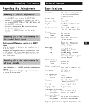
... reset to the factory settings. Resetting all of the adjustments for all of the adjustments for the current input signal
While there is no OSD displayed, press the
(RESET)
button. Customizing Your Monitor
Resetting the Adjustments
Resetting a specific adjustment:
1 Press the MENU button to display the MENU OSD
2 Highlight the OSD containing the...
Service Manual - Page 19

... respectively.
This model has an automatic earth magnetism correction
function by or power-off the power to the designated part of the CRT
neck.
5. After adjustment, set inside the fluorescent ... condi- Adjust the tilt of four corners using a hand degauss while monitor (LCC coil) is within the specification given right. 4 corner adjust target : within the following range.
When...
Service Manual - Page 20
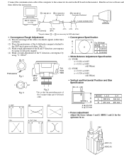
...service software and then follow the instruction. Protrusions Fig. 1
**
Fig. 3
XBV XCV APH
TLV YCH YBH
60°
Fig. 2 * Set so that the protruding parts of
the 2 magnet rings agree with each other .
• Convergence Specification
B For SH Model
V
MODE 1-5 A
A 0.28 mm
B 0.32 mm
• White Balance Adjustment Specification...D board on the monitor.
Connect the communication cable...
Service Manual - Page 23

...replacing the part in µF unless otherwise noted. (pF: µµF)
Capacitors without voltage indication are included.)
D G
S
D G
S
D S
G
Ver.1.4
p •
: panel designation, and adjustment for repair.
• All variable and adjustable resistors have one for each set... resistor.
• ¢ : internal component. FRAME SCHEMATIC DIAGRAM
CONNECTOR PANEL
54 321 10 9 8 7 6
...
Service Manual - Page 28

...87.0 474.0 6.5
A(VIDEO AMP,RGB OUT)
3.0 Vp-p (H)
• A BOARD VOLTAGE LIST
Ref. G_IN VBB GND VBB R_IN R_E.P. D1626HT
(3) Schematic Diagram of A Board
D1626HT D1626HT
CONNECTOR RANEL
TO D BOARD CN511
54321 10 9 8 7 6
15 14 13 12 11
HD15
VD HD B
GR 5BNC
• A ...16 15 14 13 12 11 10 9 8 7 6 5 4 3 2 1 19 20 21 22 23 24 25 26 27 28 29 30 31 32 33 34 35 36
26 25 24 23 22...
Service Manual - Page 33

...for routine
service. PART NO.
DESCRIPTION
The components identified by shading
and mark ¡ are seldom required for safety. When indicating parts by ...Replace only with part number specified. Should replacement be
• All variable and adjustable resistors have been carefully factory- • All resistors are critical for each set in ohms
selected for safety.
D1626HT...
Service Manual - Page 48

D1626HT
The components identified by shading
and mark ¡...CORE) * 1-694-313-12 TERMINAL BOARD ASSY, I/O ¡ 1-769-752-11 CORD SET, POWER (7A/125V) [J model] ¡ 1-776-027-51 CORD SET, POWER (10A/125V)
[U/C model] 1-777-743-11 CABLE ASSY
(15P D SUB ×2 CONNECTOR)
¡ 8-451-... ¡ sont critiques pour la
sécurité. Replace only with part number specified. PART NO. PART NO.
Dell D1626HT Reviews
We have not received any reviews for Dell yet.