
Service Manual
Page 1
SERVICE MANUAL D1626HT US Model Canadian Model AEP Model EQ Model SH Model J Model Chassis No. COLOR MONITOR R SCC-L04K-A Picture tube Phosphor Type Transmission Ratio Faceplate Viewable image size Resolution Horizontal Vertical Display picture size Input signal Video Sync N3 CHASSIS SPECIFICATIONS 0.25 - 0.27 mm aperture grill pitch, 21 inches measured diagonally, 90 degree...
SERVICE MANUAL D1626HT US Model Canadian Model AEP Model EQ Model SH Model J Model Chassis No. COLOR MONITOR R SCC-L04K-A Picture tube Phosphor Type Transmission Ratio Faceplate Viewable image size Resolution Horizontal Vertical Display picture size Input signal Video Sync N3 CHASSIS SPECIFICATIONS 0.25 - 0.27 mm aperture grill pitch, 21 inches measured diagonally, 90 degree...

Service Manual
Page 3
...-off (3rd mode) ≤ 5 W Approx. 10 sec. 5 Power-off mode and the u indicator lights up orange. Once the monitor detects horizontal and vertical sync signals, the monitor automatically resumes normal operation mode. H-FREQ H. ACTIV - V. SYNC - MODE 3 VESA 1280 X 1024 135.000 MHz 79.976 kHz usec... Green and orange alternate Green and orange alternate Orange Off Orange flashing DIAGNOSIS Note If no video signal is input to the monitor, the "NO INPUT SIGNAL" message appears (page 13). FP H. VERTICAL - BLK V. FP V. After about 60 seconds, the Power Saving...
...-off (3rd mode) ≤ 5 W Approx. 10 sec. 5 Power-off mode and the u indicator lights up orange. Once the monitor detects horizontal and vertical sync signals, the monitor automatically resumes normal operation mode. H-FREQ H. ACTIV - V. SYNC - MODE 3 VESA 1280 X 1024 135.000 MHz 79.976 kHz usec... Green and orange alternate Green and orange alternate Orange Off Orange flashing DIAGNOSIS Note If no video signal is input to the monitor, the "NO INPUT SIGNAL" message appears (page 13). FP H. VERTICAL - BLK V. FP V. After about 60 seconds, the Power Saving...

Service Manual
Page 5
...) ./> buttons (page 6) Adjust the picture brightness. Signal 8 Blue Ground 2 Green (Composite 9 DDC +5V* Sync on , and lights up orange when the monitor is on Green) 10 Ground 3 Blue 11 ID (ground) 4 ID (ground) 12 SDA (serial data) 5 DDC Ground* 13 Horizontal Sync 6 Red Ground ...14 Vertical Sync 7 Green Ground 15 SCL (serial clock) * Display Data Channel (DDC) standard of VESA. 5 Operate as the ./> buttons when adjusting other items. EN 6 u (POWER) switch and indicator (page 12) Turns...
...) ./> buttons (page 6) Adjust the picture brightness. Signal 8 Blue Ground 2 Green (Composite 9 DDC +5V* Sync on , and lights up orange when the monitor is on Green) 10 Ground 3 Blue 11 ID (ground) 4 ID (ground) 12 SDA (serial data) 5 DDC Ground* 13 Horizontal Sync 6 Red Ground ...14 Vertical Sync 7 Green Ground 15 SCL (serial clock) * Display Data Channel (DDC) standard of VESA. 5 Operate as the ./> buttons when adjusting other items. EN 6 u (POWER) switch and indicator (page 12) Turns...

Service Manual
Page 6
...8226; The screen may automatically switch to the edges, the picture is on, manually select the input signal you select "2" The monitor displays the signal from the computer connected to two computers. The picture fills the screen. OPTION ON ZZ... 1 MIN UNLOCK MANUAL DEGAUSS ... Press the MENU button to select "1" or "2." The BRIGHTNESS/CONTRAST OSD appears. This is because the monitor automatically switches from the other computer. When you select "1" The monitor displays the signal from the computer connected to select (INPUT). This is not a malfunction. • Although a...
...8226; The screen may automatically switch to the edges, the picture is on, manually select the input signal you select "2" The monitor displays the signal from the computer connected to two computers. The picture fills the screen. OPTION ON ZZ... 1 MIN UNLOCK MANUAL DEGAUSS ... Press the MENU button to select "1" or "2." The BRIGHTNESS/CONTRAST OSD appears. This is because the monitor automatically switches from the other computer. When you select "1" The monitor displays the signal from the computer connected to select (INPUT). This is not a malfunction. • Although a...

Service Manual
Page 7
... you finish adjusting the setting, press the MENU button to return to the MENU OSD. To adjust the monitor settings: 1 Press the MENU button to display the MENU OSD. 2 Highlight the desired OSD using the BRIGHTNESS and CONTRAST buttons and press the MENU button again. 3... can adjust most of these OSDs from the MENU OSD. To adjust monitor settings using the OSDs (On-screen Display). GeCttuinsgtomStizairntegdYour Monitor The OSD (On-screen Display) System Introducing the OSD System You can access any of the monitor's settings using the OSDs, follow the steps below: Basic controls: &#...
... you finish adjusting the setting, press the MENU button to return to the MENU OSD. To adjust the monitor settings: 1 Press the MENU button to display the MENU OSD. 2 Highlight the desired OSD using the BRIGHTNESS and CONTRAST buttons and press the MENU button again. 3... can adjust most of these OSDs from the MENU OSD. To adjust monitor settings using the OSDs (On-screen Display). GeCttuinsgtomStizairntegdYour Monitor The OSD (On-screen Display) System Introducing the OSD System You can access any of the monitor's settings using the OSDs, follow the steps below: Basic controls: &#...

Service Manual
Page 8
...MENU button once to return to the MENU OSD, or press it twice to return to influence from the earth's magnetism. You can adjust the monitor to match the colors of moire cancellation * CANCEL MOIRE must be noticeable (especially with text) which may be "ON" for all input signals... "5000K," "6500K" or "9300K" indication changes and the new color settings are stored in memory for all input signals. 1 Press the MENU button to display the MENU OSD. 2 Highlight the COLOR OSD using the BRIGHTNESS and CONTRAST buttons and press the MENU button again. 3 Press the ¨ (BRIGHTNESS) ./>...
...MENU button once to return to the MENU OSD, or press it twice to return to influence from the earth's magnetism. You can adjust the monitor to match the colors of moire cancellation * CANCEL MOIRE must be noticeable (especially with text) which may be "ON" for all input signals... "5000K," "6500K" or "9300K" indication changes and the new color settings are stored in memory for all input signals. 1 Press the MENU button to display the MENU OSD. 2 Highlight the COLOR OSD using the BRIGHTNESS and CONTRAST buttons and press the MENU button again. 3 Press the ¨ (BRIGHTNESS) ./>...

Service Manual
Page 9
...Repeat the above procedure and set the Power Saving delay time, and lock the user controls using the OPTION OSD. 1 Press the MENU button to display the MENU OSD. 2 Highlight the OPTION OSD using the BRIGHTNESS and CONTRAST buttons and press the MENU button again. 3 Press the ¨ (BRIGHTNESS... position, set Control Lock to "OFF." Note You can manually degauss (demagnetize) the CRT, select the input signal, move the OSD in memory for the best result. J Power Saving Delay Time: The monitor enters Power Saving mode after the selected time elapses. 4 Using the ZOOM OSD You ...
...Repeat the above procedure and set the Power Saving delay time, and lock the user controls using the OPTION OSD. 1 Press the MENU button to display the MENU OSD. 2 Highlight the OPTION OSD using the BRIGHTNESS and CONTRAST buttons and press the MENU button again. 3 Press the ¨ (BRIGHTNESS... position, set Control Lock to "OFF." Note You can manually degauss (demagnetize) the CRT, select the input signal, move the OSD in memory for the best result. J Power Saving Delay Time: The monitor enters Power Saving mode after the selected time elapses. 4 Using the ZOOM OSD You ...

Service Manual
Page 10
Customizing Your Monitor 6 Using the SIZE OSD You can adjust the picture's geometry using the LANGUAGE OSD. All other settings are stored in memory for the current input ..., or press it twice to return to normal viewing. This setting is stored in memory for the current input signal. 1 Press the MENU button to display the MENU OSD. 2 Highlight the SIZE OSD using the BRIGHTNESS and CONTRAST buttons and press the MENU button again. 3 To adjust the vertical size press...
Customizing Your Monitor 6 Using the SIZE OSD You can adjust the picture's geometry using the LANGUAGE OSD. All other settings are stored in memory for the current input ..., or press it twice to return to normal viewing. This setting is stored in memory for the current input signal. 1 Press the MENU button to display the MENU OSD. 2 Highlight the SIZE OSD using the BRIGHTNESS and CONTRAST buttons and press the MENU button again. 3 To adjust the vertical size press...

Service Manual
Page 11
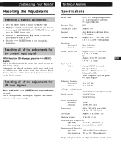
Customizing Your Monitor Resetting the Adjustments Resetting a specific adjustment: 1 Press the MENU button to display the MENU OSD 2 Highlight the OSD containing the adjustment you want to reset using the BRIGHTNESS and CONTRAST buttons and press ...for the current input signal are not reset to the factory settings. TechnicaGl eFtetiantgureSstarted Specifications Picture tube 0.25 - 0.27 mm aperture grill pitch, 21 inches measured diagonally, 90 degree deflection Phosphor Type P22 Transmission Ratio Approx. 39% Faceplate Anti Reflective (AR)/Anti Static (AS) coating Viewable ...
Customizing Your Monitor Resetting the Adjustments Resetting a specific adjustment: 1 Press the MENU button to display the MENU OSD 2 Highlight the OSD containing the adjustment you want to reset using the BRIGHTNESS and CONTRAST buttons and press ...for the current input signal are not reset to the factory settings. TechnicaGl eFtetiantgureSstarted Specifications Picture tube 0.25 - 0.27 mm aperture grill pitch, 21 inches measured diagonally, 90 degree deflection Phosphor Type P22 Transmission Ratio Approx. 39% Faceplate Anti Reflective (AR)/Anti Static (AS) coating Viewable ...
Service Manual
Page 12
...and contrast, are not reset to the factory settings. TechnicaGl eFtetiantgureSstarted Specifications Picture tube 0.25 - 0.27 mm aperture grill pitch, 21 inches measured diagonally, 90 degree deflection Phosphor Type P22 Transmission Ratio Approx. 39% Faceplate Anti Reflective (AR)/Anti Static (AS) ...delay time and the Control Lock function) are reset to the factory settings. Customizing Your Monitor Resetting the Adjustments Resetting a specific adjustment: 1 Press the MENU button to display the MENU OSD 2 Highlight the OSD containing the adjustment you want to reset using the...
...and contrast, are not reset to the factory settings. TechnicaGl eFtetiantgureSstarted Specifications Picture tube 0.25 - 0.27 mm aperture grill pitch, 21 inches measured diagonally, 90 degree deflection Phosphor Type P22 Transmission Ratio Approx. 39% Faceplate Anti Reflective (AR)/Anti Static (AS) ...delay time and the Control Lock function) are reset to the factory settings. Customizing Your Monitor Resetting the Adjustments Resetting a specific adjustment: 1 Press the MENU button to display the MENU OSD 2 Highlight the OSD containing the adjustment you want to reset using the...

Service Manual
Page 19
... single green signal and set at the top and bottom. Note: After the W/B adjustment with the hand degausser. gausser and coil degausser, and the CRT surface with 9300K, measure an average of ΣIk when a full white signal is being operated, it does not satisfy the specification, adjust the ...within the specification given right. 4 corner adjust target : within ± 1 The red and blue must be used on stand-by using a hand degauss while monitor (LCC coil) is entered in the CONT MAX/BRT CENT status. Demagnetize the metal part of the average value. 3. Input AC 230V to 30% of...
... single green signal and set at the top and bottom. Note: After the W/B adjustment with the hand degausser. gausser and coil degausser, and the CRT surface with 9300K, measure an average of ΣIk when a full white signal is being operated, it does not satisfy the specification, adjust the ...within the specification given right. 4 corner adjust target : within ± 1 The red and blue must be used on stand-by using a hand degauss while monitor (LCC coil) is entered in the CONT MAX/BRT CENT status. Demagnetize the metal part of the average value. 3. Input AC 230V to 30% of...
Service Manual
Page 20
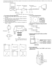
...Convergence Rough Adjustment (1) Receive an image of the white crosshatch signals (white lines on the monitor. YCH H. Run the service software and then follow the instruction. IBM AT Computer as a Jig 1 1-690-391-21 2 A-1500-819-A Interface Unit 3 3-702-691-01 Connector Attachment To BUS CONNECTOR D-...cable of the computer to the connector located on the D board on black). (2) Place the protrusions of the 6-fold poles magnet attached to the CRT neck upon each other. (Fig. 1) (3) Make rough adjustment of the H and V direction convergence by using 4-fold poles magnet. (4) Make...
...Convergence Rough Adjustment (1) Receive an image of the white crosshatch signals (white lines on the monitor. YCH H. Run the service software and then follow the instruction. IBM AT Computer as a Jig 1 1-690-391-21 2 A-1500-819-A Interface Unit 3 3-702-691-01 Connector Attachment To BUS CONNECTOR D-...cable of the computer to the connector located on the D board on black). (2) Place the protrusions of the 6-fold poles magnet attached to the CRT neck upon each other. (Fig. 1) (3) Make rough adjustment of the H and V direction convergence by using 4-fold poles magnet. (4) Make...


