Users Guide
Page 3
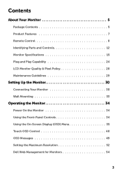
Contents About Your Monitor 5 Package Contents 5 Product Features 7 Remote Control 8 Identifying Parts and Controls 12 Monitor Specifications 15 Plug and Play Capability 24 LCD Monitor Quality & Pixel Policy 28 Maintenance Guidelines 29 Setting Up the Monitor 30 Connecting Your Monitor 30 Wall Mounting 33 Operating the Monitor 34 Power On the Monitor 34 Using the Front-Panel Controls 34 Using the On-Screen Display (OSD) Menu 35 Touch OSD Control 48 OSD Messages 49 Setting the Maximum Resolution 52 Dell Web Management for Monitors 54 3
Contents About Your Monitor 5 Package Contents 5 Product Features 7 Remote Control 8 Identifying Parts and Controls 12 Monitor Specifications 15 Plug and Play Capability 24 LCD Monitor Quality & Pixel Policy 28 Maintenance Guidelines 29 Setting Up the Monitor 30 Connecting Your Monitor 30 Wall Mounting 33 Operating the Monitor 34 Power On the Monitor 34 Using the Front-Panel Controls 34 Using the On-Screen Display (OSD) Menu 35 Touch OSD Control 48 OSD Messages 49 Setting the Maximum Resolution 52 Dell Web Management for Monitors 54 3

Users Guide
Page 6
• LSA1U Wall Mount Kit • Wire Saddle • Power Cable (varies with countries) • VGA Cable • HDMI Cable • DP Cable • USB 3.0 upstream cable (enables the USB ports on the monitor) • Quick Setup Guide • Safety and Regulatory Information 6 About Your Monitor
• LSA1U Wall Mount Kit • Wire Saddle • Power Cable (varies with countries) • VGA Cable • HDMI Cable • DP Cable • USB 3.0 upstream cable (enables the USB ports on the monitor) • Quick Setup Guide • Safety and Regulatory Information 6 About Your Monitor
Users Guide
Page 7
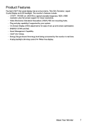
The monitor's features include: • C7017T: 176.563 cm (69.513 in.) agonal viewable image size, 1920 x 1080 resolution, plus full-screen support for lower resolutions. • Video Electronics Standards Association (VESA) 400 mm mounting holes. • Plug and play capability if supported by your system. • On-Screen Display (OSD) adjustments for...
The monitor's features include: • C7017T: 176.563 cm (69.513 in.) agonal viewable image size, 1920 x 1080 resolution, plus full-screen support for lower resolutions. • Video Electronics Standards Association (VESA) 400 mm mounting holes. • Plug and play capability if supported by your system. • On-Screen Display (OSD) adjustments for...
Users Guide
Page 13
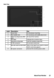
Indicates the connector type. For accessory wire saddle placement. Lists the regulatory approvals. About Your Monitor 13 For remote control use. 7 Barcode serial number label Refer to this label if you need to contact Dell for technical support. 8 AC power connector Connect the monitor power cable. To mount the monitor. Back View Label 1 2 3 4 5 6 Description Screw Hole Wire Saddle hole VESA mounting holes (400 mm) RCA label Regulatory rating label RJ-45 connector Use For Accessory mounting.
Indicates the connector type. For accessory wire saddle placement. Lists the regulatory approvals. About Your Monitor 13 For remote control use. 7 Barcode serial number label Refer to this label if you need to contact Dell for technical support. 8 AC power connector Connect the monitor power cable. To mount the monitor. Back View Label 1 2 3 4 5 6 Description Screw Hole Wire Saddle hole VESA mounting holes (400 mm) RCA label Regulatory rating label RJ-45 connector Use For Accessory mounting.
Users Guide
Page 28
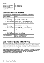
... detract from display quality or usability. A display with packaging Weight (For wall mount or VESA mount considerations - The visible result is considered normal and within competitive standards. In almost...55.5 kg (122.36 lb) Environmental Characteristics The following table lists the environmental conditions for your monitor: Model Number C7017T Temperature • Operating 0 °C to 40 °C (32 °F to 104 °F) • ... Storage: 5 % to 90 % (non-condensing) Shipping: 5 % to see Dell Support site at: http://www.dell.com/support/monitors. 28 About Your Monitor
... detract from display quality or usability. A display with packaging Weight (For wall mount or VESA mount considerations - The visible result is considered normal and within competitive standards. In almost...55.5 kg (122.36 lb) Environmental Characteristics The following table lists the environmental conditions for your monitor: Model Number C7017T Temperature • Operating 0 °C to 40 °C (32 °F to 104 °F) • ... Storage: 5 % to 90 % (non-condensing) Shipping: 5 % to see Dell Support site at: http://www.dell.com/support/monitors. 28 About Your Monitor

Users Guide
Page 33
... INSTRUCTIONS to Wall Plate. Setting Up the Monitor 33 Install Display to that come with LSA1U Wall Mount kit and the VESA-compatible base mounting kit (400 x 400 mm distance). 1. For more information, see the Wall Mount provider website located at http://www.milestone.com/~/media/Files/Chief/Manuals/MSA1U_MTA1U_ LSA1U_LTA1U-I.pdf. Wall...
... INSTRUCTIONS to Wall Plate. Setting Up the Monitor 33 Install Display to that come with LSA1U Wall Mount kit and the VESA-compatible base mounting kit (400 x 400 mm distance). 1. For more information, see the Wall Mount provider website located at http://www.milestone.com/~/media/Files/Chief/Manuals/MSA1U_MTA1U_ LSA1U_LTA1U-I.pdf. Wall...

Installation Guide MSA1U MTA1U LSA1U LTA1U-I
Page 1
INSTALLATION INSTRUCTIONS MSA1U MTA1U LSA1U LTA1U FUSION MEDIUM AND LARGE FLAT PANEL MOUNTS MSA1U/MTA1U/LSA1U/LTA1U
INSTALLATION INSTRUCTIONS MSA1U MTA1U LSA1U LTA1U FUSION MEDIUM AND LARGE FLAT PANEL MOUNTS MSA1U/MTA1U/LSA1U/LTA1U
Installation Guide MSA1U MTA1U LSA1U LTA1U-I
Page 2
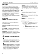
...document. Chief® is the installer's responsibility to make this manual accurate and complete. All rights reserved. Return the mounting system to which an accessory and/or component is attached. It is a registered trademark of Milestone AV Technologies. DEFINITIONS ...COMPONENT is subject to equipment! IMPORTANT SAFETY INSTRUCTIONS WARNING: Failure to read, thoroughly understand, and follow the instructions. MOUNTING SYSTEM: A MOUNTING SYSTEM is the primary Chief product to a service center for every possible contingency in serious personal injury or damage ...
...document. Chief® is the installer's responsibility to make this manual accurate and complete. All rights reserved. Return the mounting system to which an accessory and/or component is attached. It is a registered trademark of Milestone AV Technologies. DEFINITIONS ...COMPONENT is subject to equipment! IMPORTANT SAFETY INSTRUCTIONS WARNING: Failure to read, thoroughly understand, and follow the instructions. MOUNTING SYSTEM: A MOUNTING SYSTEM is the primary Chief product to a service center for every possible contingency in serious personal injury or damage ...

Installation Guide MSA1U MTA1U LSA1U LTA1U-I
Page 3
... RECESSED APPLICATIONS, MINIMUM VERTICAL LIFT FOR HOOK ENGAGEMENT IS .75" (19 mm) DIMENSIONS: INCHES [MILLIMETERS] 3 MAXIMUM MOUNTING PATTERN IS 25.3" (642 mm) WITH REVERSING UPRIGHTS 3. MAXIMUM MOUNTING PATTERN IS 25.6" (650 mm) WITH REVERSING UPRIGHTS 3. MAXIMUM MOUNTING PATTERN IS 22.7" (576 mm) WITHOUT REVERSING UPRIGHTS 2. Installation Instructions DIMENSIONS MSA1U/MTA1U/LSA1U/LTA1U MSA1U...
... RECESSED APPLICATIONS, MINIMUM VERTICAL LIFT FOR HOOK ENGAGEMENT IS .75" (19 mm) DIMENSIONS: INCHES [MILLIMETERS] 3 MAXIMUM MOUNTING PATTERN IS 25.3" (642 mm) WITH REVERSING UPRIGHTS 3. MAXIMUM MOUNTING PATTERN IS 25.6" (650 mm) WITH REVERSING UPRIGHTS 3. MAXIMUM MOUNTING PATTERN IS 22.7" (576 mm) WITHOUT REVERSING UPRIGHTS 2. Installation Instructions DIMENSIONS MSA1U/MTA1U/LSA1U/LTA1U MSA1U...

Installation Guide MSA1U MTA1U LSA1U LTA1U-I
Page 4
MAXIMUM MOUNTING PATTERN IS 31.25" (794 mm) WITHOUT REVERSING UPRIGHTS 2. FOR RECESSED APPLICATIONS, MINIMUM VERTICAL LIFT FOR HOOK ENGAGEMENT IS .75" (19 mm) 4 DIMENSIONS: INCHES [MILLIMETERS] LTA1U DIMENSIONS: INCHES [MILLIMETERS] MSA1U/MTA1U/LSA1U/LTA1U DIMENSIONS--continued 1.45 36.9 6.00 152.4 Installation Instructions LSA1U 15.00 381.0 6.00 152.4 16.00 406.3 MINIMUM UPRIGHT SPACING RAILS CAN BE SLID LEFT OR RIGHT FOR OFFSET 1. MAXIMUM MOUNTING PATTERN IS 34.6" (879 mm) WITH REVERSING UPRIGHTS 3.
MAXIMUM MOUNTING PATTERN IS 31.25" (794 mm) WITHOUT REVERSING UPRIGHTS 2. FOR RECESSED APPLICATIONS, MINIMUM VERTICAL LIFT FOR HOOK ENGAGEMENT IS .75" (19 mm) 4 DIMENSIONS: INCHES [MILLIMETERS] LTA1U DIMENSIONS: INCHES [MILLIMETERS] MSA1U/MTA1U/LSA1U/LTA1U DIMENSIONS--continued 1.45 36.9 6.00 152.4 Installation Instructions LSA1U 15.00 381.0 6.00 152.4 16.00 406.3 MINIMUM UPRIGHT SPACING RAILS CAN BE SLID LEFT OR RIGHT FOR OFFSET 1. MAXIMUM MOUNTING PATTERN IS 34.6" (879 mm) WITH REVERSING UPRIGHTS 3.

Installation Guide MSA1U MTA1U LSA1U LTA1U-I
Page 6
... hardware box] A (4) B (4) M4x12mm M4x20mm C (4) M4x25mm D (4) E (4) F (4) M5x12mm M5x20mm M5x25mm G (4) M6x12mm H (4) M6x20mm I (4) M6x25mm J (4) K (4) L (4) M8x12mm M8x20mm M8x30mm MA (8) [Nesting spacer] MB (4) [Universal washer] MSA1/LSA1 Mount Hardware Kit MTA1/LTA1 Mount Hardware Kit Wall Mounting Hardware Kit N (4) P (4) 5/16 x 2-1/2" UX10x60mm Q (4) [Slotted washer] R (1) 3/16" S (2) 3/8-16 x 3/4" [Included in hardware box] R (1) 3/16" S (2) 3/8-16 x 3/4" U (2) 1/4-20 T (2) 1/4-20 x 1" [Included in hardware box] V (1) [left...
... hardware box] A (4) B (4) M4x12mm M4x20mm C (4) M4x25mm D (4) E (4) F (4) M5x12mm M5x20mm M5x25mm G (4) M6x12mm H (4) M6x20mm I (4) M6x25mm J (4) K (4) L (4) M8x12mm M8x20mm M8x30mm MA (8) [Nesting spacer] MB (4) [Universal washer] MSA1/LSA1 Mount Hardware Kit MTA1/LTA1 Mount Hardware Kit Wall Mounting Hardware Kit N (4) P (4) 5/16 x 2-1/2" UX10x60mm Q (4) [Slotted washer] R (1) 3/16" S (2) 3/8-16 x 3/4" [Included in hardware box] R (1) 3/16" S (2) 3/8-16 x 3/4" U (2) 1/4-20 T (2) 1/4-20 x 1" [Included in hardware box] V (1) [left...

Installation Guide MSA1U MTA1U LSA1U LTA1U-I
Page 7
... 4. Proceed to Attaching Interface Brackets to a bare 8" concrete, 8"x8"x16" concrete block; The MTA1U and LTA1U have static brackets which the mount is being attached is capable of supporting five times the combined weight of screen 7" (177.8mm) 5. NOTE: Proceed to either the left and... stud to either the Installing to a Wood Stud Wall section or the Installing to -side for proper location. 9. Drill 7/32" (5.5mm) pilot holes at upper mounting slots. 9 (Q) x 2 7 (N) x 2 10 56 (Z) 11 12 13 (Q) x 2 13 (N) x 2 (MSA1U shown) Figure 2 11. or 2" x 4" wood studs (16" on center ...
... 4. Proceed to Attaching Interface Brackets to a bare 8" concrete, 8"x8"x16" concrete block; The MTA1U and LTA1U have static brackets which the mount is being attached is capable of supporting five times the combined weight of screen 7" (177.8mm) 5. NOTE: Proceed to either the left and... stud to either the Installing to a Wood Stud Wall section or the Installing to -side for proper location. 9. Drill 7/32" (5.5mm) pilot holes at upper mounting slots. 9 (Q) x 2 7 (N) x 2 10 56 (Z) 11 12 13 (Q) x 2 13 (N) x 2 (MSA1U shown) Figure 2 11. or 2" x 4" wood studs (16" on center ...

Installation Guide MSA1U MTA1U LSA1U LTA1U-I
Page 8
... Drill one slotted washer (Q) over lag bolts and adjust side-to approximate center of screen location. Mark the attachment points for lower mounting holes. (See Figure 3) WARNING: IMPROPER INSTALLATION CAN LEAD TO DISPLAY FALLING CAUSING SERIOUS PERSONAL INJURY OR DAMAGE TO EQUIPMENT! Drill ...3/8" x 3-1/2" (9.5mm x 88.9mm) pilot holes at upper mounting slots. 11. Select correct screws, nesting spacers (if necessary) and universal washers from the center point to wall. 8. MSA1U/MTA1U...
... Drill one slotted washer (Q) over lag bolts and adjust side-to approximate center of screen location. Mark the attachment points for lower mounting holes. (See Figure 3) WARNING: IMPROPER INSTALLATION CAN LEAD TO DISPLAY FALLING CAUSING SERIOUS PERSONAL INJURY OR DAMAGE TO EQUIPMENT! Drill ...3/8" x 3-1/2" (9.5mm x 88.9mm) pilot holes at upper mounting slots. 11. Select correct screws, nesting spacers (if necessary) and universal washers from the center point to wall. 8. MSA1U/MTA1U...

Installation Guide MSA1U MTA1U LSA1U LTA1U-I
Page 9
... bracket knobs may be switched to allow the interface brackets (X and Y) to be switched, with the knobs on the inside of the mount. (See Figure 6) 3. Remove interface brackets from mount. Hold the right interface bracket horizontally, tightly gripping it so that spacers do not move. Repeat Steps 3c through 3f with the... Figure 5) (Single) (Nested) (Stacked) 0.375 [9.5] 0.563 [14.3] 0.750 [19.1] Figure 5 Switching Interface Brackets (Optional) If an installation situation makes adjusting the location of the wall mount.
... bracket knobs may be switched to allow the interface brackets (X and Y) to be switched, with the knobs on the inside of the mount. (See Figure 6) 3. Remove interface brackets from mount. Hold the right interface bracket horizontally, tightly gripping it so that spacers do not move. Repeat Steps 3c through 3f with the... Figure 5) (Single) (Nested) (Stacked) 0.375 [9.5] 0.563 [14.3] 0.750 [19.1] Figure 5 Switching Interface Brackets (Optional) If an installation situation makes adjusting the location of the wall mount.

Installation Guide MSA1U MTA1U LSA1U LTA1U-I
Page 10
Both interface brackets must NEVER be located on same side of wall bracket. (See Figure 8) Center Line (CL) Installation Instructions NEVER place both interface brackets (V and W or X and Y) to be located to one side of the wall mount center line (CL)! MSA1U/MTA1U/LSA1U/LTA1U Attaching Screen to Wall Mount NOTE: NEVER place both interface brackets (V and W or X and Y) to one side of the wall mount center line! (See Figure 8) NOTE: Do NOT allow both interface brackets to one side of the wall brackets! [Brackets V and W shown] Figure 8 10
Both interface brackets must NEVER be located on same side of wall bracket. (See Figure 8) Center Line (CL) Installation Instructions NEVER place both interface brackets (V and W or X and Y) to be located to one side of the wall mount center line (CL)! MSA1U/MTA1U/LSA1U/LTA1U Attaching Screen to Wall Mount NOTE: NEVER place both interface brackets (V and W or X and Y) to one side of the wall mount center line! (See Figure 8) NOTE: Do NOT allow both interface brackets to one side of the wall brackets! [Brackets V and W shown] Figure 8 10

Installation Guide MSA1U MTA1U LSA1U LTA1U-I
Page 11
...8226; MTA1U / LTA1U: Move latch on the pull cords and swing inward toward wall, latching interface brackets to lower rail and fastening bottom of the mount (Z). (See Figure 9) NOTE: The screen initially installs into the "service mode" to desired viewing position. 3. Route cables between wall and rails. Pull...downward on top of interface bracket to OPEN position and hang top hook of interface brackets (X and Y) onto the top rail of screen to mount so it does not extend beyond bottom of pinch point areas. 4. CAUTION: PINCH POINTS! Adjust screen and rails to allow easy cable access....
...8226; MTA1U / LTA1U: Move latch on the pull cords and swing inward toward wall, latching interface brackets to lower rail and fastening bottom of the mount (Z). (See Figure 9) NOTE: The screen initially installs into the "service mode" to desired viewing position. 3. Route cables between wall and rails. Pull...downward on top of interface bracket to OPEN position and hang top hook of interface brackets (X and Y) onto the top rail of screen to mount so it does not extend beyond bottom of pinch point areas. 4. CAUTION: PINCH POINTS! Adjust screen and rails to allow easy cable access....

Installation Guide MSA1U MTA1U LSA1U LTA1U-I
Page 12
...be locked at 0°, 6° or 12° using one 1/4-20 x 1" round head carriage bolt (T) and one side of the wall mount center line! (See Figure 8) NOTE: Do NOT allow from -2° to 12° tilt, and can be adjusted along rails side to ...1 1" (25.4mm) horizontal adjustment possible Figure 10 2. Loosen the interface bracket knob. 2. MSA1U/MTA1U/LSA1U/LTA1U Adjustments Horizontal Adjustment 3 (U) 1. The mount wall brackets may also be locked at 12° tilt Figure 11 12 Lock at 0° tilt Installation Instructions Latch in CLOSED position (T) Interface bracket...
...be locked at 0°, 6° or 12° using one 1/4-20 x 1" round head carriage bolt (T) and one side of the wall mount center line! (See Figure 8) NOTE: Do NOT allow from -2° to 12° tilt, and can be adjusted along rails side to ...1 1" (25.4mm) horizontal adjustment possible Figure 10 2. Loosen the interface bracket knob. 2. MSA1U/MTA1U/LSA1U/LTA1U Adjustments Horizontal Adjustment 3 (U) 1. The mount wall brackets may also be locked at 12° tilt Figure 11 12 Lock at 0° tilt Installation Instructions Latch in CLOSED position (T) Interface bracket...

Installation Guide MSA1U MTA1U LSA1U LTA1U-I
Page 13
...) (front view) Figure 12 1 Padlock shackle maximum diameter: - 5/16" (7.9mm) Figure 13 13 Installation Instructions Locking Screen Interface Brackets (Optional) 1. Lock screen interface brackets onto mount rails using one 3/8-16 x 3/4" set screw (S) on each interface bracket. (See Figure 12) 1 (S) x 2 (MSA1U / LSA1U) (back view) MSA1U/MTA1U/LSA1U/LTA1U Locking...
...) (front view) Figure 12 1 Padlock shackle maximum diameter: - 5/16" (7.9mm) Figure 13 13 Installation Instructions Locking Screen Interface Brackets (Optional) 1. Lock screen interface brackets onto mount rails using one 3/8-16 x 3/4" set screw (S) on each interface bracket. (See Figure 12) 1 (S) x 2 (MSA1U / LSA1U) (back view) MSA1U/MTA1U/LSA1U/LTA1U Locking...


