
Mobile Manual
Page 3
... LAPTOP 15 Left View Features 16 Right View Features 17 Back View Features 18 Computer Base and Keyboard Features 20 Status Lights 21 Media Control Keys 21 Power Button 22 Function Keys 23 CHAPTER 3: USING YOUR LAPTOP 25 Alienware Command Center 26 Connecting External Displays 26 Using Removable Media and Cards 27...
... LAPTOP 15 Left View Features 16 Right View Features 17 Back View Features 18 Computer Base and Keyboard Features 20 Status Lights 21 Media Control Keys 21 Power Button 22 Function Keys 23 CHAPTER 3: USING YOUR LAPTOP 25 Alienware Command Center 26 Connecting External Displays 26 Using Removable Media and Cards 27...

Mobile Manual
Page 18
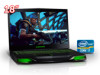
Back View Features 1 1 AC adapter connector - Connects to the AC adapter to power the computer and charge the battery. 18 CHAPTER 2: GETTING TO KNOW YOUR LAPTOP
Back View Features 1 1 AC adapter connector - Connects to the AC adapter to power the computer and charge the battery. 18 CHAPTER 2: GETTING TO KNOW YOUR LAPTOP

Mobile Manual
Page 63
... Center" on page 26. CHAPTER 7: SPECIFICATIONS 63 colors can be changed by invoking the AlienFX application in the Alienware Command Center. M and type - H) • Hi Density-SD (SDHD) • Hi Capacity-SD (SDHC) Display Type Maximum resolution Dimensions (active area) Height Width Diagonal ...Refresh rate Operating angle Pixel pitch Controls Keyboard (Backlit) Number of keys Backlight color 18.4 inch FHD WLED TrueLife 1920 x 1080 230.04 mm (9.06 inches) 408.96 mm (16.10 inches) 469.22 mm...
... Center" on page 26. CHAPTER 7: SPECIFICATIONS 63 colors can be changed by invoking the AlienFX application in the Alienware Command Center. M and type - H) • Hi Density-SD (SDHD) • Hi Capacity-SD (SDHC) Display Type Maximum resolution Dimensions (active area) Height Width Diagonal ...Refresh rate Operating angle Pixel pitch Controls Keyboard (Backlit) Number of keys Backlight color 18.4 inch FHD WLED TrueLife 1920 x 1080 230.04 mm (9.06 inches) 408.96 mm (16.10 inches) 469.22 mm...

Service Manual
Page 22
... cables through the routing guides on the palm-rest assembly. 4. Place the display assembly in position and replace the two screws, on the computer base. 18. Replace the macro keyboard (see Replacing the Keyboard). 12. Close the display and turn the computer over . 10. Failure to the Mini-Card (see Replacing...
... cables through the routing guides on the palm-rest assembly. 4. Place the display assembly in position and replace the two screws, on the computer base. 18. Replace the macro keyboard (see Replacing the Keyboard). 12. Close the display and turn the computer over . 10. Failure to the Mini-Card (see Replacing...

Service Manual
Page 49
... Power-Button Board). 3. Remove the power-button board (see Removing the Status-Light Board). Remove the status-light board (see Removing the Power-Button Board). 18. Turn the computer over . 13.
... Power-Button Board). 3. Remove the power-button board (see Removing the Status-Light Board). Remove the status-light board (see Removing the Power-Button Board). 18. Turn the computer over . 13.

Service Manual
Page 57
... 7. Remove the keyboard (see Removing the Video Card(s)). 19. Remove the Bluetooth card (see Removing the Palm Rest). 14. Sink(s)). 18. Damage due to servicing that shipped with your warranty. Removing the System Board 1. Remove the palm-rest assembly (see Removing the Bluetooth ...www.dell.com/regulatory_compliance. Remove the video-card heat-sink(s) (see Removing the Processor Module). The system board's BIOS chip contains the Service Tag, which is not covered by their edges, and avoid touching pins and contacts. Back to Contents Page System Board Alienware M18x ...
... 7. Remove the keyboard (see Removing the Video Card(s)). 19. Remove the Bluetooth card (see Removing the Palm Rest). 14. Sink(s)). 18. Damage due to servicing that shipped with your warranty. Removing the System Board 1. Remove the palm-rest assembly (see Removing the Bluetooth ...www.dell.com/regulatory_compliance. Remove the video-card heat-sink(s) (see Removing the Processor Module). The system board's BIOS chip contains the Service Tag, which is not covered by their edges, and avoid touching pins and contacts. Back to Contents Page System Board Alienware M18x ...

Service Manual
Page 59
... Video Card(s)). 11. Replace the center control cover (see Replacing the Palm Rest). 14. Replace the palm-rest assembly (see Replacing the Center Control Cover). 18. Connect the video card heat-sink fan cable to enter the system setup program. 4. Entering the Service Tag in and that the main battery is...
... Video Card(s)). 11. Replace the center control cover (see Replacing the Palm Rest). 14. Replace the palm-rest assembly (see Replacing the Center Control Cover). 18. Connect the video card heat-sink fan cable to enter the system setup program. 4. Entering the Service Tag in and that the main battery is...


