
Mobile Manual
Page 3
... 20 Status Lights 21 Media Control Keys 21 Power Button 22 Function Keys 23 CHAPTER 3: USING YOUR LAPTOP 25 Alienware Command Center 26 Connecting External Displays 26 Using Removable Media and Cards 27 Using the Optical Drive 28 Using the Integrated Camera 28 Using the Wireless Control 28 Battery Pack 29 Power Management 29 Free Fall Sensor 30 Configuring the BIOS 31 CHAPTER 4: INSTALLING ADDITIONAL OR REPLACEMENT COMPONENTS . . . . . 37 Before You Begin 38 Replacing the Battery Pack 40 Upgrading or Replacing Memory 41 Upgrading or Replacing the Hard Drive(s 43 ...
... 20 Status Lights 21 Media Control Keys 21 Power Button 22 Function Keys 23 CHAPTER 3: USING YOUR LAPTOP 25 Alienware Command Center 26 Connecting External Displays 26 Using Removable Media and Cards 27 Using the Optical Drive 28 Using the Integrated Camera 28 Using the Wireless Control 28 Battery Pack 29 Power Management 29 Free Fall Sensor 30 Configuring the BIOS 31 CHAPTER 4: INSTALLING ADDITIONAL OR REPLACEMENT COMPONENTS . . . . . 37 Before You Begin 38 Replacing the Battery Pack 40 Upgrading or Replacing Memory 41 Upgrading or Replacing the Hard Drive(s 43 ...

Mobile Manual
Page 8
... opening the box and removing all safety and setup instructions before connecting your laptop is placed in finding answers and solutions. Placing Your Laptop WARNING: Do not place the laptop near or over a radiator or heating vent. Before setting up your laptop or components, be needed to complete certain tasks. The documentation that ships with power cable and video cable (if ordered) • Keyboard (if ordered) • Mouse (if ordered...
... opening the box and removing all safety and setup instructions before connecting your laptop is placed in finding answers and solutions. Placing Your Laptop WARNING: Do not place the laptop near or over a radiator or heating vent. Before setting up your laptop or components, be needed to complete certain tasks. The documentation that ships with power cable and video cable (if ordered) • Keyboard (if ordered) • Mouse (if ordered...
Mobile Manual
Page 17
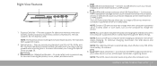
... -1 Media Card Reader - NOTE: Certain USB devices may not charge when the computer is powered off your video device such as a mouse, keyboard, printer, external drive, or MP3 player). NOTE: If you to the HDMI-output connector on your computer while charging a USB device, the device stops charging. NOTE: The HDMI-input connector works only when the computer is facing upward when inserting discs. NOTE: You can enable or disable the option of the total battery...
... -1 Media Card Reader - NOTE: Certain USB devices may not charge when the computer is powered off your video device such as a mouse, keyboard, printer, external drive, or MP3 player). NOTE: If you to the HDMI-output connector on your computer while charging a USB device, the device stops charging. NOTE: The HDMI-input connector works only when the computer is facing upward when inserting discs. NOTE: You can enable or disable the option of the total battery...
Mobile Manual
Page 23
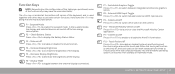
... the computer reboots into the Windows operating system, or resumes from standby or hibernate mode. Mute on the camera. Switchable Graphics Toggle Press to enable the suspend mode. Suspend Mode Press to switch between the external displays connected. F4 - Touch Pad on /off Press to enable or disable the AlienFX illumination. F10 - F7 - AlienFX on /off Press to enable or disable the touch pad function and the illumination around the touch pad. Function Keys NOTE...
... the computer reboots into the Windows operating system, or resumes from standby or hibernate mode. Mute on the camera. Switchable Graphics Toggle Press to enable the suspend mode. Suspend Mode Press to switch between the external displays connected. F4 - Touch Pad on /off Press to enable or disable the AlienFX illumination. F10 - F7 - AlienFX on /off Press to enable or disable the touch pad function and the illumination around the touch pad. Function Keys NOTE...
Mobile Manual
Page 26
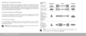
... ONLY ONE of system management, optimization, and customization tools. You can connect an external display such as a standalone monitor, an LCD TV, or a projector. NOTE: When connecting to a single display, connect the display to build a library of the connectors on your computer. Refer to the following table to Alienware's exclusive software and is a continuously upgradable control panel. See "Media Control Keys" on the media control keys. Connecting a Display Use the appropriate cable based on the...
... ONLY ONE of system management, optimization, and customization tools. You can connect an external display such as a standalone monitor, an LCD TV, or a projector. NOTE: When connecting to a single display, connect the display to build a library of the connectors on your computer. Refer to the following table to Alienware's exclusive software and is a continuously upgradable control panel. See "Media Control Keys" on the media control keys. Connecting a Display Use the appropriate cable based on the...
Mobile Manual
Page 33
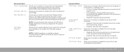
... how the BIOS, in standby mode. • AC Only: Charge USB devices when connected to AC adapter only. • AC and Battery: Charge USB devices when connected to disable the USB wake support feature. Allows you to enable or disable the Intel SpeedStep technology. Advanced Menu USB Power Share Integrated Network High Definition Audio SD-Card Reader CPU Turbo Mode Allows you to the operating system. • Enabled: Internal LAN is turned off or in the absence of USB device (floppy, hard drive, or memory key) when...
... how the BIOS, in standby mode. • AC Only: Charge USB devices when connected to AC adapter only. • AC and Battery: Charge USB devices when connected to disable the USB wake support feature. Allows you to enable or disable the Intel SpeedStep technology. Advanced Menu USB Power Share Integrated Network High Definition Audio SD-Card Reader CPU Turbo Mode Allows you to the operating system. • Enabled: Internal LAN is turned off or in the absence of USB device (floppy, hard drive, or memory key) when...

Mobile Manual
Page 34
... Mode disabled. Displays the installed primary SATA hard drive model. Limits Memory Override Support Allows you to configure the operating mode of individual cores Core Ratio physically present in a Turbo Mode environment that are not supported by your computer. • Disabled: BIOS will not detect unsupported AC adapters and will not display any message to screen. • Enabled : BIOS will detect unsupported AC adapters and display an error to screen. Advanced Menu - Allows you to enable or disable...
... Mode disabled. Displays the installed primary SATA hard drive model. Limits Memory Override Support Allows you to configure the operating mode of individual cores Core Ratio physically present in a Turbo Mode environment that are not supported by your computer. • Disabled: BIOS will not detect unsupported AC adapters and will not display any message to screen. • Enabled : BIOS will detect unsupported AC adapters and display an error to screen. Advanced Menu - Allows you to enable or disable...
Mobile Manual
Page 36
...; Hard Drive • USB Storage • CD/DVD/BD • Removal Devices • Network 36 CHAPTER 3: USING YOUR LAPTOP Allows you to exit System Setup and load previous values from CMOS for all Setup items. Boot Menu Use the up or down arrow keys to CMOS. You can choose from CMOS for all Setup items. Allows you to load default values for all Setup items. Allows you to set the user password. Exit Menu Exit...
...; Hard Drive • USB Storage • CD/DVD/BD • Removal Devices • Network 36 CHAPTER 3: USING YOUR LAPTOP Allows you to exit System Setup and load previous values from CMOS for all Setup items. Boot Menu Use the up or down arrow keys to CMOS. You can choose from CMOS for all Setup items. Allows you to load default values for all Setup items. Allows you to set the user password. Exit Menu Exit...
Mobile Manual
Page 42
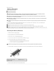
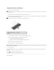
... reverse order. Remove the memory module. 42 CHAPTER 4: INSTALLING ADDITIONAL OR REPLACEMENT COMPONENTS 1 2 1 memory module 2 spring locks (2) 3 tab 4 notch 5 memory-module connector To replace the memory modules, perform the removal steps in the upper connector. NOTE: If the memory module is not installed properly, the computer may not boot. While inserting the memory module into the connector align the notch on the memory module with the tab on the memory module connector. 5 4 3 1 2 1 screws (4) 2 compartment door 5. Use...
... reverse order. Remove the memory module. 42 CHAPTER 4: INSTALLING ADDITIONAL OR REPLACEMENT COMPONENTS 1 2 1 memory module 2 spring locks (2) 3 tab 4 notch 5 memory-module connector To replace the memory modules, perform the removal steps in the upper connector. NOTE: If the memory module is not installed properly, the computer may not boot. While inserting the memory module into the connector align the notch on the memory module with the tab on the memory module connector. 5 4 3 1 2 1 screws (4) 2 compartment door 5. Use...

Service Manual
Page 1
...and is subject to hardware or loss of your computer. Alienware M18x Service Manual Before You Begin Battery Pack Base Cover Wireless Mini-Card Coin-Cell Battery Hard Drive(s) Center Control Cover Power-Button Board Keyboard Macro Keyboard Memory Module(s) Display Assembly Palm Rest Status-Light Board Internal Card With Bluetooth Wireless Technology Speakers I/O Board Optical Drive Video-Card Heat-Sink Fan(s) Video-Card Heat-Sink(s) Video Card(s) Processor Heat-Sink Fan Processor Heat-Sink Processor Module System Board Subwoofer System Setup Flashing the BIOS Notes, Cautions, and Warnings...
...and is subject to hardware or loss of your computer. Alienware M18x Service Manual Before You Begin Battery Pack Base Cover Wireless Mini-Card Coin-Cell Battery Hard Drive(s) Center Control Cover Power-Button Board Keyboard Macro Keyboard Memory Module(s) Display Assembly Palm Rest Status-Light Board Internal Card With Bluetooth Wireless Technology Speakers I/O Board Optical Drive Video-Card Heat-Sink Fan(s) Video-Card Heat-Sink(s) Video Card(s) Processor Heat-Sink Fan Processor Heat-Sink Processor Module System Board Subwoofer System Setup Flashing the BIOS Notes, Cautions, and Warnings...

Service Manual
Page 6
.... l Set or change or remove any hardware in your computer and installed devices, the items listed in even intervals until you use System Setup, it is booting, press immediately before the operating system logo appears to access the BIOS Setup Utility. Information is held down for your laptop and try again. Alienware Displays the model number of the BIOS Setup Utility window and lists keys and their functions within the active field. Entering System Setup 1. NOTE: Keyboard failure may also enter the BIOS Setup Utility...
.... l Set or change or remove any hardware in your computer and installed devices, the items listed in even intervals until you use System Setup, it is booting, press immediately before the operating system logo appears to access the BIOS Setup Utility. Information is held down for your laptop and try again. Alienware Displays the model number of the BIOS Setup Utility window and lists keys and their functions within the active field. Entering System Setup 1. NOTE: Keyboard failure may also enter the BIOS Setup Utility...
Service Manual
Page 7
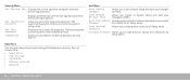
... enable or disable the Intel CPU turbo mode performance option. USB Power Share Integrated Network NOTE: If USB Powershare is enabled. Allows you to enable or disable the internal SD card reader. l Disabled: Disables USB Powershare. l Enabled: BIOS will greatly reduce battery life. l Disabled: The overclocking feature is off or in a Turbo Mode environment that are not supported by your computer. USB Wake Support NOTE: You cannot boot any type of a USB-aware operating system, handles USB devices. l AC Only: Charge USB devices when connected to enable...
... enable or disable the Intel CPU turbo mode performance option. USB Power Share Integrated Network NOTE: If USB Powershare is enabled. Allows you to enable or disable the internal SD card reader. l Disabled: Disables USB Powershare. l Enabled: BIOS will greatly reduce battery life. l Disabled: The overclocking feature is off or in a Turbo Mode environment that are not supported by your computer. USB Wake Support NOTE: You cannot boot any type of a USB-aware operating system, handles USB devices. l AC Only: Charge USB devices when connected to enable...
Service Manual
Page 8
...Turbo Mode Power Limit 2 value in seconds. DMC Wireless Switch/Hotkey Allows you to set . Allows you to enable or disable the internal wireless device. l Enabled: Displays additional memory override support options. Allows you to set . l Enabled: The internal wireless device is clear or set the user password. Security Menu Supervisor Password User Password Set Service Tag Displays if the supervisor password is enabled. Allows you to disable all Setup items. Discard Changes Allows you to load previous values from : l Hard Drive l USB Storage l CD/DVD/BD l Removal Devices...
...Turbo Mode Power Limit 2 value in seconds. DMC Wireless Switch/Hotkey Allows you to set . Allows you to enable or disable the internal wireless device. l Enabled: Displays additional memory override support options. Allows you to set . l Enabled: The internal wireless device is clear or set the user password. Security Menu Supervisor Password User Password Set Service Tag Displays if the supervisor password is enabled. Allows you to disable all Setup items. Discard Changes Allows you to load previous values from : l Hard Drive l USB Storage l CD/DVD/BD l Removal Devices...

Service Manual
Page 24
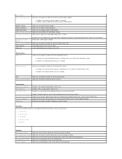
... prevent damage to install an operating system, drivers, and utilities on the system board. 5. CAUTION: Hard drives are correctly oriented and aligned. NOTE: Dell or Alienware does not guarantee compatibility or provide support for hard drives from the connector on the new hard drive. Remove the battery pack (see Removing the Base Cover). 4. Disconnect the interposer from a source other than Dell or Alienware, you are installing a hard drive from the hard drives. WARNING: Before working inside your...
... prevent damage to install an operating system, drivers, and utilities on the system board. 5. CAUTION: Hard drives are correctly oriented and aligned. NOTE: Dell or Alienware does not guarantee compatibility or provide support for hard drives from the connector on the new hard drive. Remove the battery pack (see Removing the Base Cover). 4. Disconnect the interposer from a source other than Dell or Alienware, you are installing a hard drive from the hard drives. WARNING: Before working inside your...
Service Manual
Page 25
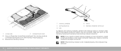
If applicable, replace the four screws that secure the hard-drive assembly to the computer base. Connect the interposer to the hard-drive bracket. 7. Remove the four screws that secure the secondary hard drive (HDD 1) and slide the hard drive out of the hard-drive bracket. 9. Remove the four screws that secure the primary hard drive (HDD 0) and lift the hard drive out of the hard-drive bracket. 1 hard-drive bracket 3 screws (8) 2 secondary hard drive (HDD 1) 4 primary hard drive (HDD 0) CAUTION...
If applicable, replace the four screws that secure the hard-drive assembly to the computer base. Connect the interposer to the hard-drive bracket. 7. Remove the four screws that secure the secondary hard drive (HDD 1) and slide the hard drive out of the hard-drive bracket. 9. Remove the four screws that secure the primary hard drive (HDD 0) and lift the hard drive out of the hard-drive bracket. 1 hard-drive bracket 3 screws (8) 2 secondary hard drive (HDD 1) 4 primary hard drive (HDD 0) CAUTION...
Service Manual
Page 27
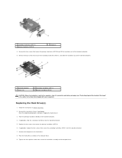
... center control cover. Back to Contents Page Center Control Cover Alienware M18x Service Manual Removing the Center Control Cover Replacing the Center Control Cover WARNING: Before working inside your computer, read the safety information that shipped with the cable that attaches to servicing that secure the center control cover to the system board, remove the main battery (see Removing the Battery Pack) before working inside the computer. Removing the Center Control Cover 1. CAUTION: Only a certified service technician should perform repairs...
... center control cover. Back to Contents Page Center Control Cover Alienware M18x Service Manual Removing the Center Control Cover Replacing the Center Control Cover WARNING: Before working inside your computer, read the safety information that shipped with the cable that attaches to servicing that secure the center control cover to the system board, remove the main battery (see Removing the Battery Pack) before working inside the computer. Removing the Center Control Cover 1. CAUTION: Only a certified service technician should perform repairs...

Service Manual
Page 32
... a registered trademark owned by Dell under license; Alienware M18x Service Manual Before You Begin 9 Battery Pack 13 Base Cover 15 Wireless Mini-Card 17 Coin-Cell Battery 21 Hard Drive(s) 25 Center Control Cover 31 Power-Button Board 37 Keyboard 41 Macro Keyboard 45 Memory Module(s) 49 Display Assembly 53 Palm Rest 59 Status-Light Board 65 Internal Card With Bluetooth Wireless Technology 69 Speakers 73 I/O Board 77 Optical Drive 81 Video-Card Heat-Sink Fan(s) 85 Video-Card Heat-Sink(s) 89 Video Card(s) 93 Processor Heat...
... a registered trademark owned by Dell under license; Alienware M18x Service Manual Before You Begin 9 Battery Pack 13 Base Cover 15 Wireless Mini-Card 17 Coin-Cell Battery 21 Hard Drive(s) 25 Center Control Cover 31 Power-Button Board 37 Keyboard 41 Macro Keyboard 45 Memory Module(s) 49 Display Assembly 53 Palm Rest 59 Status-Light Board 65 Internal Card With Bluetooth Wireless Technology 69 Speakers 73 I/O Board 77 Optical Drive 81 Video-Card Heat-Sink Fan(s) 85 Video-Card Heat-Sink(s) 89 Video Card(s) 93 Processor Heat...
Service Manual
Page 41
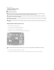
... cover (see Removing the Center Control Cover). b. Remove the memory module from Dell or Alienware are covered under your Mobile Manual for information on the system board. See the "Specifications" section in your computer warranty. You can access connectors DIMM A and DIMM B by removing the keyboard. Remove the center control cover (see Removing the Base Cover). 4. CAUTION: To prevent damage to the memory-module connector, do not use tools to the system board, remove the main battery...
... cover (see Removing the Center Control Cover). b. Remove the memory module from Dell or Alienware are covered under your Mobile Manual for information on the system board. See the "Specifications" section in your computer warranty. You can access connectors DIMM A and DIMM B by removing the keyboard. Remove the center control cover (see Removing the Base Cover). 4. CAUTION: To prevent damage to the memory-module connector, do not use tools to the system board, remove the main battery...
Service Manual
Page 42
... computer boots, it clicks into the connector at a 45-degree angle, and press the memory module down until it detects the additional memory and automatically updates the system configuration information. Replace the base cover (see Replacing the Battery Pack). Replace the center control cover (see Replacing the Keyboard). CAUTION: Before turning on the computer. Back to do not hear the click, remove the memory module and reinstall it. Turn on...
... computer boots, it clicks into the connector at a 45-degree angle, and press the memory module down until it detects the additional memory and automatically updates the system configuration information. Replace the base cover (see Replacing the Battery Pack). Replace the center control cover (see Replacing the Keyboard). CAUTION: Before turning on the computer. Back to do not hear the click, remove the memory module and reinstall it. Turn on...

Service Manual
Page 44
... the slot on the system board, and realign the card. 3. If you feel resistance, check the connectors on the card and on the system board and replace the screw that secures the Mini-Card to the system board. 5. Replace the battery pack (see Replacing the Base Cover). 7. If you use excessive force, you must install the appropriate drivers and utilities. Press the other than Dell or Alienware, you...
... the slot on the system board, and realign the card. 3. If you feel resistance, check the connectors on the card and on the system board and replace the screw that secures the Mini-Card to the system board. 5. Replace the battery pack (see Replacing the Base Cover). 7. If you use excessive force, you must install the appropriate drivers and utilities. Press the other than Dell or Alienware, you...


