
Owner's Manual
Page 5
20 Replacing the Macro Keyboard 38 Procedure 38 Postrequisites 38 21 Removing the Memory Module(s 39 Prerequisites 39 Procedure 40 22 Replacing the Memory Module(s 41 Procedure 42 Postrequisites 42 23 Removing the Display Assembly 43 Prerequisites 43 Procedure 43 24 Replacing the Display Assembly 48 Procedure 48 Postrequisites ...
20 Replacing the Macro Keyboard 38 Procedure 38 Postrequisites 38 21 Removing the Memory Module(s 39 Prerequisites 39 Procedure 40 22 Replacing the Memory Module(s 41 Procedure 42 Postrequisites 42 23 Removing the Display Assembly 43 Prerequisites 43 Procedure 43 24 Replacing the Display Assembly 48 Procedure 48 Postrequisites ...
Owner's Manual
Page 37
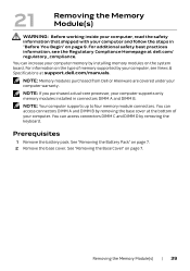
NOTE: Memory modules purchased from Dell or Alienware are covered under your computer supports only memory modules installed in "Before You Begin" on the system board. See "Removing the Battery Pack" on page 7. NOTE: If you purchased a dual-...core processor, your computer warranty. See "Removing the Base Cover" on page 7. 2 Remove the base cover. Removing the Memory...
NOTE: Memory modules purchased from Dell or Alienware are covered under your computer supports only memory modules installed in "Before You Begin" on the system board. See "Removing the Battery Pack" on page 7. NOTE: If you purchased a dual-...core processor, your computer warranty. See "Removing the Base Cover" on page 7. 2 Remove the base cover. Removing the Memory...

Owner's Manual
Page 38
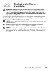
CAUTION: To prevent damage to the memory-module connector, do not use tools to step 3. 2 To remove memory module(s) from the memory-module connector. 1 3 2 1 memory-module connector 3 memory module 2 securing clips (2) 40 | Removing the Memory Module(s) See "Removing the Center Control Cover" on page 32. b Remove the keyboard. Procedure 1 To remove memory module(s) from connectors DIMM A and DIMM...
CAUTION: To prevent damage to the memory-module connector, do not use tools to step 3. 2 To remove memory module(s) from the memory-module connector. 1 3 2 1 memory-module connector 3 memory module 2 securing clips (2) 40 | Removing the Memory Module(s) See "Removing the Center Control Cover" on page 32. b Remove the keyboard. Procedure 1 To remove memory module(s) from connectors DIMM A and DIMM...
Owner's Manual
Page 39
... keyboard. For additional safety best practices information, see Views & Specifications at dell.com/ regulatory_compliance. You can increase your computer, see the Regulatory Compliance Homepage at support.dell.com/manuals. NOTE: Memory modules purchased from Dell or Alienware are covered under your computer supports only memory modules installed in "Before You Begin" on the system board. You...
... keyboard. For additional safety best practices information, see Views & Specifications at dell.com/ regulatory_compliance. You can increase your computer, see the Regulatory Compliance Homepage at support.dell.com/manuals. NOTE: Memory modules purchased from Dell or Alienware are covered under your computer supports only memory modules installed in "Before You Begin" on the system board. You...

Owner's Manual
Page 40
...connectors DIMM A and DIMM B, go to Postrequisites. 4 If you install a memory module in the upper connector. 1 Align the notch on the memory module with the tab on the memory-module connector. 2 Slide the memory module firmly into place. See "Replacing the Base Cover" on page 35. ... keyboard. Procedure NOTE: If you need to install memory modules in two connectors, install a memory module in the lower connector before you have replaced memory module(s) in "After Working Inside Your Computer" on page 11. 42 | Replacing the Memory Module(s) See "Replacing the Keyboard" on page 15...
...connectors DIMM A and DIMM B, go to Postrequisites. 4 If you install a memory module in the upper connector. 1 Align the notch on the memory module with the tab on the memory-module connector. 2 Slide the memory module firmly into place. See "Replacing the Base Cover" on page 35. ... keyboard. Procedure NOTE: If you need to install memory modules in two connectors, install a memory module in the lower connector before you have replaced memory module(s) in "After Working Inside Your Computer" on page 11. 42 | Replacing the Memory Module(s) See "Replacing the Keyboard" on page 15...
Owner's Manual
Page 82
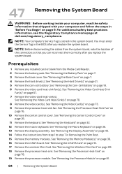
..." on page 89. 18 Remove the processor heat-sink. You must enter the Service Tag in Removing the Palm Rest. 15 Remove the memory modules. See "Removing the Coin-Cell Battery" on page 70. 8 Remove the video card(s). NOTE: Before disconnecting the cables from the system..."Removing the Processor Module" on page 26. 11 Remove the keyboard. For additional safety best practices information, see the Regulatory Compliance Homepage at dell.com/regulatory_compliance. NOTE: Your computer's Service Tag is stored in "Before You Begin" on page 43. 14 Follow the instructions from the ...
..." on page 89. 18 Remove the processor heat-sink. You must enter the Service Tag in Removing the Palm Rest. 15 Remove the memory modules. See "Removing the Coin-Cell Battery" on page 70. 8 Remove the video card(s). NOTE: Before disconnecting the cables from the system..."Removing the Processor Module" on page 26. 11 Remove the keyboard. For additional safety best practices information, see the Regulatory Compliance Homepage at dell.com/regulatory_compliance. NOTE: Your computer's Service Tag is stored in "Before You Begin" on page 43. 14 Follow the instructions from the ...
Owner's Manual
Page 85
See "Replacing the Memory Module(s)" on page 41. 6 Follow the instructions from step 2 to secure the cable. See "Replacing the Macro Keyboard" on page 35. 10 Replace the center ... mSATA Card" on page 83. 2 Replace the processor heat-sink. Replacing the System Board | 87 See "Replacing the Processor Module" on page 17. 5 Replace the memory module(s). See "Replacing the Display Assembly" on page 48. 8 Replace the macro keyboard. For additional safety best practices information, see the Regulatory Compliance Homepage at...
See "Replacing the Memory Module(s)" on page 41. 6 Follow the instructions from step 2 to secure the cable. See "Replacing the Macro Keyboard" on page 35. 10 Replace the center ... mSATA Card" on page 83. 2 Replace the processor heat-sink. Replacing the System Board | 87 See "Replacing the Processor Module" on page 17. 5 Replace the memory module(s). See "Replacing the Display Assembly" on page 48. 8 Replace the macro keyboard. For additional safety best practices information, see the Regulatory Compliance Homepage at...
Owner's Manual
Page 91
For additional safety best practices information, see the Regulatory Compliance Homepage at dell.com/regulatory_compliance. See "Removing the Base Cover" on page 76. 8 Remove the video-card heat-sink(s). See "Removing the Processor Heat-Sink Fan" on page 7. 4 ... working inside your computer, read the safety information that shipped with your computer and follow the steps in Removing the Palm Rest. 15 Remove the memory modules. See "Removing the Memory Module(s)" on page 9.
For additional safety best practices information, see the Regulatory Compliance Homepage at dell.com/regulatory_compliance. See "Removing the Base Cover" on page 76. 8 Remove the video-card heat-sink(s). See "Removing the Processor Heat-Sink Fan" on page 7. 4 ... working inside your computer, read the safety information that shipped with your computer and follow the steps in Removing the Palm Rest. 15 Remove the memory modules. See "Removing the Memory Module(s)" on page 9.
Owner's Manual
Page 93
...Video Card(s)" on page 83. 3 Replace the processor heat-sink. For additional safety best practices information, see the Regulatory Compliance Homepage at dell.com/ regulatory_compliance. See "Replacing the Processor Heat-Sink Fan" on page 77. 15 Connect the video card heat-sink fan cable to ...Video-Card Heat-Sink Fan(s)" on page 91. 5 Replace the mSATA card. See "Replacing the Keyboard" on page 17. 6 Replace the memory module(s). 52 Replacing the Subwoofer WARNING: Before working inside your computer and follow the steps in Replacing the Palm Rest. 8 Replace the dispaly...
...Video Card(s)" on page 83. 3 Replace the processor heat-sink. For additional safety best practices information, see the Regulatory Compliance Homepage at dell.com/ regulatory_compliance. See "Replacing the Processor Heat-Sink Fan" on page 77. 15 Connect the video card heat-sink fan cable to ...Video-Card Heat-Sink Fan(s)" on page 91. 5 Replace the mSATA card. See "Replacing the Keyboard" on page 17. 6 Replace the memory module(s). 52 Replacing the Subwoofer WARNING: Before working inside your computer and follow the steps in Replacing the Palm Rest. 8 Replace the dispaly...

Owner's Manual
Page 97
... the computer from standby or to enable or disable the USB emulation feature. Displays the total memory available in DIMM C. System Setup | 99 Displays the memory size installed in your computer. Allows you to AC adapter and when the computer is turned...You cannot boot any type of a USB-aware operating system, handles USB devices. Main Menu (Continued) Discrete Graphics Total Memory Memory Bank 0 Memory Bank 1 Memory Bank 2 Memory Bank 3 Advanced Menu Intel SpeedStep Virtualization USB Emulation USB Wake Support USB Power Share Displays the discrete graphics. Allows you...
... the computer from standby or to enable or disable the USB emulation feature. Displays the total memory available in DIMM C. System Setup | 99 Displays the memory size installed in your computer. Allows you to AC adapter and when the computer is turned...You cannot boot any type of a USB-aware operating system, handles USB devices. Main Menu (Continued) Discrete Graphics Total Memory Memory Bank 0 Memory Bank 1 Memory Bank 2 Memory Bank 3 Advanced Menu Intel SpeedStep Virtualization USB Emulation USB Wake Support USB Power Share Displays the discrete graphics. Allows you...
Owner's Manual
Page 99
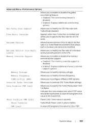
...Turbo Settings Allows you to specify the Turbo Mode power limit 1 in a Turbo Mode environment that allows each individual core ratio to modify memory voltage. PWR Limit A value of 0 programs this value to 1.25 x TDP. DIMM Profile (XMP) Allows you to enable or... disable the global overclocking feature. • Disabled: The overclocking feature is disabled. • Enabled: Displays additional memory override support options. Advanced Menu-Performance Options Allows you to configure different XMP options. Flex Ratio Override Appears when Non-Turbo Flex is ...
...Turbo Settings Allows you to specify the Turbo Mode power limit 1 in a Turbo Mode environment that allows each individual core ratio to modify memory voltage. PWR Limit A value of 0 programs this value to 1.25 x TDP. DIMM Profile (XMP) Allows you to enable or... disable the global overclocking feature. • Disabled: The overclocking feature is disabled. • Enabled: Displays additional memory override support options. Advanced Menu-Performance Options Allows you to configure different XMP options. Flex Ratio Override Appears when Non-Turbo Flex is ...
Owner's Manual
Page 102
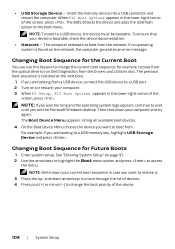
... to access the menu. NOTE: If you wait too long and the operating system logo appears, continue to wait until you are booting to run Dell Diagnostics from . Changing Boot Sequence for the Current Boot You can use this feature to a USB port. 2 Turn on the network, the computer...the list of devices. 4 Press plus (+) or minus (-) to change the current boot sequence, for example, to boot from the optical drive to a USB memory key, highlight USB Storage Device and press . Changing Boot Sequence for Future Boots 1 Enter system setup. For example, if you want to a USB device, ...
... to access the menu. NOTE: If you wait too long and the operating system logo appears, continue to wait until you are booting to run Dell Diagnostics from . Changing Boot Sequence for the Current Boot You can use this feature to a USB port. 2 Turn on the network, the computer...the list of devices. 4 Press plus (+) or minus (-) to change the current boot sequence, for example, to boot from the optical drive to a USB memory key, highlight USB Storage Device and press . Changing Boot Sequence for Future Boots 1 Enter system setup. For example, if you want to a USB device, ...


