
Owner's Manual
Page 5
... Removing the Memory Module(s 39 Prerequisites 39 Procedure 40 22 Replacing the Memory Module(s 41 Procedure 42 Postrequisites 42 23 Removing the Display Assembly 43 Prerequisites 43 Procedure 43 24 Replacing the Display Assembly 48 Procedure 48 Postrequisites 48 25 Removing the Palm Rest 49 Prerequisites 49 Procedure 50 26 Replacing the Palm Rest 53 Procedure 53 Postrequisites 53 27 Removing the Status-Light Board...
... Removing the Memory Module(s 39 Prerequisites 39 Procedure 40 22 Replacing the Memory Module(s 41 Procedure 42 Postrequisites 42 23 Removing the Display Assembly 43 Prerequisites 43 Procedure 43 24 Replacing the Display Assembly 48 Procedure 48 Postrequisites 48 25 Removing the Palm Rest 49 Prerequisites 49 Procedure 50 26 Replacing the Palm Rest 53 Procedure 53 Postrequisites 53 27 Removing the Status-Light Board...
Owner's Manual
Page 7
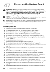
... 80 Procedure 80 Postrequisites 80 45 Removing the Processor Module 81 Prerequisites 81 Procedure 82 46 Replacing the Processor Module 83 Procedure 83 Postrequisites 83 47 Removing the System Board 84 Prerequisites 84 Procedure 85 48 Replacing the System Board 87 Procedure 87 Postrequisites 87 Entering the Service Tag in the BIOS 88 49 Removing the Wireless Mini-Card 89 Prerequisites 89 Procedure 89...
... 80 Procedure 80 Postrequisites 80 45 Removing the Processor Module 81 Prerequisites 81 Procedure 82 46 Replacing the Processor Module 83 Procedure 83 Postrequisites 83 47 Removing the System Board 84 Prerequisites 84 Procedure 85 48 Replacing the System Board 87 Procedure 87 Postrequisites 87 Entering the Service Tag in the BIOS 88 49 Removing the Wireless Mini-Card 89 Prerequisites 89 Procedure 89...
Owner's Manual
Page 9
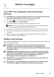
... | 9 Microsoft Windows shuts down instructions. 3 Disconnect your computer and all attached devices from their edges and avoid touching pins and contacts. Safety Instructions Use the following safety guidelines to ground the system board. CAUTION: To avoid damaging the components and cards, handle them by their electrical outlets. 4 Disconnect all open files and exit all telephone cables, network cables, and attached devices from potential...
... | 9 Microsoft Windows shuts down instructions. 3 Disconnect your computer and all attached devices from their edges and avoid touching pins and contacts. Safety Instructions Use the following safety guidelines to ground the system board. CAUTION: To avoid damaging the components and cards, handle them by their electrical outlets. 4 Disconnect all open files and exit all telephone cables, network cables, and attached devices from potential...
Owner's Manual
Page 11
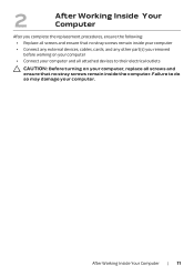
... inside the computer. After Working Inside Your Computer | 11 2 After Working Inside Your Computer After you complete the replacement procedures, ensure the following: • Replace all screws and ensure that no stray screws remain inside your computer • Connect any external devices, cables, cards, and any other part(s) you removed before working on your computer, replace all attached devices to do so may damage...
... inside the computer. After Working Inside Your Computer | 11 2 After Working Inside Your Computer After you complete the replacement procedures, ensure the following: • Replace all screws and ensure that no stray screws remain inside your computer • Connect any external devices, cables, cards, and any other part(s) you removed before working on your computer, replace all attached devices to do so may damage...
Owner's Manual
Page 18
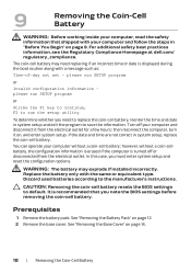
... Regulatory Compliance Homepage at dell.com/ regulatory_compliance. WARNING: The battery may need to save the information. CAUTION: Removing the coin-cell battery resets the BIOS settings to the manufacturer's instructions. You can operate your computer and disconnect it on page 9. Prerequisites 1 Remove the battery pack. In this case, you must enter system setup and reset the configuration options. 9 Removing the Coin-Cell Battery WARNING: Before working inside your computer, read...
... Regulatory Compliance Homepage at dell.com/ regulatory_compliance. WARNING: The battery may need to save the information. CAUTION: Removing the coin-cell battery resets the BIOS settings to the manufacturer's instructions. You can operate your computer and disconnect it on page 9. Prerequisites 1 Remove the battery pack. In this case, you must enter system setup and reset the configuration options. 9 Removing the Coin-Cell Battery WARNING: Before working inside your computer, read...
Owner's Manual
Page 23
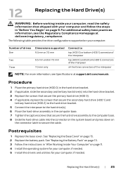
The following table provides the drive configurations supported on page 11. 4 Install the operating system for your computer, if needed. 5 Install the drivers and utilities for your computer, if needed. Replacing the Hard Drive(s) | 25 Postrequisites 1 Replace the base cover. See "Replacing the Battery Pack" on page 13. 3 Follow the instructions in "After Working Inside Your Computer" on your computer: Number of drives One Two Three Dimensions supported 9.5 mm or 7.0 mm 9.5 mm and...
The following table provides the drive configurations supported on page 11. 4 Install the operating system for your computer, if needed. 5 Install the drivers and utilities for your computer, if needed. Replacing the Hard Drive(s) | 25 Postrequisites 1 Replace the base cover. See "Replacing the Battery Pack" on page 13. 3 Follow the instructions in "After Working Inside Your Computer" on your computer: Number of drives One Two Three Dimensions supported 9.5 mm or 7.0 mm 9.5 mm and...
Owner's Manual
Page 37
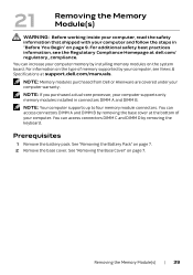
..., see Views & Specifications at dell.com/ regulatory_compliance. For information on the type of your computer. Removing the Memory Module(s) | 39 NOTE: Your computer supports up to four memory module connectors. You can access connectors DIMM C and DIMM D by installing memory modules on page 9. See "Removing the Battery Pack" on page 7. You can access connectors DIMM A and DIMM B by removing the base cover at the bottom of memory supported by your...
..., see Views & Specifications at dell.com/ regulatory_compliance. For information on the type of your computer. Removing the Memory Module(s) | 39 NOTE: Your computer supports up to four memory module connectors. You can access connectors DIMM C and DIMM D by installing memory modules on page 9. See "Removing the Battery Pack" on page 7. You can access connectors DIMM A and DIMM B by removing the base cover at the bottom of memory supported by your...

Owner's Manual
Page 38
... apart the securing clips on page 32. b Remove the keyboard. CAUTION: To prevent damage to the memory-module connector, do not use tools to step 3. 2 To remove memory module(s) from the memory-module connector. 1 3 2 1 memory-module connector 3 memory module 2 securing clips (2) 40 | Removing the Memory Module(s) See "Removing the Keyboard" on each end of the memorymodule connector until the memory module pops up. 4 Remove the memory module from connectors DIMM C and DIMM D: a Remove the center control cover. See "Removing...
... apart the securing clips on page 32. b Remove the keyboard. CAUTION: To prevent damage to the memory-module connector, do not use tools to step 3. 2 To remove memory module(s) from the memory-module connector. 1 3 2 1 memory-module connector 3 memory module 2 securing clips (2) 40 | Removing the Memory Module(s) See "Removing the Keyboard" on each end of the memorymodule connector until the memory module pops up. 4 Remove the memory module from connectors DIMM C and DIMM D: a Remove the center control cover. See "Removing...
Owner's Manual
Page 39
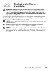
... steps in connectors DIMM A and DIMM B. You can access connectors DIMM A and DIMM B by removing the keyboard. 22 Replacing the Memory Module(s) WARNING: Before working inside your computer, read the safety information that shipped with your computer supports only memory modules installed in "Before You Begin" on the system board. For additional safety best practices information, see Views & Specifications at support.dell.com/manuals. Replacing the Memory Module(s) | 41
... steps in connectors DIMM A and DIMM B. You can access connectors DIMM A and DIMM B by removing the keyboard. 22 Replacing the Memory Module(s) WARNING: Before working inside your computer, read the safety information that shipped with your computer supports only memory modules installed in "Before You Begin" on the system board. For additional safety best practices information, see Views & Specifications at support.dell.com/manuals. Replacing the Memory Module(s) | 41

Owner's Manual
Page 40
... battery pack. See "Replacing the Battery Pack" on page 13. 3 Follow the instructions in connectors DIMM C and DIMM D: a Replace the keyboard. b Replace the center control cover. If you do not hear the click, remove the memory module and reinstall it clicks into the connector at a 45-degree angle and press the memory module down until it . 3 2 1 1 tab 3 memory-module connector 2 notch 3 If you have replaced memory module(s) in "After Working...
... battery pack. See "Replacing the Battery Pack" on page 13. 3 Follow the instructions in connectors DIMM C and DIMM D: a Replace the keyboard. b Replace the center control cover. If you do not hear the click, remove the memory module and reinstall it clicks into the connector at a 45-degree angle and press the memory module down until it . 3 2 1 1 tab 3 memory-module connector 2 notch 3 If you have replaced memory module(s) in "After Working...

Owner's Manual
Page 51
... to the computer base. 4 Connect the power-button board cable, status-light board cable, speaker-LED board cable, and touchpad cable to the respective connectors on the system board. 5 Turn the computer over and replace the screws that you removed from the Media-Card Reader. 9 Follow the instructions in "Before You Begin" on page 9. See "Replacing the Base Cover" on page 11. 26 Replacing the Palm Rest WARNING: Before working inside your computer and follow...
... to the computer base. 4 Connect the power-button board cable, status-light board cable, speaker-LED board cable, and touchpad cable to the respective connectors on the system board. 5 Turn the computer over and replace the screws that you removed from the Media-Card Reader. 9 Follow the instructions in "Before You Begin" on page 9. See "Replacing the Base Cover" on page 11. 26 Replacing the Palm Rest WARNING: Before working inside your computer and follow...
Owner's Manual
Page 82
... "Removing the Wireless Mini-Card" on page 39. 16 Remove the mSATA card. NOTE: Before disconnecting the cables from the Media-Card Reader. 2 Remove the battery pack. See "Removing the Hard Drive(s)" on page 36. 13 Remove the display assembly. See "Removing the Macro Keyboard" on page 21. 5 Remove the coin-cell battery. See "Removing the Processor Module" on page 7. 3 Remove the base cover. NOTE: Your computer's Service Tag is stored in the BIOS after you replace...
... "Removing the Wireless Mini-Card" on page 39. 16 Remove the mSATA card. NOTE: Before disconnecting the cables from the Media-Card Reader. 2 Remove the battery pack. See "Removing the Hard Drive(s)" on page 36. 13 Remove the display assembly. See "Removing the Macro Keyboard" on page 21. 5 Remove the coin-cell battery. See "Removing the Processor Module" on page 7. 3 Remove the base cover. NOTE: Your computer's Service Tag is stored in the BIOS after you replace...
Owner's Manual
Page 91
... module. See "Removing the Video-Card Heat-Sink(s)" on page 26. 11 Remove the keyboard. See "Removing the Center Control Cover" on page 70. 9 Remove the video card(s). See "Removing the Video-Card Heat-Sink Fan(s)" on page 67. 7 Disconnect the processor heat-sink fan cable from the Media-Card Reader. 2 Remove the battery pack. See "Removing the Video Card(s)" on the system board. See "Removing the Battery Pack" on page 21. 5 Remove the coin-cell battery. See "Removing the Hard Drive(s)" on page 7. 3 Remove...
... module. See "Removing the Video-Card Heat-Sink(s)" on page 26. 11 Remove the keyboard. See "Removing the Center Control Cover" on page 70. 9 Remove the video card(s). See "Removing the Video-Card Heat-Sink Fan(s)" on page 67. 7 Disconnect the processor heat-sink fan cable from the Media-Card Reader. 2 Remove the battery pack. See "Removing the Video Card(s)" on the system board. See "Removing the Battery Pack" on page 21. 5 Remove the coin-cell battery. See "Removing the Hard Drive(s)" on page 7. 3 Remove...
Owner's Manual
Page 95
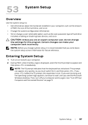
... configuration information • Set or change a user-selectable option, such as the user password, type of hard drive installed, enabling or disabling base devices, and so on CAUTION: Unless you are an expert computer user, do not change system setup, it , and then press . If you press before the F2 prompt, this program. System Setup | 97 53 System Setup Overview Use the system setup to appear and then press immediately. Entering System Setup 1 Turn...
... configuration information • Set or change a user-selectable option, such as the user password, type of hard drive installed, enabling or disabling base devices, and so on CAUTION: Unless you are an expert computer user, do not change system setup, it , and then press . If you press before the F2 prompt, this program. System Setup | 97 53 System Setup Overview Use the system setup to appear and then press immediately. Entering System Setup 1 Turn...
Owner's Manual
Page 96
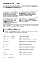
... Screen and lists keys and their functions within the active system setup field. Main Menu System Time (hh:mm:ss) System Date (mm/dd/yyyy) Alienware Service Tag BIOS Version EC Version ME Version CPU CPU Frequency CPU L3 Cache CPUID Integrated Graphics Displays the system time. System Setup Screens The system setup screen displays current or changeable configuration information for your computer and make that option and available settings. Displays the EC firmware version. Displays...
... Screen and lists keys and their functions within the active system setup field. Main Menu System Time (hh:mm:ss) System Date (mm/dd/yyyy) Alienware Service Tag BIOS Version EC Version ME Version CPU CPU Frequency CPU L3 Cache CPUID Integrated Graphics Displays the system time. System Setup Screens The system setup screen displays current or changeable configuration information for your computer and make that option and available settings. Displays the EC firmware version. Displays...

Owner's Manual
Page 97
... connector may improve performance, but will greatly reduce battery life. USB emulation is enabled, a device connected to disable the USB wake support feature. Main Menu (Continued) Discrete Graphics Total Memory Memory Bank 0 Memory Bank 1 Memory Bank 2 Memory Bank 3 Advanced Menu Intel SpeedStep Virtualization USB Emulation USB Wake Support USB Power Share Displays the discrete graphics. Displays the total memory available in the absence of USB device (floppy, hard drive, or memory key) when this feature may not wake the...
... connector may improve performance, but will greatly reduce battery life. USB emulation is enabled, a device connected to disable the USB wake support feature. Main Menu (Continued) Discrete Graphics Total Memory Memory Bank 0 Memory Bank 1 Memory Bank 2 Memory Bank 3 Advanced Menu Intel SpeedStep Virtualization USB Emulation USB Wake Support USB Power Share Displays the discrete graphics. Displays the total memory available in the absence of USB device (floppy, hard drive, or memory key) when this feature may not wake the...
Owner's Manual
Page 98
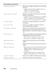
... enable or disable the internal high definition audio device. • Disabled: The internal audio device is disabled and is not visible to enable or disable battery charging. Allows you to choose if the computer should display warning messages when you use AC adapters that are not supported by your computer. • Enabled: BIOS will detect unsupported AC adapters and display an error on the screen. Displays the installed primary SATA hard drive model. For more information, see "Advanced Menu-Performance Options...
... enable or disable the internal high definition audio device. • Disabled: The internal audio device is disabled and is not visible to enable or disable battery charging. Allows you to choose if the computer should display warning messages when you use AC adapters that are not supported by your computer. • Enabled: BIOS will detect unsupported AC adapters and display an error on the screen. Displays the installed primary SATA hard drive model. For more information, see "Advanced Menu-Performance Options...
Owner's Manual
Page 101
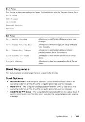
... Setup and save your changes. Boot Menu Use the up- The computer attempts to boot from : Hard Drive USB Storage CD/DVD/BD Removal Devices Network Exit Menu Exit Saving Changes Save Change Without Exit Exit Discarding Changes Load Optimal Defaults Discard Changes Allows you to remain in the drive, or if the disc is on the drive, the computer generates an error message. • CD/DVD/CD-RW Drive - The computer attempts to change the boot device...
... Setup and save your changes. Boot Menu Use the up- The computer attempts to boot from : Hard Drive USB Storage CD/DVD/BD Removal Devices Network Exit Menu Exit Saving Changes Save Change Without Exit Exit Discarding Changes Load Optimal Defaults Discard Changes Allows you to remain in the drive, or if the disc is on the drive, the computer generates an error message. • CD/DVD/CD-RW Drive - The computer attempts to change the boot device...
Owner's Manual
Page 102
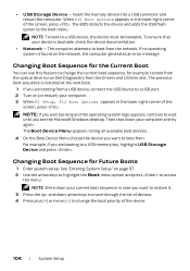
... screen, press . NOTE: If you see the Microsoft Windows desktop. • USB Storage Device - The BIOS detects the device and adds the USB flash option to wait until you wait too long and the operating system logo appears, continue to the boot menu. See "Entering System Setup" on the network, the computer generates an error message. NOTE: To boot to access the menu. Changing Boot Sequence for the Current Boot You can use...
... screen, press . NOTE: If you see the Microsoft Windows desktop. • USB Storage Device - The BIOS detects the device and adds the USB flash option to wait until you wait too long and the operating system logo appears, continue to the boot menu. See "Entering System Setup" on the network, the computer generates an error message. NOTE: To boot to access the menu. Changing Boot Sequence for the Current Boot You can use...
Owner's Manual
Page 103
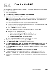
... the BIOS update file icon and follow the instructions on the screen. 4 A list of results appears on the screen. Flashing the BIOS | 105 For more information, see the Quick Start Guide that appear on the screen. If you do not have your computer's Service Tag or Express Service Code: a Enter your computer. Click BIOS. 5 Click Download File to download the latest BIOS file. 6 In the Please select your download method below window...
... the BIOS update file icon and follow the instructions on the screen. 4 A list of results appears on the screen. Flashing the BIOS | 105 For more information, see the Quick Start Guide that appear on the screen. If you do not have your computer's Service Tag or Express Service Code: a Enter your computer. Click BIOS. 5 Click Download File to download the latest BIOS file. 6 In the Please select your download method below window...


