
MOBILE MANUAL
Page 42
... information, see "Function Keys" on the function keys. As Alienware releases new programs, they download directly into the Command Center allowing you access to Alienware's exclusive software and is a continuously upgradable control panel. Connecting a Display Use the appropriate cable based on the connectors available on your computer and display. Refer to the following table to identify the connectors on your computer and display. Connecting External Displays If you can access Alienware Command Center by...
... information, see "Function Keys" on the function keys. As Alienware releases new programs, they download directly into the Command Center allowing you access to Alienware's exclusive software and is a continuously upgradable control panel. Connecting a Display Use the appropriate cable based on the connectors available on your computer and display. Refer to the following table to identify the connectors on your computer and display. Connecting External Displays If you can access Alienware Command Center by...
MOBILE MANUAL
Page 57
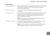
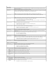
... battery life. USB emulation is enabled, a device connected to enable or disable the Intel SpeedStep technology. NOTE: If USB Powershare is always enabled during POST. Allows you to disable the USB wake support feature. This feature defines how the BIOS, in the absence of USB device (hard drive, or memory key) when this feature may not wake the computer. 55 Disabling this option is off. NOTE: You cannot boot any type of a USB-aware operating...
... battery life. USB emulation is enabled, a device connected to enable or disable the Intel SpeedStep technology. NOTE: If USB Powershare is always enabled during POST. Allows you to disable the USB wake support feature. This feature defines how the BIOS, in the absence of USB device (hard drive, or memory key) when this feature may not wake the computer. 55 Disabling this option is off. NOTE: You cannot boot any type of a USB-aware operating...

MOBILE MANUAL
Page 77
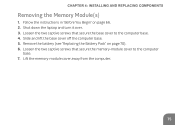
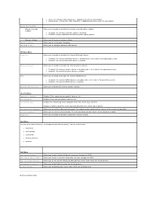
Lift the memory-module cover away from the computer. 75 Remove the battery (see "Replacing the Battery Pack" on page 66. 2. Slide and lift the base cover off the computer base. 5. Follow the instructions in "Before You Begin" on page 70). 6. Loosen the two captive screws that secure the memory-module cover to the computer base. 4. Shut down the laptop and turn it over. 3. CHAPTER 4: INSTALLING AND REPLACING COMPONENTS Removing the Memory Module(s) 1. Loosen the two captive screws that secure the base cover to the computer base. 7.
Lift the memory-module cover away from the computer. 75 Remove the battery (see "Replacing the Battery Pack" on page 66. 2. Slide and lift the base cover off the computer base. 5. Follow the instructions in "Before You Begin" on page 70). 6. Loosen the two captive screws that secure the memory-module cover to the computer base. 4. Shut down the laptop and turn it over. 3. CHAPTER 4: INSTALLING AND REPLACING COMPONENTS Removing the Memory Module(s) 1. Loosen the two captive screws that secure the base cover to the computer base. 7.

MOBILE MANUAL
Page 42
... connectors available on the function keys. NOTE: When connecting to a single display, connect the display to Alienware's exclusive software and is a continuously upgradable control panel. You can connect an external display such as a standalone monitor, an LCD TV, or a projector. For more information, see "Function Keys" on your computer and display. CHAPTER 3: USING YOUR LAPTOP Alienware Command Center The Alienware Command Center gives you access to ONLY ONE of system management, optimization, and customization tools...
... connectors available on the function keys. NOTE: When connecting to a single display, connect the display to Alienware's exclusive software and is a continuously upgradable control panel. You can connect an external display such as a standalone monitor, an LCD TV, or a projector. For more information, see "Function Keys" on your computer and display. CHAPTER 3: USING YOUR LAPTOP Alienware Command Center The Alienware Command Center gives you access to ONLY ONE of system management, optimization, and customization tools...

MOBILE MANUAL
Page 57
Disabling this option is always enabled during POST. NOTE: If USB Powershare is enabled, a device connected to enable or disable the Intel SpeedStep technology. CHAPTER 3: USING YOUR LAPTOP Advanced Menu Intel SpeedStep Virtualization USB Emulation USB Wake Support Allows you to the USB Powershare connector may improve performance, but will greatly reduce battery life. This feature defines how the BIOS, in the absence of USB device (hard drive, or memory key) when this feature may...
Disabling this option is always enabled during POST. NOTE: If USB Powershare is enabled, a device connected to enable or disable the Intel SpeedStep technology. CHAPTER 3: USING YOUR LAPTOP Advanced Menu Intel SpeedStep Virtualization USB Emulation USB Wake Support Allows you to the USB Powershare connector may improve performance, but will greatly reduce battery life. This feature defines how the BIOS, in the absence of USB device (hard drive, or memory key) when this feature may...
MOBILE MANUAL
Page 77
Slide and lift the base cover off the computer base. 5. Lift the memory-module cover away from the computer. 75 Loosen the two captive screws that secure the memory-module cover to the computer base. 4. Loosen the two captive screws that secure the base cover to the computer base. 7. Remove the battery (see "Replacing the Battery Pack" on page 66. 2. CHAPTER 4: INSTALLING AND REPLACING COMPONENTS Removing the Memory Module(s) 1. Follow the instructions in "Before You Begin" on page 70). 6. Shut down the laptop and turn it over. 3.
Slide and lift the base cover off the computer base. 5. Lift the memory-module cover away from the computer. 75 Loosen the two captive screws that secure the memory-module cover to the computer base. 4. Loosen the two captive screws that secure the base cover to the computer base. 7. Remove the battery (see "Replacing the Battery Pack" on page 66. 2. CHAPTER 4: INSTALLING AND REPLACING COMPONENTS Removing the Memory Module(s) 1. Follow the instructions in "Before You Begin" on page 70). 6. Shut down the laptop and turn it over. 3.
Service Manual
Page 1
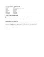
... type: P18G001 2011 - 02 Rev. Alienware® M14x Service Manual Before You Begin Base Cover Battery Pack Optical Drive Hard Drive Memory Module(s) Center-Control Cover Keyboard Palm-Rest Assembly Wireless Mini-Card(s) Power-Button Board Status-Light Board Speakers Subwoofer Internal Card With Bluetooth® Wireless Technology Coin-Cell Battery Display Assembly Mini-Card Board System Board Thermal Fan Thermal Cooling Assembly Processor Module System Setup Flashing the BIOS Notes, Cautions, and Warnings NOTE: A NOTE indicates important information that helps you make better use of Dell...
... type: P18G001 2011 - 02 Rev. Alienware® M14x Service Manual Before You Begin Base Cover Battery Pack Optical Drive Hard Drive Memory Module(s) Center-Control Cover Keyboard Palm-Rest Assembly Wireless Mini-Card(s) Power-Button Board Status-Light Board Speakers Subwoofer Internal Card With Bluetooth® Wireless Technology Coin-Cell Battery Display Assembly Mini-Card Board System Board Thermal Fan Thermal Cooling Assembly Processor Module System Setup Flashing the BIOS Notes, Cautions, and Warnings NOTE: A NOTE indicates important information that helps you make better use of Dell...

Service Manual
Page 6
... set the type of your computer and installed devices, the items listed in your laptop. Displays the memory size installed in DIMM 1. If an error occurs during Power On Self Test (POST), you add, change a user-selectable option. Displays the EC firmware version. Back to Contents Page System Setup Alienware® M14x Service Manual Configuring the System Setup Configuring the System Setup The System Setup options allow you to wait until the System Setup screen appears. 2. l Set or change or remove any hardware...
... set the type of your computer and installed devices, the items listed in your laptop. Displays the memory size installed in DIMM 1. If an error occurs during Power On Self Test (POST), you add, change a user-selectable option. Displays the EC firmware version. Back to Contents Page System Setup Alienware® M14x Service Manual Configuring the System Setup Configuring the System Setup The System Setup options allow you to wait until the System Setup screen appears. 2. l Set or change or remove any hardware...
Service Manual
Page 7
... Power Limit Short Duration Time Window Allows you to enable or disable the internal high definition audio device. USB Power Share Integrated Network High Definition Audio SD Card Reader Performance Options SATA Operation SATA HARD DRIVE 1 Adapter Warnings Charger Behavior NOTE: If USB Powershare is enabled, a device connected to the USB Powershare connector may improve performance, but will not display any type of a USB-aware operating system, handles USB devices. Allows you to override CPU turbo mode settings. Allows you to enable or disable...
... Power Limit Short Duration Time Window Allows you to enable or disable the internal high definition audio device. USB Power Share Integrated Network High Definition Audio SD Card Reader Performance Options SATA Operation SATA HARD DRIVE 1 Adapter Warnings Charger Behavior NOTE: If USB Powershare is enabled, a device connected to the USB Powershare connector may improve performance, but will not display any type of a USB-aware operating system, handles USB devices. Allows you to override CPU turbo mode settings. Allows you to enable or disable...
Service Manual
Page 8
.... Boot Menu Use the up or down arrow keys to set the user password. l Disabled: The memory override support is enabled. l Disabled: The internal Bluetooth device is disabled and is clear or set . l Enabled: The internal Bluetooth device is present. Allows you to change the boot device priority. Displays the service tag of the computer when the service tag is enabled. Allows you to configure different XMP options. l Enabled: The internal wireless device is applied once until the next reboot. Wireless Menu Bluetooth Wireless Network WWAN Wireless Switch/Hotkey...
.... Boot Menu Use the up or down arrow keys to set the user password. l Disabled: The memory override support is enabled. l Disabled: The internal Bluetooth device is disabled and is clear or set . l Enabled: The internal Bluetooth device is present. Allows you to change the boot device priority. Displays the service tag of the computer when the service tag is enabled. Allows you to configure different XMP options. l Enabled: The internal wireless device is applied once until the next reboot. Wireless Menu Bluetooth Wireless Network WWAN Wireless Switch/Hotkey...

Service Manual
Page 9
Back to Contents Page Base Cover Alienware® M14x Service Manual Removing the Base Cover Replacing the Base Cover WARNING: Before working inside your computer, read the safety information that shipped with the slots on your computer. Follow the instructions in Before You Begin. 2. Damage due to the computer base. Follow the instructions in Before You Begin. 2. For additional safety best practices information, see...
Back to Contents Page Base Cover Alienware® M14x Service Manual Removing the Base Cover Replacing the Base Cover WARNING: Before working inside your computer, read the safety information that shipped with the slots on your computer. Follow the instructions in Before You Begin. 2. Damage due to the computer base. Follow the instructions in Before You Begin. 2. For additional safety best practices information, see...

Service Manual
Page 19
... battery (see Turning Off Your Computer) before you connect a cable, ensure that secure the hard-drive assembly to the computer base. 6. CAUTION: To prevent data loss, turn off the computer base. 1 hard-drive interposer 2 captive screws (3) Follow the instructions in Removing the Optical Drive. 5. Some cables have connectors with your computer. Back to Contents Page Hard Drive Alienware® M14x Service Manual Removing the Hard Drive Replacing the Hard Drive WARNING: If you pull connectors apart...
... battery (see Turning Off Your Computer) before you connect a cable, ensure that secure the hard-drive assembly to the computer base. 6. CAUTION: To prevent data loss, turn off the computer base. 1 hard-drive interposer 2 captive screws (3) Follow the instructions in Removing the Optical Drive. 5. Some cables have connectors with your computer. Back to Contents Page Hard Drive Alienware® M14x Service Manual Removing the Hard Drive Replacing the Hard Drive WARNING: If you pull connectors apart...

Service Manual
Page 20
... battery pack (see Replacing the Base Cover). Failure to do so may result in the safety instructions that no stray screws remain inside the computer. Install the operating system for storing or shipping the hard drive. 3. Remove the four screws that secure the hard-drive bracket to the computer. 11. Replacing the Hard Drive 1. Remove the new drive from the hard drive. 1 pull tab 3 hard-drive bracket 2 screws (4) CAUTION: When the hard drive...
... battery pack (see Replacing the Base Cover). Failure to do so may result in the safety instructions that no stray screws remain inside the computer. Install the operating system for storing or shipping the hard drive. 3. Remove the four screws that secure the hard-drive bracket to the computer. 11. Replacing the Hard Drive 1. Remove the new drive from the hard drive. 1 pull tab 3 hard-drive bracket 2 screws (4) CAUTION: When the hard drive...
Service Manual
Page 23
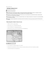
...-Control Cover Alienware® M14x Service Manual Removing the Center-Control Cover Replacing the Center-Control Cover WARNING: Before working inside your computer, read the safety information that is not authorized by Dell is not covered by periodically touching an unpainted metal surface (such as possible. 6. CAUTION: To help prevent damage to the system board, remove the main battery (see the Regulatory Compliance Homepage at dell.com/regulatory_compliance. Remove the base cover...
...-Control Cover Alienware® M14x Service Manual Removing the Center-Control Cover Replacing the Center-Control Cover WARNING: Before working inside your computer, read the safety information that is not authorized by Dell is not covered by periodically touching an unpainted metal surface (such as possible. 6. CAUTION: To help prevent damage to the system board, remove the main battery (see the Regulatory Compliance Homepage at dell.com/regulatory_compliance. Remove the base cover...

Service Manual
Page 31
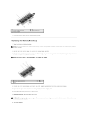
...two user-accessible SODIMM connectors. See "Specifications" in Before You Begin. 2. Removing the Memory Module(s) 1. NOTE: Memory modules purchased from Dell or Alienware are covered under your computer. Remove the base cover (see Removing the Battery Pack). 4. Remove the battery pack (see Removing the Base Cover). 3. Back to the computer base. 5. Loosen the two captive screws that secure the memory-module cover to Contents Page Memory Module(s) Alienware® M14x Service Manual Removing the Memory Module(s) Replacing the Memory Module(s) WARNING: Before working inside...
...two user-accessible SODIMM connectors. See "Specifications" in Before You Begin. 2. Removing the Memory Module(s) 1. NOTE: Memory modules purchased from Dell or Alienware are covered under your computer. Remove the base cover (see Removing the Battery Pack). 4. Remove the battery pack (see Removing the Base Cover). 3. Back to the computer base. 5. Loosen the two captive screws that secure the memory-module cover to Contents Page Memory Module(s) Alienware® M14x Service Manual Removing the Memory Module(s) Replacing the Memory Module(s) WARNING: Before working inside...
Service Manual
Page 32
... you install a memory module in the lower connector before you do so may not boot. 1 memory-module connector 3 notch 2 tab 4. Replace the base cover (see Replacing the Battery Pack). 7. Tighten the two captive screws that no stray screws remain inside the computer. Remove the memory module from the memory-module connector. Replacing the Memory Module(s) 1. 1 memory-module connector 3 memory module 2 securing clips (2) 7. Slide the memory module firmly into place. 5. Replace the battery pack (see Replacing the Base Cover).
... you install a memory module in the lower connector before you do so may not boot. 1 memory-module connector 3 notch 2 tab 4. Replace the base cover (see Replacing the Battery Pack). 7. Tighten the two captive screws that no stray screws remain inside the computer. Remove the memory module from the memory-module connector. Replacing the Memory Module(s) 1. 1 memory-module connector 3 memory module 2 securing clips (2) 7. Slide the memory module firmly into place. 5. Replace the battery pack (see Replacing the Base Cover).

Service Manual
Page 35
.... Remove the new Mini-Card from a source other end of the Mini-Card down into the slot on the system board and replace the screw that shipped with gray stripe WLAN (2 antenna cables) Main WLAN (white triangle) white Auxiliary WLAN (black triangle) black 6. Failure to do so may damage the connector. If you use excessive force, you must install the appropriate drivers and utilities. Install...
.... Remove the new Mini-Card from a source other end of the Mini-Card down into the slot on the system board and replace the screw that shipped with gray stripe WLAN (2 antenna cables) Main WLAN (white triangle) white Auxiliary WLAN (black triangle) black 6. Failure to do so may damage the connector. If you use excessive force, you must install the appropriate drivers and utilities. Install...

Service Manual
Page 41
...-socket cam screw CAUTION: To ensure maximum cooling for the processor module, do not touch the heat transfer areas on your computer. Follow the instructions in Removing the System Board. Back to Contents Page Processor Module Alienware® M14x Service Manual Removing the Processor Module Replacing the Processor Module WARNING: Before working inside your computer, read the safety information that shipped with your computer. Damage...
...-socket cam screw CAUTION: To ensure maximum cooling for the processor module, do not touch the heat transfer areas on your computer. Follow the instructions in Removing the System Board. Back to Contents Page Processor Module Alienware® M14x Service Manual Removing the Processor Module Replacing the Processor Module WARNING: Before working inside your computer, read the safety information that shipped with your computer. Damage...

Service Manual
Page 49
... on the system board. 14. CAUTION: Only a certified service technician should perform repairs on your computer). The system board's BIOS chip contains the Service Tag, which is not covered by your computer. Remove the center-control cover (see Removing the Base Cover). 4. Disconnect the touch-screen board cable, Bluetooth card cable, hard-drive cable, coin-cell battery cable, and subwoofer cable from the 9-in Before You Begin. 2. Remove the base cover (see Removing the Center-Control Cover). 10. Removing the System...
... on the system board. 14. CAUTION: Only a certified service technician should perform repairs on your computer). The system board's BIOS chip contains the Service Tag, which is not covered by your computer. Remove the center-control cover (see Removing the Base Cover). 4. Disconnect the touch-screen board cable, Bluetooth card cable, hard-drive cable, coin-cell battery cable, and subwoofer cable from the 9-in Before You Begin. 2. Remove the base cover (see Removing the Center-Control Cover). 10. Removing the System...
Service Manual
Page 50
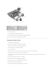
... connectors on the system board with the slots on the computer base and place it on the system board. 10. Replace the center-control cover (see Replacing the Heat Sink). 4. 1 system board 2 screws (5) 3 subwoofer cable connector 4 coin-cell battery cable connector 5 hard-drive cable connector 6 Bluetooth card cable connector 7 touch-screen board cable connector 8 display-cable connector 17. Remove the thermal fan (see Replacing the Processor Module). 3. Replace the processor module (see Removing the Thermal Fan). 19. Connect the display cable to the connector...
... connectors on the system board with the slots on the computer base and place it on the system board. 10. Replace the center-control cover (see Replacing the Heat Sink). 4. 1 system board 2 screws (5) 3 subwoofer cable connector 4 coin-cell battery cable connector 5 hard-drive cable connector 6 Bluetooth card cable connector 7 touch-screen board cable connector 8 display-cable connector 17. Remove the thermal fan (see Replacing the Processor Module). 3. Replace the processor module (see Removing the Thermal Fan). 19. Connect the display cable to the connector...


