
Aurora R6 Liquid Cooling Module
Page 6
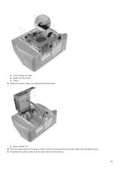
side-panel release latch 3. left -side cover away from the chassis and then lift it from the security-cable slot-if applicable. 1. chassis Installing liquid cooling module NOTE: Ensure that you remove the security cable and security screw from the computer. 1. Slide the power-supply unit cage release latches towards the unlock position. 1. top cover 3. power-supply unit 6 2. Lay the computer on the right side. 4. Release the left -side cover 2. Pull the side-panel release latch. 2.
side-panel release latch 3. left -side cover away from the chassis and then lift it from the security-cable slot-if applicable. 1. chassis Installing liquid cooling module NOTE: Ensure that you remove the security cable and security screw from the computer. 1. Slide the power-supply unit cage release latches towards the unlock position. 1. top cover 3. power-supply unit 6 2. Lay the computer on the right side. 4. Release the left -side cover 2. Pull the side-panel release latch. 2.
Aurora R6 Liquid Cooling Module
Page 7
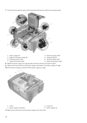
power-supply unit cage 3. Disconnect the processor-fan cable from the chassis. 2. graphics-card bracket 1. chassis 6. Rotate the power-supply unit cage away from the system board. 7 Lift the power-supply unit cage while pressing and holding the graphics-card bracket. 1. power-supply unit 7. 3. power-supply unit cage release cage latches (2) 5.
power-supply unit cage 3. Disconnect the processor-fan cable from the chassis. 2. graphics-card bracket 1. chassis 6. Rotate the power-supply unit cage away from the system board. 7 Lift the power-supply unit cage while pressing and holding the graphics-card bracket. 1. power-supply unit 7. 3. power-supply unit cage release cage latches (2) 5.

Aurora R6 Liquid Cooling Module
Page 9
Stand the computer right side up. 15. chassis 16. top-chassis fan cable 13. screw 4. Lift the right-side cover off the chassis. 2. top-chassis fan 2. Disconnect the lighting cable from the chassis. 1. 1. right-side cover 9 Carefully pry around the edges of the right-side cover from the right-side cover. 17. chassis 3. Rotate the power-supply unit cage towards the chassis until the unit snaps into place. 14.
Stand the computer right side up. 15. chassis 16. top-chassis fan cable 13. screw 4. Lift the right-side cover off the chassis. 2. top-chassis fan 2. Disconnect the lighting cable from the chassis. 1. 1. right-side cover 9 Carefully pry around the edges of the right-side cover from the right-side cover. 17. chassis 3. Rotate the power-supply unit cage towards the chassis until the unit snaps into place. 14.

Aurora R6 Liquid Cooling Module
Page 12
processor-cooling assembly cable 5. Tighten the captive screws that secure the VR heatsink to the system board. 1. Rotate the power-supply unit cage towards the chassis until the unit snaps into place. 12 radiator fan 3. Align the screw holes on the VR heatsink with the screw holes on the system board. 31. system board 2. 1. radiator-fan cable 4. captive screws (4) 32. system board 6. processor-cooling assembly 2. captive screws (4) 30. VR heatsink 3.
processor-cooling assembly cable 5. Tighten the captive screws that secure the VR heatsink to the system board. 1. Rotate the power-supply unit cage towards the chassis until the unit snaps into place. 12 radiator fan 3. Align the screw holes on the VR heatsink with the screw holes on the system board. 31. system board 2. 1. radiator-fan cable 4. captive screws (4) 32. system board 6. processor-cooling assembly 2. captive screws (4) 30. VR heatsink 3.
Aurora R6/R7 U.2 Solid-State Drive Installation Guide
Page 8
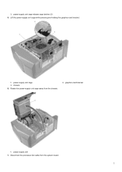
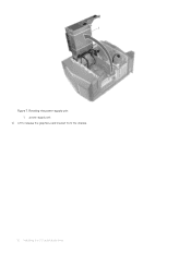
U.2 solid-state drive assembly 1 solid-state drive assembly 2 chassis 9 Slide the power-supply unit cage release latches towards the unlock position. Sliding the power-supply unit cage release latches 1 power-supply unit 3 power-supply unit cage release cage latches (2) 2 chassis 10 Lift the power-supply unit cage while pressing and holding the graphics-card bracket. 8 Installing the U.2 solid-state drive Figure 5. 3 U.2 solid-state drive 8 Slide the U.2 solid-state drive assembly into the hard-drive cage until it snaps into place. Figure 4.
U.2 solid-state drive assembly 1 solid-state drive assembly 2 chassis 9 Slide the power-supply unit cage release latches towards the unlock position. Sliding the power-supply unit cage release latches 1 power-supply unit 3 power-supply unit cage release cage latches (2) 2 chassis 10 Lift the power-supply unit cage while pressing and holding the graphics-card bracket. 8 Installing the U.2 solid-state drive Figure 5. 3 U.2 solid-state drive 8 Slide the U.2 solid-state drive assembly into the hard-drive cage until it snaps into place. Figure 4.
Aurora R6/R7 U.2 Solid-State Drive Installation Guide
Page 9
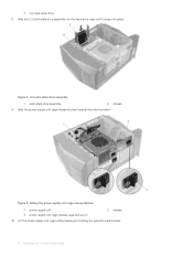
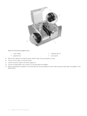
Figure 6. Rotating the power-supply unit 1 power-supply unit cage 3 chassis 11 Rotate the power-supply unit cage away from the chassis. 2 graphics-card bracket Installing the U.2 solid-state drive 9
Figure 6. Rotating the power-supply unit 1 power-supply unit cage 3 chassis 11 Rotate the power-supply unit cage away from the chassis. 2 graphics-card bracket Installing the U.2 solid-state drive 9
Aurora R6/R7 U.2 Solid-State Drive Installation Guide
Page 10
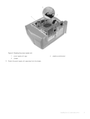
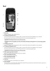
Figure 7. Rotating the power-supply unit 1 power-supply unit 12 Lift to release the graphics-card bracket from the chassis. 10 Installing the U.2 solid-state drive
Figure 7. Rotating the power-supply unit 1 power-supply unit 12 Lift to release the graphics-card bracket from the chassis. 10 Installing the U.2 solid-state drive
Aurora R6/R7 U.2 Solid-State Drive Installation Guide
Page 12
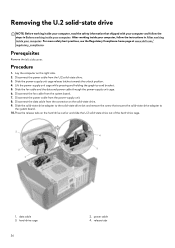
Removing the graphics card 1 power cables 3 graphics card 2 releasing clips (2) 4 securing tab 15 Slide the fan cable and the data and power cable through the power-supply unit cage. 16 Connect the fan cable to the system board. 17 Connect the power cable to the power-supply unit. 18 Connect the data cable to the connector on the solid-state drive adapter. 19 Slide the solid-state drive adapter to the solid-state drive slot and replace the screw that secures the solid-state drive adapter to the system board. 12 Installing the U.2 solid-state drive Figure 9.
Removing the graphics card 1 power cables 3 graphics card 2 releasing clips (2) 4 securing tab 15 Slide the fan cable and the data and power cable through the power-supply unit cage. 16 Connect the fan cable to the system board. 17 Connect the power cable to the power-supply unit. 18 Connect the data cable to the connector on the solid-state drive adapter. 19 Slide the solid-state drive adapter to the solid-state drive slot and replace the screw that secures the solid-state drive adapter to the system board. 12 Installing the U.2 solid-state drive Figure 9.

Aurora R6/R7 U.2 Solid-State Drive Installation Guide
Page 13
Connecting the cables 1 solid-state drive slot 3 data cable 5 power cable 2 screw 4 solid-state drive adapter 6 fan cable 20 Align the graphics card ...into place. 22 Connect the power cables to the graphics card. 23 Slide the tab on the graphics-card bracket into the slot on the chassis and snap it into place. 24 Rotate the power-supply unit cage towards the chassis... until the unit snaps into place. 25 Connect the power cable to the U.2 solid-state drive. Figure 10. Installing the U.2 solid...
Connecting the cables 1 solid-state drive slot 3 data cable 5 power cable 2 screw 4 solid-state drive adapter 6 fan cable 20 Align the graphics card ...into place. 22 Connect the power cables to the graphics card. 23 Slide the tab on the graphics-card bracket into the slot on the chassis and snap it into place. 24 Rotate the power-supply unit cage towards the chassis... until the unit snaps into place. 25 Connect the power cable to the U.2 solid-state drive. Figure 10. Installing the U.2 solid...
Aurora R6 Setup and Specifications
Page 9
...-Express X16 (graphics slot 1) is a unique alphanumeric identifier that enables Dell service technicians to check the power‑supply state. 7. Power-supply cage release-latches (2) Allows you have two graphics cards, the card installed in your computer. 6. Power port Connect a power cable to provide power to remove the power supply unit from your computer and access warranty information. 9 PCI-Express...
...-Express X16 (graphics slot 1) is a unique alphanumeric identifier that enables Dell service technicians to check the power‑supply state. 7. Power-supply cage release-latches (2) Allows you have two graphics cards, the card installed in your computer. 6. Power port Connect a power cable to provide power to remove the power supply unit from your computer and access warranty information. 9 PCI-Express...

Aurora R6 Service Manual
Page 4
... Removing the hard-drive cage...40 Procedure...40 Prerequisites...40 21 Replacing the hard-drive cage...41 Procedure...41 Post-requisites...41 22 Removing the power-supply unit...42 Prerequisites...42 Procedure...42 23 Replacing the power-supply unit...46 Procedure...46 Post-requisites...46 4
... Removing the hard-drive cage...40 Procedure...40 Prerequisites...40 21 Replacing the hard-drive cage...41 Procedure...41 Post-requisites...41 22 Removing the power-supply unit...42 Prerequisites...42 Procedure...42 23 Replacing the power-supply unit...46 Procedure...46 Post-requisites...46 4

Aurora R6 Service Manual
Page 10
...Alienware Aurora R6. Screw list The following table provides the list of screws that are used for securing different components to Chassis Screw type #6-32 X 1/4'' Quantity 2 Screw image 2.5-inch hard-drive cage Chassis #6-32 X 1/4'' 4 Power-supply unit hinge Chassis #6-32 X 1/4'' 6 #6-32 X 1/4'' BLK 3 Power-supply unit Power-supply unit bracket Power-supply...-chassis fan bracket Chassis #6-32 X 1/4'' BLK 1 Antenna assembly Chassis #6-32 X 1/4'' 2 Power-button board Rubber foot M.2 SSD card Top cover M3 X 4 2 Bottom cover M3 X 4 4 System board Standoff M2 1 10
...Alienware Aurora R6. Screw list The following table provides the list of screws that are used for securing different components to Chassis Screw type #6-32 X 1/4'' Quantity 2 Screw image 2.5-inch hard-drive cage Chassis #6-32 X 1/4'' 4 Power-supply unit hinge Chassis #6-32 X 1/4'' 6 #6-32 X 1/4'' BLK 3 Power-supply unit Power-supply unit bracket Power-supply...-chassis fan bracket Chassis #6-32 X 1/4'' BLK 1 Antenna assembly Chassis #6-32 X 1/4'' 2 Power-button board Rubber foot M.2 SSD card Top cover M3 X 4 2 Bottom cover M3 X 4 4 System board Standoff M2 1 10

Aurora R6 Service Manual
Page 13
power-supply unit 3. Technical overview NOTE: Before working inside your computer, read the safety information that shipped with your computer and follow the instructions in Before working ... in After working inside your computer. top cover 5. system board 7. graphics card 2. For more safety best practices, see the Regulatory Compliance home page at www.dell.com/ regulatory_compliance. processor fan and heat-sink assembly 8. optical-drive assembly 4. right-side cover 13 Inside view of your computer 1. top-chassis fan 6.
power-supply unit 3. Technical overview NOTE: Before working inside your computer, read the safety information that shipped with your computer and follow the instructions in Before working ... in After working inside your computer. top cover 5. system board 7. graphics card 2. For more safety best practices, see the Regulatory Compliance home page at www.dell.com/ regulatory_compliance. processor fan and heat-sink assembly 8. optical-drive assembly 4. right-side cover 13 Inside view of your computer 1. top-chassis fan 6.
Aurora R6 Service Manual
Page 36
...of the hard-drive cage. 1. Disconnect the power cable from the system board. 7. Slide ... right side. 2. power cable 4. Slide the power-supply unit cage release latches towards the unlock position. 4. Lift the power-supply unit cage while pressing... and holding the graphics-card bracket. 5. hard-drive cage 36 2. After working inside your computer, follow the steps in After working inside your computer. Disconnect the power...the data and power cable through the power-supply unit cage. 6. Disconnect the data cable from the power-supply unit. 8. ...
...of the hard-drive cage. 1. Disconnect the power cable from the system board. 7. Slide ... right side. 2. power cable 4. Slide the power-supply unit cage release latches towards the unlock position. 4. Lift the power-supply unit cage while pressing... and holding the graphics-card bracket. 5. hard-drive cage 36 2. After working inside your computer, follow the steps in After working inside your computer. Disconnect the power...the data and power cable through the power-supply unit cage. 6. Disconnect the data cable from the power-supply unit. 8. ...

Aurora R6 Service Manual
Page 38
hard-drive carrier b. Slide the fan cable and the data and power cable through the power-supply unit cage. 3. For more safety best practices, see the Regulatory Compliance home page at www.dell.com/ regulatory_compliance. Procedure 1. fan cable c. Slide the solid-state drive adapter to the solid-state drive slot ...inside your computer. a. U.2 solid-state drive 2. Connect the fan cable to the system board. 38 Connect the data cable to the power-supply unit. 5. Place the U.2 solid-state drive in the hard-drive carrier and align the tabs on the solid-state drive adapter. 6. Connect the...
hard-drive carrier b. Slide the fan cable and the data and power cable through the power-supply unit cage. 3. For more safety best practices, see the Regulatory Compliance home page at www.dell.com/ regulatory_compliance. Procedure 1. fan cable c. Slide the solid-state drive adapter to the solid-state drive slot ...inside your computer. a. U.2 solid-state drive 2. Connect the fan cable to the system board. 38 Connect the data cable to the power-supply unit. 5. Place the U.2 solid-state drive in the hard-drive carrier and align the tabs on the solid-state drive adapter. 6. Connect the...

Aurora R6 Service Manual
Page 39
solid-state drive adapter 6. power cable Post-requisites Replace the left-side cover. 39 Rotate the power-supply unit cage towards the chassis until the unit snaps into place. 8. power cable 2. Connect the power cable to the U.2 solid-state drive. a. data cable 5. screw 4. fan cable 7. 1. solid-state drive slot 3. chassis b.
solid-state drive adapter 6. power cable Post-requisites Replace the left-side cover. 39 Rotate the power-supply unit cage towards the chassis until the unit snaps into place. 8. power cable 2. Connect the power cable to the U.2 solid-state drive. a. data cable 5. screw 4. fan cable 7. 1. solid-state drive slot 3. chassis b.

Aurora R6 Service Manual
Page 42
Procedure NOTE: Note the routing of all cables as you replace the power supply. 1. a. power-supply unit b. For more safety best practices, see the Regulatory Compliance home page at www.dell.com/ regulatory_compliance. Slide the power-supply unit cage release latches towards the unlock position. chassis c. power-supply unit cage release cage latches (2) 3. After working inside your computer, follow the...
Procedure NOTE: Note the routing of all cables as you replace the power supply. 1. a. power-supply unit b. For more safety best practices, see the Regulatory Compliance home page at www.dell.com/ regulatory_compliance. Slide the power-supply unit cage release latches towards the unlock position. chassis c. power-supply unit cage release cage latches (2) 3. After working inside your computer, follow the...
Aurora R6 Service Manual
Page 43
Rotate the power-supply unit cage away from the graphics card. 6. power-supply unit cage b. chassis 4. Press the releasing clip on the power-cable connectors and disconnect the power cables from the chassis. Disconnect the power cables from the optical drive and hard drives. 43 a. graphics-card bracket c. power-supply unit 5. a.
Rotate the power-supply unit cage away from the graphics card. 6. power-supply unit cage b. chassis 4. Press the releasing clip on the power-cable connectors and disconnect the power cables from the chassis. Disconnect the power cables from the optical drive and hard drives. 43 a. graphics-card bracket c. power-supply unit 5. a.
Aurora R6 Service Manual
Page 44
hard-drive power cable 7. optical-drive power cable 2. Lift the power-supply unit bracket off the power-supply unit cage. 1. chassis 3. power-supply unit bracket 2. releasing clips (2) 6. system-board power cable 8. power-supply unit 3. graphics-card power cables (2) 5. hard-drive power cable 4. Rotate the power-supply unit cage towards the chassis until the unit snaps into place. 9. screws (2) 4. Remove the screws that secure the power-supply unit bracket...
hard-drive power cable 7. optical-drive power cable 2. Lift the power-supply unit bracket off the power-supply unit cage. 1. chassis 3. power-supply unit bracket 2. releasing clips (2) 6. system-board power cable 8. power-supply unit 3. graphics-card power cables (2) 5. hard-drive power cable 4. Rotate the power-supply unit cage towards the chassis until the unit snaps into place. 9. screws (2) 4. Remove the screws that secure the power-supply unit bracket...

Aurora R6 Service Manual
Page 45
chassis b. power-supply unit c. screws (4) 45 a. Lift the power-supply unit, along with the cables, off the chassis. 12.
chassis b. power-supply unit c. screws (4) 45 a. Lift the power-supply unit, along with the cables, off the chassis. 12.


