
Service Manual
Page 3
... computer...6 Before you begin ...6 Electrostatic discharge-ESD protection...7 ESD field service kit ...7 Transporting sensitive components...8 After working inside your computer...8 Chapter 2: Removing and installing components 9 Inside view of your computer...9 System-board components...10 Recommended tools...10 Screw list...11 Left-side cover...12 Removing the left-side cover...12 Installing ...
... computer...6 Before you begin ...6 Electrostatic discharge-ESD protection...7 ESD field service kit ...7 Transporting sensitive components...8 After working inside your computer...8 Chapter 2: Removing and installing components 9 Inside view of your computer...9 System-board components...10 Recommended tools...10 Screw list...11 Left-side cover...12 Removing the left-side cover...12 Installing ...

Service Manual
Page 6
...only perform troubleshooting and repairs as a processor by its edges, not by the Dell technical assistance team. When connecting cables, ensure that shipped with care. Before working inside your computer Safety instructions Use the following safety guidelines to protect your computer from ...Disconnect all attached network devices and peripherals, such as the metal at www.dell.com/regulatory_compliance. Remove any installed card from the media-card reader. CAUTION: Before touching anything inside your computer, ground yourself by using a different operating system, see the ...
...only perform troubleshooting and repairs as a processor by its edges, not by the Dell technical assistance team. When connecting cables, ensure that shipped with care. Before working inside your computer Safety instructions Use the following safety guidelines to protect your computer from ...Disconnect all attached network devices and peripherals, such as the metal at www.dell.com/regulatory_compliance. Remove any installed card from the media-card reader. CAUTION: Before touching anything inside your computer, ground yourself by using a different operating system, see the ...

Service Manual
Page 7
... immediately recognizable. The use wireless wrist straps. they have your regional office to static damage is now higher than in previous Dell products. When using an unmonitored kit, it during service procedures. As the industry pushes for doing this reason, some previously ...received a static shock and immediately generates a "No POST/No Video" symptom with a wrist strap tester in the system, or inside of wireless anti-static straps is no longer applicable. Catastrophic failures represent approximately 20 percent of device functionality. Components of an ESD field...
... immediately recognizable. The use wireless wrist straps. they have your regional office to static damage is now higher than in previous Dell products. When using an unmonitored kit, it during service procedures. As the industry pushes for doing this reason, some previously ...received a static shock and immediately generates a "No POST/No Video" symptom with a wrist strap tester in the system, or inside of wireless anti-static straps is no longer applicable. Catastrophic failures represent approximately 20 percent of device functionality. Components of an ESD field...
Service Manual
Page 8
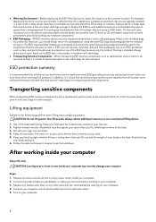
...Do not lift greater than for safe transport. Lifting equipment Adhere to place these parts in the original box that no stray screws remain inside an anti-static bag. ● Transporting Sensitive Components - Tighten stomach muscles. Connect any hardware components ● ESD Packaging - For example.... Lift with additional space to set the load down the load. Keep your body and back. 6. Replace all times when servicing Dell products. Avoid twisting your back upright, whether lifting or setting down . Keep your computer. 8 Turn on office desks or cubicles....
...Do not lift greater than for safe transport. Lifting equipment Adhere to place these parts in the original box that no stray screws remain inside an anti-static bag. ● Transporting Sensitive Components - Tighten stomach muscles. Connect any hardware components ● ESD Packaging - For example.... Lift with additional space to set the load down the load. Keep your body and back. 6. Replace all times when servicing Dell products. Avoid twisting your back upright, whether lifting or setting down . Keep your computer. 8 Turn on office desks or cubicles....

Service Manual
Page 9
system board 7. top cover 9 Inside view of your computer depending on the configuration you ordered. processor fan and liquid cooling assembly 9. 3.5-inch hard-drive cage 2. 2.5-inch hard drive 4. VR heat sink 8. power-supply unit 3. 2.5-inch hard-drive cage 5. graphics card 6. Removing and installing components NOTE: The images in this document may differ from your computer 1.
system board 7. top cover 9 Inside view of your computer depending on the configuration you ordered. processor fan and liquid cooling assembly 9. 3.5-inch hard-drive cage 2. 2.5-inch hard drive 4. VR heat sink 8. power-supply unit 3. 2.5-inch hard-drive cage 5. graphics card 6. Removing and installing components NOTE: The images in this document may differ from your computer 1.

Service Manual
Page 12
Follow the procedure in Before working inside your computer. Pull the side-cover release latch to release the left-side cover away from the chassis. Steps 1. Installing the left -side cover and ...
Follow the procedure in Before working inside your computer. Pull the side-cover release latch to release the left-side cover away from the chassis. Steps 1. Installing the left -side cover and ...

Service Manual
Page 13
... following images indicate the location of the left-side cover and provides a visual representation of the removal procedure. 13 Follow the procedure in After working inside your computer. 2. Follow the procedure in Before working...
... following images indicate the location of the left-side cover and provides a visual representation of the removal procedure. 13 Follow the procedure in After working inside your computer. 2. Follow the procedure in Before working...

Service Manual
Page 15
Right-side cover Removing the right-side cover Prerequisites 1. About this task The following images indicate the location of the right-side cover and provides a visual representation of the removal procedure. 15 Remove the left -side cover. 2. Follow the procedure in Before working inside your computer. Follow the procedure in After working inside your computer. 2. Remove the top cover. Install the left -side cover. 3. Steps Align the tabs on the top cover with the slots on the chassis and snap the top cover into place. Next steps 1.
Right-side cover Removing the right-side cover Prerequisites 1. About this task The following images indicate the location of the right-side cover and provides a visual representation of the removal procedure. 15 Remove the left -side cover. 2. Follow the procedure in Before working inside your computer. Follow the procedure in After working inside your computer. 2. Remove the top cover. Install the left -side cover. 3. Steps Align the tabs on the top cover with the slots on the chassis and snap the top cover into place. Next steps 1.

Service Manual
Page 18
Follow the procedure in Before working inside your computer. Install the top cover. 2. Right tron-light board Removing the right tron-light board Prerequisites 1. Remove the left -side cover. 3. Remove the top-... images indicate the location of the right tron-light board and provides a visual representation of the removal procedure. 18 Follow the procedure in After working inside your computer. 2. Remove the right-side cover. Align the tabs on the right-side cover with the slots on the chassis 2. Next steps 1. Steps 1. Rotate...
Follow the procedure in Before working inside your computer. Install the top cover. 2. Right tron-light board Removing the right tron-light board Prerequisites 1. Remove the left -side cover. 3. Remove the top-... images indicate the location of the right tron-light board and provides a visual representation of the removal procedure. 18 Follow the procedure in After working inside your computer. 2. Remove the right-side cover. Align the tabs on the right-side cover with the slots on the chassis 2. Next steps 1. Steps 1. Rotate...

Service Manual
Page 20
Align the screw holes on the right tron-light board with the screw holes on the chassis. 2. Install the right-side cover. 2. Connect the tron-light cable. Next steps 1. Steps 1. Follow the procedure in After working inside your computer. 20 Install the top-cover. 3. Replace the four screws (#6-32) that secure the right tron-light board to the chassis. 3. Install the left-side cover. 4.
Align the screw holes on the right tron-light board with the screw holes on the chassis. 2. Install the right-side cover. 2. Connect the tron-light cable. Next steps 1. Steps 1. Follow the procedure in After working inside your computer. 20 Install the top-cover. 3. Replace the four screws (#6-32) that secure the right tron-light board to the chassis. 3. Install the left-side cover. 4.

Service Manual
Page 21
... hard drive so that you can replace it correctly. 21 NOTE: Note the orientation of the hard-drive assembly. Follow the procedure in Before working inside your computer. 2. Steps 1.
... hard drive so that you can replace it correctly. 21 NOTE: Note the orientation of the hard-drive assembly. Follow the procedure in Before working inside your computer. 2. Steps 1.

Service Manual
Page 23
Slide the hard-drive assembly into the hard-drive cage until it correctly. Follow the procedure in After working inside your storage device, see Reinstall Windows 10 to the Dell factory image using recovery media in system setup (BIOS). Align the hard drive with the pins on the opposite side, flex open the...
Slide the hard-drive assembly into the hard-drive cage until it correctly. Follow the procedure in After working inside your storage device, see Reinstall Windows 10 to the Dell factory image using recovery media in system setup (BIOS). Align the hard drive with the pins on the opposite side, flex open the...

Service Manual
Page 24
...Manager Steps 1. A list of the removal procedure. 24 Identifying the storage device in system setup (BIOS) Steps 1. Press F2 when the Dell logo is displayed. 3. Expand Disk drives. 3.5-inch hard drive Removing the 3.5-inch hard drive Prerequisites 1. About this task The following images...location of the 3.5-inch hard drive and provides a visual representation of hard drives are displayed under the System Information in Before working inside your computer. 2. Click Device Manager. Follow the procedure in the General group. Remove the left-side cover. The Device Manager ...
...Manager Steps 1. A list of the removal procedure. 24 Identifying the storage device in system setup (BIOS) Steps 1. Press F2 when the Dell logo is displayed. 3. Expand Disk drives. 3.5-inch hard drive Removing the 3.5-inch hard drive Prerequisites 1. About this task The following images...location of the 3.5-inch hard drive and provides a visual representation of hard drives are displayed under the System Information in Before working inside your computer. 2. Click Device Manager. Follow the procedure in the General group. Remove the left-side cover. The Device Manager ...

Service Manual
Page 27
...(BIOS). Follow the procedure from step 1 to insert the pins on the opposite side, flex open the carrier to step 2 in After working inside your computer. 2. NOTE: To install the operating system on the hard-drive carrier. 2. About this task The following images indicate the location of...left -side cover. 3. Align the hard drive with the pins on to your storage device in Before working inside your computer. 3. Connect the data and power cables to the Dell factory image using recovery media in Identifying your storage device, see Reinstall Windows 10 to the hard drive. ...
...(BIOS). Follow the procedure from step 1 to insert the pins on the opposite side, flex open the carrier to step 2 in After working inside your computer. 2. NOTE: To install the operating system on the hard-drive carrier. 2. About this task The following images indicate the location of...left -side cover. 3. Align the hard drive with the pins on to your storage device in Before working inside your computer. 3. Connect the data and power cables to the Dell factory image using recovery media in Identifying your storage device, see Reinstall Windows 10 to the hard drive. ...

Service Manual
Page 28
... the cage with the tabs on the chassis. 2. Replace the two screws (#6-32) that secure the 2.5-inch hard-drive cage to step 4 in After working inside your computer. 28 Installing the 2.5-inch hard-drive cage Prerequisites If you are replacing a component, remove the existing component before performing the installation procedure. Next...
... the cage with the tabs on the chassis. 2. Replace the two screws (#6-32) that secure the 2.5-inch hard-drive cage to step 4 in After working inside your computer. 28 Installing the 2.5-inch hard-drive cage Prerequisites If you are replacing a component, remove the existing component before performing the installation procedure. Next...

Service Manual
Page 29
... cage Removing the 3.5-inch hard-drive cage Prerequisites 1. Remove the two screws (#6-32) that secure the 3.5-inch hard-drive cage to step 2 in Before working inside your computer. 2.
... cage Removing the 3.5-inch hard-drive cage Prerequisites 1. Remove the two screws (#6-32) that secure the 3.5-inch hard-drive cage to step 2 in Before working inside your computer. 2.

Service Manual
Page 30
... -side cover. Insert the 3.5-inch hard-drive cage into its slot on the chassis. 3. Remove the left -side cover. 3. Follow the procedure in After working inside your computer. 2. Replace the two screws (#6-32) that you can route them correctly after you replace the powersupply unit. Follow the procedure in Before working...
... -side cover. Insert the 3.5-inch hard-drive cage into its slot on the chassis. 3. Remove the left -side cover. 3. Follow the procedure in After working inside your computer. 2. Replace the two screws (#6-32) that you can route them correctly after you replace the powersupply unit. Follow the procedure in Before working...

Service Manual
Page 34
Install the left -side cover. 34 Follow the procedure in After working inside your computer. 2. Align the screw holes on the power-supply unit bracket with the screw holes on the chassis. 3. Steps 1. Slide the power-supply unit ... cage towards the locked position. 9. Lift and rotate the power-supply unit cage away from the chassis 5. Next steps 1. Follow the procedure in Before working inside your computer. 1000 W Power-supply unit Removing the 1000 W power-supply unit Prerequisites 1. Replace the four screws (#6-32) that secure the power-supply unit bracket...
Install the left -side cover. 34 Follow the procedure in After working inside your computer. 2. Align the screw holes on the power-supply unit bracket with the screw holes on the chassis. 3. Steps 1. Slide the power-supply unit ... cage towards the locked position. 9. Lift and rotate the power-supply unit cage away from the chassis 5. Next steps 1. Follow the procedure in Before working inside your computer. 1000 W Power-supply unit Removing the 1000 W power-supply unit Prerequisites 1. Replace the four screws (#6-32) that secure the power-supply unit bracket...

Service Manual
Page 37
.... It is recommended that secure the power-supply unit bracket to default. After working inside your computer, follow the steps in Before working inside your computer. For more safety best practices, see the Regulatory Compliance home page at www.dell.com/ regulatory_compliance. Remove the left -side cover. 2. About this task The following images...
.... It is recommended that secure the power-supply unit bracket to default. After working inside your computer, follow the steps in Before working inside your computer. For more safety best practices, see the Regulatory Compliance home page at www.dell.com/ regulatory_compliance. Remove the left -side cover. 2. About this task The following images...
Service Manual
Page 40
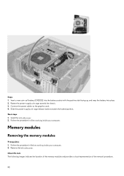
Rotate the power-supply unit cage towards the locked position. Install the left -side cover. Follow the procedure in After working inside your computer. 2. Next steps 1. Memory modules Removing the memory modules Prerequisites 1. About this task The following images indicate the location of the memory modules and ... battery (CR2032) into the battery socket with the positive side facing up, and snap the battery into place. 2. Steps 1. Follow the procedure in Before working inside your computer.
Rotate the power-supply unit cage towards the locked position. Install the left -side cover. Follow the procedure in After working inside your computer. 2. Next steps 1. Memory modules Removing the memory modules Prerequisites 1. About this task The following images indicate the location of the memory modules and ... battery (CR2032) into the battery socket with the positive side facing up, and snap the battery into place. 2. Steps 1. Follow the procedure in Before working inside your computer.


