
Service Manual
Page 3
... Recommended tools...13 Screw list...14 Removing the base cover 16 Procedure...16 Replacing the base cover 17 Procedure...17 Removing the battery...19 Lithium-ion battery precautions...19 Prerequisites...19 Procedure...19 Replacing the battery...21 Procedure ...21 Post-requisites...21 Removing the memory modules 22 Prerequisites...22 Procedure...22 Replacing the memory modules 24 Procedure ...24 Post-requisites...24 Removing the wireless card 25 Prerequisites...25 Procedure...
... Recommended tools...13 Screw list...14 Removing the base cover 16 Procedure...16 Replacing the base cover 17 Procedure...17 Removing the battery...19 Lithium-ion battery precautions...19 Prerequisites...19 Procedure...19 Replacing the battery...21 Procedure ...21 Post-requisites...21 Removing the memory modules 22 Prerequisites...22 Procedure...22 Replacing the memory modules 24 Procedure ...24 Post-requisites...24 Removing the wireless card 25 Prerequisites...25 Procedure...
Service Manual
Page 7
......100 Intel Virtual Button driver...100 Wireless and Bluetooth drivers...100 System setup...101 System setup...101 Entering BIOS setup program...101 Navigation keys...101 Boot Sequence...101 System setup options...102 Clearing CMOS settings...107 Clearing BIOS (System Setup) and System passwords 107 Troubleshooting...108 Flashing the BIOS...108 Flashing BIOS (USB key)...108 Enhanced Pre-Boot System Assessment (ePSA) diagnostics 108 Running the ePSA diagnostics...109 System diagnostic lights...109 Enabling Intel Optane memory...110 Disabling Intel Optane memory...110 WiFi power cycle...111...
......100 Intel Virtual Button driver...100 Wireless and Bluetooth drivers...100 System setup...101 System setup...101 Entering BIOS setup program...101 Navigation keys...101 Boot Sequence...101 System setup options...102 Clearing CMOS settings...107 Clearing BIOS (System Setup) and System passwords 107 Troubleshooting...108 Flashing the BIOS...108 Flashing BIOS (USB key)...108 Enhanced Pre-Boot System Assessment (ePSA) diagnostics 108 Running the ePSA diagnostics...109 System diagnostic lights...109 Enabling Intel Optane memory...110 Disabling Intel Optane memory...110 WiFi power cycle...111...

Service Manual
Page 10
... of device functionality. Intermittent failures represent approximately 80 percent of memory integrity, intermittent memory errors, etc. Touching the chassis before opening the computer cover or panels. Very slight charges can damage circuits in a static-safe area. When connecting cables, ensure that shipped with increased sensitivity to recognize and troubleshoot is no longer applicable. If possible, use of catastrophic failure is an increasing concern. An example of wireless...
... of device functionality. Intermittent failures represent approximately 80 percent of memory integrity, intermittent memory errors, etc. Touching the chassis before opening the computer cover or panels. Very slight charges can damage circuits in a static-safe area. When connecting cables, ensure that shipped with increased sensitivity to recognize and troubleshoot is no longer applicable. If possible, use of catastrophic failure is an increasing concern. An example of wireless...
Service Manual
Page 22
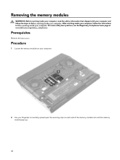
... safety information that shipped with your computer and follow the instructions in Before working inside your fingertips to carefully spread apart the securing-clips on your computer. 2 Use your computer. Prerequisites Remove the base cover. Procedure 1 Locate the memory modules on each end of the memory-module slot until the memory module pops up. 22 After working inside your computer, follow the steps in After...
... safety information that shipped with your computer and follow the instructions in Before working inside your fingertips to carefully spread apart the securing-clips on your computer. 2 Use your computer. Prerequisites Remove the base cover. Procedure 1 Locate the memory modules on each end of the memory-module slot until the memory module pops up. 22 After working inside your computer, follow the steps in After...
Service Manual
Page 24
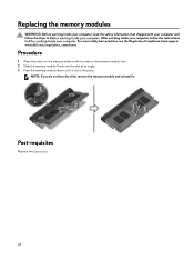
..., remove the memory module and reinstall it clicks into place. Post-requisites Replace the base cover. 24 For more safety best practices, see the Regulatory Compliance home page at an angle. 3 Press the memory module down until it . Procedure 1 Align the notch on the memory-module slot. 2 Slide the memory module firmly into the slot at www.dell.com/regulatory_compliance. Replacing the memory modules WARNING: Before working inside...
..., remove the memory module and reinstall it clicks into place. Post-requisites Replace the base cover. 24 For more safety best practices, see the Regulatory Compliance home page at an angle. 3 Press the memory module down until it . Procedure 1 Align the notch on the memory-module slot. 2 Slide the memory module firmly into the slot at www.dell.com/regulatory_compliance. Replacing the memory modules WARNING: Before working inside...
Service Manual
Page 46
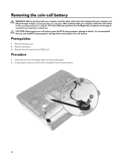
... with your computer and follow the instructions in SSD2 slot). Removing the coin-cell battery WARNING: Before working inside your computer, read the safety information that you note the BIOS setup program's settings before removing the coin-cell battery. CAUTION: Removing the coin-cell battery resets the BIOS setup program's settings to default. Procedure 1 Disconnect the coin-cell battery cable from the system board. 2 Using a plastic scribe, pry off the coin...
... with your computer and follow the instructions in SSD2 slot). Removing the coin-cell battery WARNING: Before working inside your computer, read the safety information that you note the BIOS setup program's settings before removing the coin-cell battery. CAUTION: Removing the coin-cell battery resets the BIOS setup program's settings to default. Procedure 1 Disconnect the coin-cell battery cable from the system board. 2 Using a plastic scribe, pry off the coin...
Service Manual
Page 76
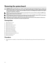
... the instructions in the BIOS setup program after you replace the system board. You must make the appropriate changes again after you replace the system board. NOTE: Before disconnecting the cables from the system board, note the location of the connectors so that shipped with keyboard facing up, disconnect the power-button board cable. 76 Prerequisites 1 Remove the base cover. 2 Remove the battery. 3 Remove the memory modules. 4 Remove the wireless card. 5 Remove the solid-state drive. 6 Remove the rear-I/O cover. 7 Remove the...
... the instructions in the BIOS setup program after you replace the system board. You must make the appropriate changes again after you replace the system board. NOTE: Before disconnecting the cables from the system board, note the location of the connectors so that shipped with keyboard facing up, disconnect the power-button board cable. 76 Prerequisites 1 Remove the base cover. 2 Remove the battery. 3 Remove the memory modules. 4 Remove the wireless card. 5 Remove the solid-state drive. 6 Remove the rear-I/O cover. 7 Remove the...
Service Manual
Page 100
... network card driver is installed. Install the driver updates from www.dell.com/support. In the Device Manager, check if the Bluetooth driver is installed. Intel Serial IO driver In the Device Manager, check if the Intel Serial IO driver is installed. Install the driver updates from www.dell.com/support. 100 Intel Virtual Button driver In the Device Manager, check if the Intel Virtual Button driver is installed. Video drivers In the Device Manager, check if the video driver is installed. Install the driver updates from www.dell.com/support. Install the driver updates from...
... network card driver is installed. Install the driver updates from www.dell.com/support. In the Device Manager, check if the Bluetooth driver is installed. Intel Serial IO driver In the Device Manager, check if the Intel Serial IO driver is installed. Install the driver updates from www.dell.com/support. 100 Intel Virtual Button driver In the Device Manager, check if the Intel Virtual Button driver is installed. Video drivers In the Device Manager, check if the video driver is installed. Install the driver updates from www.dell.com/support. Install the driver updates from...

Service Manual
Page 101
... the hardware installed in your computer and try again. Boot Sequence Boot Sequence allows you to bypass the System Setup-defined boot device order and boot directly to the previous page until you view the main screen. Navigation keys NOTE: For most of the System Setup options, changes that you change a user-selectable option, such as the amount of RAM and the size of hard drive installed, and enabling or disabling base devices. NOTE...
... the hardware installed in your computer and try again. Boot Sequence Boot Sequence allows you to bypass the System Setup-defined boot device order and boot directly to the previous page until you view the main screen. Navigation keys NOTE: For most of the System Setup options, changes that you change a user-selectable option, such as the amount of RAM and the size of hard drive installed, and enabling or disabling base devices. NOTE...
Service Manual
Page 103
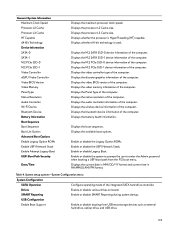
.... Displays the video memory information of the computer. Enable or disable the Legacy Option ROMs. Enable or disable the UEFI Network Stack. Enable or disable the system to prompt the user to enter the Admin password when booting a UEFI boot path from USB mass storage devices such as external hard drive, optical drive, and USB drive. 103 Displays whether the processor is used. Displays the M.2 SATA SSD-1 device information of the computer. Displays the native resolution of the computer. Displays the audio controller...
.... Displays the video memory information of the computer. Enable or disable the Legacy Option ROMs. Enable or disable the UEFI Network Stack. Enable or disable the system to prompt the user to enter the Admin password when booting a UEFI boot path from USB mass storage devices such as external hard drive, optical drive, and USB drive. 103 Displays whether the processor is used. Displays the M.2 SATA SSD-1 device information of the computer. Displays the native resolution of the computer. Displays the audio controller...

Service Manual
Page 104
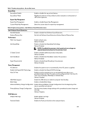
... and Hard Disk passwords when an administrator password is set . Master Password Lockout Disables the master password support. System Configuration Enable External USB Port Enable or disable booting from USB mass storage devices connected to be cleared before changing the setting. Keyboard Backlight Timeout on battery power. Strong Password Enable or disable strong passwords. Password Configuration Control the minimum and maximum number of the keyboard illumination feature. UEFI Capsule Firmware Updates Enable or disable BIOS updates through UEFI capsule update packages...
... and Hard Disk passwords when an administrator password is set . Master Password Lockout Disables the master password support. System Configuration Enable External USB Port Enable or disable booting from USB mass storage devices connected to be cleared before changing the setting. Keyboard Backlight Timeout on battery power. Strong Password Enable or disable strong passwords. Password Configuration Control the minimum and maximum number of the keyboard illumination feature. UEFI Capsule Firmware Updates Enable or disable BIOS updates through UEFI capsule update packages...
Service Manual
Page 105
.... USB Wake Support Enable the USB devices to turn on automatically every day or on the processor load. Enable or disable Intel Speedstep Technology. Default: Enabled. Default: Enabled. Default: Enabled. Block Sleep Enable or disable Block Sleep. Default: Enabled. Numlock Enable Enables the NumLock funcltion when computer boots. 105 System setup options-Secure Boot menu Secure Boot Secure Boot Enable Enable or disable the secure boot feature. Set the Intel Software Guard Extensions Enclave Reserve Memory Size. Intel TurboBoost Enable or disable Intel TurboBoost mode of...
.... USB Wake Support Enable the USB devices to turn on automatically every day or on the processor load. Enable or disable Intel Speedstep Technology. Default: Enabled. Default: Enabled. Default: Enabled. Block Sleep Enable or disable Block Sleep. Default: Enabled. Numlock Enable Enables the NumLock funcltion when computer boots. 105 System setup options-Secure Boot menu Secure Boot Secure Boot Enable Enable or disable the secure boot feature. Set the Intel Software Guard Extensions Enclave Reserve Memory Size. Intel TurboBoost Enable or disable Intel TurboBoost mode of...

Service Manual
Page 106
... Software Guard Extensions Fn Lock Options Fastboot Extend BIOS POST Time Full Screen Logo Warnings and Errors Enable or disable the Fn lock mode. System setup options-Virtualization Support menu Virtualization Support Virtualization Specify whether a Virtual Machine Monitor (VMM) can utilize the additional hardware capabilities provided by Intel Virtualization Technology for SupportAssist OS Recovery tool in the even of the system firmware to recover from certain corrupted BIOS conditions from all internal storage devices...
... Software Guard Extensions Fn Lock Options Fastboot Extend BIOS POST Time Full Screen Logo Warnings and Errors Enable or disable the Fn lock mode. System setup options-Virtualization Support menu Virtualization Support Virtualization Specify whether a Virtual Machine Monitor (VMM) can utilize the additional hardware capabilities provided by Intel Virtualization Technology for SupportAssist OS Recovery tool in the even of the system firmware to recover from certain corrupted BIOS conditions from all internal storage devices...

Service Manual
Page 108
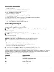
... by the BIOS internally. For more information see Dell EPSA Diagnostic 3.0. 108 Flashing BIOS (USB key) 1 Follow the procedure from the One Time Boot Menu. 7 Type the BIOS setup program filename and press Enter. 8 The BIOS Update Utility appears. Using this program with the BIOS and is displayed on your computer. Follow these steps to flash the BIOS: 1 Turn on the screen. 6 Boot to the computer that you of your computer. 8 After the download is...
... by the BIOS internally. For more information see Dell EPSA Diagnostic 3.0. 108 Flashing BIOS (USB key) 1 Follow the procedure from the One Time Boot Menu. 7 Type the BIOS setup program filename and press Enter. 8 The BIOS Update Utility appears. Using this program with the BIOS and is displayed on your computer. Follow these steps to flash the BIOS: 1 Turn on the screen. 6 Boot to the computer that you of your computer. 8 After the download is...
Service Manual
Page 109
..., error codes are listed. 6 To run a diagnostic test on a specific device, press Esc and click Yes to stop the diagnostic test. 7 Select the device from or writes to the hard drive. NOTE: Press Fn+H to the page listing. The power and battery-status light blinks amber along with hard drive. Diagnostics front page is displayed. 5 Click the arrow in sleep state, hibernation, or turned off indicating no memory or RAM is supported...
..., error codes are listed. 6 To run a diagnostic test on a specific device, press Esc and click Yes to stop the diagnostic test. 7 Select the device from or writes to the hard drive. NOTE: Press Fn+H to the page listing. The power and battery-status light blinks amber along with hard drive. Diagnostics front page is displayed. 5 Click the arrow in sleep state, hibernation, or turned off indicating no memory or RAM is supported...
Setup and Specifications
Page 4
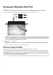
... HDMI cable to connect two adapters. NOTE: Your computer ships with two power adapters, and it is recommended to create a recovery drive to troubleshoot and fix problems that may differ from the VR headset can be connected either to the USB 3.1 Gen 1 Type-A port on your Alienware Graphics Amplifier. For more information, see Alienware Graphics Amplifier User's Guide at www.dell.com/support. 4 Only use adapters supplied with your device. 2. Create recovery drive for Windows. Alienware Graphics Amplifier Alienware Graphics Amplifier enables...
... HDMI cable to connect two adapters. NOTE: Your computer ships with two power adapters, and it is recommended to create a recovery drive to troubleshoot and fix problems that may differ from the VR headset can be connected either to the USB 3.1 Gen 1 Type-A port on your Alienware Graphics Amplifier. For more information, see Alienware Graphics Amplifier User's Guide at www.dell.com/support. 4 Only use adapters supplied with your device. 2. Create recovery drive for Windows. Alienware Graphics Amplifier Alienware Graphics Amplifier enables...

Setup and Specifications
Page 5
... the Microsoft support site for Windows Create a recovery drive to the recovery drive and click Next. 6. Connect the USB flash drive to continue. Select Back up to an hour to create the recovery drive. For more information about reinstalling Windows using the USB recovery drive, see the Troubleshooting section of Windows installed. In the search results, click Create a recovery drive. Select the USB flash drive and click Next. Click Finish. Create a USB recovery drive for latest instructions. 1. In Windows search, type Recovery. 3. A message appears, indicating that may...
... the Microsoft support site for Windows Create a recovery drive to the recovery drive and click Next. 6. Connect the USB flash drive to continue. Select Back up to an hour to create the recovery drive. For more information about reinstalling Windows using the USB recovery drive, see the Troubleshooting section of Windows installed. In the search results, click Create a recovery drive. Select the USB flash drive and click Next. Click Finish. Create a USB recovery drive for latest instructions. 1. In Windows search, type Recovery. 3. A message appears, indicating that may...

Setup and Specifications
Page 6
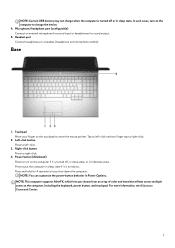
... external display using a display adapter. Right 1. Provides data transfer speeds up to 40 Gbps for Thunderbolt 3. Thunderbolt 3 (USB Type-C) port Supports USB 3.1 Gen 2, DisplayPort 1.2, Thunderbolt 3 and also enables you must connect the power adapter to the PowerShare port. NOTE: A USB Type-C to DisplayPort adapter (sold separately) is less than 10 percent, you to charge your USB devices even when your computer, and USB devices connected to charge your computer is turned off . Left speaker Provides audio output. 2. USB...
... external display using a display adapter. Right 1. Provides data transfer speeds up to 40 Gbps for Thunderbolt 3. Thunderbolt 3 (USB Type-C) port Supports USB 3.1 Gen 2, DisplayPort 1.2, Thunderbolt 3 and also enables you must connect the power adapter to the PowerShare port. NOTE: A USB Type-C to DisplayPort adapter (sold separately) is less than 10 percent, you to charge your USB devices even when your computer, and USB devices connected to charge your computer is turned off . Left speaker Provides audio output. 2. USB...
Setup and Specifications
Page 7
... port Connect headphones or a headset (headphone and microphone combo). Touchpad Move your finger on the computer, including the keyboard, power button, and touchpad. Right-click button Press to put the computer in sleep state. Tap to charge the device. 4. Press to right-click. 4. For more information, see Alienware Command Center. 7 NOTE: Certain USB devices may not charge when the computer is turned off , in sleep state, or in Power Options...
... port Connect headphones or a headset (headphone and microphone combo). Touchpad Move your finger on the computer, including the keyboard, power button, and touchpad. Right-click button Press to put the computer in sleep state. Tap to charge the device. 4. Press to right-click. 4. For more information, see Alienware Command Center. 7 NOTE: Certain USB devices may not charge when the computer is turned off , in sleep state, or in Power Options...
Setup and Specifications
Page 20
.... You can quickly access settings such as profiles, macros, AlienFX, and game library. AWCC embeds Peripheral Controls to ensure a unified experience and the ability to link these settings to the computer or attached peripherals. AWCC also supports Sound Management, Thermal Controls, CPU, GPU, Memory (RAM) monitoring. It also enables you to create, assign, and share game-specific lighting maps to appear in and be managed in Alienware Command Center...
.... You can quickly access settings such as profiles, macros, AlienFX, and game library. AWCC embeds Peripheral Controls to ensure a unified experience and the ability to link these settings to the computer or attached peripherals. AWCC also supports Sound Management, Thermal Controls, CPU, GPU, Memory (RAM) monitoring. It also enables you to create, assign, and share game-specific lighting maps to appear in and be managed in Alienware Command Center...


