Service Manual
Page 3
......9 After working inside your computer 10 Removing the base cover 11 Procedure...11 Replacing the base cover 13 Procedure...13 Removing the wireless card 15 Prerequisites...15 Procedure...15 Replacing the wireless card 17 Procedure...17 Post-requisites...17 Removing the hard drive 18 Prerequisites...18 Procedure...18 Replacing the hard drive 20...
......9 After working inside your computer 10 Removing the base cover 11 Procedure...11 Replacing the base cover 13 Procedure...13 Removing the wireless card 15 Prerequisites...15 Procedure...15 Replacing the wireless card 17 Procedure...17 Post-requisites...17 Removing the hard drive 18 Prerequisites...18 Procedure...18 Replacing the hard drive 20...
Service Manual
Page 9
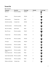
... Keyboard bracket Palm-rest assembly Wireless-card bracket Computer base M2.5x5 M2.5x5 M2x3 M2.5x5 M2x3 M2x3 M2.5x5 M2x3 M2x3 Quantity 6 1 1 3 4 7 2 11 2 2 5 6 1 2 7 15 1 Screw image 9 Screw list Table 1.
... Keyboard bracket Palm-rest assembly Wireless-card bracket Computer base M2.5x5 M2.5x5 M2x3 M2.5x5 M2x3 M2x3 M2.5x5 M2x3 M2x3 Quantity 6 1 1 3 4 7 2 11 2 2 5 6 1 2 7 15 1 Screw image 9 Screw list Table 1.
Service Manual
Page 15
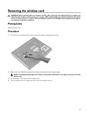
... angle, and slide it from the wireless card. 3 Lift the wireless-card bracket off the wireless card. 4 Lift the wireless card at www.dell.com/regulatory_compliance. Prerequisites Remove the base cover. NOTE: To avoid potential damage to the wireless-card bracket, carefully lift it at an angle and remove... it out of the wireless-card slot. 15 Procedure 1 Lift the flap covering the wireless card to access the wireless-card bracket and screw. 2 Remove the screw (M2x3) that shipped with ...
... angle, and slide it from the wireless card. 3 Lift the wireless-card bracket off the wireless card. 4 Lift the wireless card at www.dell.com/regulatory_compliance. Prerequisites Remove the base cover. NOTE: To avoid potential damage to the wireless-card bracket, carefully lift it at an angle and remove... it out of the wireless-card slot. 15 Procedure 1 Lift the flap covering the wireless card to access the wireless-card bracket and screw. 2 Remove the screw (M2x3) that shipped with ...
Service Manual
Page 47
... cable on the system board. 13 Disconnect the power-adapter port cable from the system board. 14 Disconnect the speaker cable from the system board. 15 Open the latch and disconnect the RGB per key keyboard cable (optional) from the system board. 16 Open the latch and disconnect the touchpad cable...
... cable on the system board. 13 Disconnect the power-adapter port cable from the system board. 14 Disconnect the speaker cable from the system board. 15 Open the latch and disconnect the RGB per key keyboard cable (optional) from the system board. 16 Open the latch and disconnect the touchpad cable...
Service Manual
Page 51
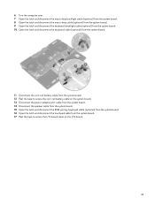
13 Connect the coin-cell battery cable to the system board. 14 Connect the keyboard cable (optional) to the system board. 15 Connect the keyboard-backlight cable (optional) to the system board. 16 Connect the macro-keys cable (optional) to the system board. 17 Connect the macro-...
13 Connect the coin-cell battery cable to the system board. 14 Connect the keyboard cable (optional) to the system board. 15 Connect the keyboard-backlight cable (optional) to the system board. 16 Connect the macro-keys cable (optional) to the system board. 17 Connect the macro-...
Service Manual
Page 53
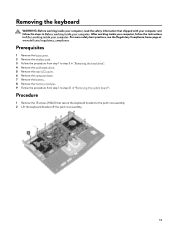
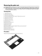
...palm-rest assembly. 53 After working inside your computer, follow the steps in Before working inside your computer. Procedure 1 Remove the 15 screws (M2x3) that shipped with your computer and follow the instructions in After working inside your computer. For more safety best practices..., see the Regulatory Compliance home page at www.dell.com/regulatory_compliance. Removing the keyboard WARNING: Before working inside your computer, read the safety information that secure the keyboard bracket to...
...palm-rest assembly. 53 After working inside your computer, follow the steps in Before working inside your computer. Procedure 1 Remove the 15 screws (M2x3) that shipped with your computer and follow the instructions in After working inside your computer. For more safety best practices..., see the Regulatory Compliance home page at www.dell.com/regulatory_compliance. Removing the keyboard WARNING: Before working inside your computer, read the safety information that secure the keyboard bracket to...
Service Manual
Page 56
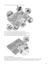
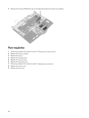
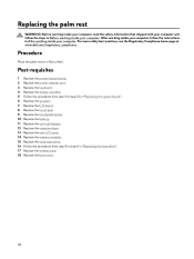
3 Replace the 15 screws (M2x3) that secure the keyboard bracket to step 6 in "Replacing the hard drive". 8 Replace the wireless card. 9 Replace the base cover. 56 Post-requisites 1 Follow the procedure from step 2 to step 16 in "Replacing the system board". 2 Replace the memory modules. 3 Replace the battery. 4 Replace the computer base. 5 Replace the rear-I/O cover. 6 Replace the solid-state drive. 7 Follow the procedure from step 4 to the palm-rest assembly.
3 Replace the 15 screws (M2x3) that secure the keyboard bracket to step 6 in "Replacing the hard drive". 8 Replace the wireless card. 9 Replace the base cover. 56 Post-requisites 1 Follow the procedure from step 2 to step 16 in "Replacing the system board". 2 Replace the memory modules. 3 Replace the battery. 4 Replace the computer base. 5 Replace the rear-I/O cover. 6 Replace the solid-state drive. 7 Follow the procedure from step 4 to the palm-rest assembly.
Service Manual
Page 67
... prerequisites, we are left with your computer and follow the instructions in After working inside your computer, follow the steps in "Removing the system board". 15 Remove the display assembly. 16 Remove the keyboard. 17 Remove the power-adapter port. 18 Remove the power-button board . After working inside your computer...
... prerequisites, we are left with your computer and follow the instructions in After working inside your computer, follow the steps in "Removing the system board". 15 Remove the display assembly. 16 Remove the keyboard. 17 Remove the power-adapter port. 18 Remove the power-button board . After working inside your computer...
Service Manual
Page 68
.... 10 Replace the battery. 11 Replace the coin-cell battery. 12 Replace the computer base. 13 Replace the rear-I/O cover. 14 Replace the memory modules. 15 Replace the solid-state drive. 16 Follow the procedure from step 4 to step 6 in Before working inside your computer. Procedure Place the palm rest on... drive". 17 Replace the wireless card. 18 Replace the base cover. 68 For more safety best practices, see the Regulatory Compliance home page at www.dell.com/regulatory_compliance.
.... 10 Replace the battery. 11 Replace the coin-cell battery. 12 Replace the computer base. 13 Replace the rear-I/O cover. 14 Replace the memory modules. 15 Replace the solid-state drive. 16 Follow the procedure from step 4 to step 6 in Before working inside your computer. Procedure Place the palm rest on... drive". 17 Replace the wireless card. 18 Replace the base cover. 68 For more safety best practices, see the Regulatory Compliance home page at www.dell.com/regulatory_compliance.

Service Manual
Page 87
Flea power release Flea power is the residual static electricity that remains on your computer. 87 The following procedure provides the instructions on how to conduct flea power release: 1 Turn off your computer. 2 Remove the base cover. 3 Press and hold the power button for 15 seconds to drain the flea power. 4 Replace the base cover. 5 Turn on the computer even after it has been powered off and the battery has been removed.
Flea power release Flea power is the residual static electricity that remains on your computer. 87 The following procedure provides the instructions on how to conduct flea power release: 1 Turn off your computer. 2 Remove the base cover. 3 Press and hold the power button for 15 seconds to drain the flea power. 4 Replace the base cover. 5 Turn on the computer even after it has been powered off and the battery has been removed.
Service Manual
Page 88
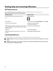
... not be available in your purchase invoice, packing slip, bill, or Dell product catalog. 88 Alienware products and online self-help resources Self-help blogs, drivers, software updates, and so on Alienware products and services using these online self-help resources: Table 15. Online help for sales, technical support, or customer service issues, see...
... not be available in your purchase invoice, packing slip, bill, or Dell product catalog. 88 Alienware products and online self-help resources Self-help blogs, drivers, software updates, and so on Alienware products and services using these online self-help resources: Table 15. Online help for sales, technical support, or customer service issues, see...
Setup and Specifications
Page 1
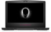
Alienware 15 R4 Setup and Specifications Computer Model: Alienware 15 R4 Regulatory Model: P69F Regulatory Type: P69F002
Alienware 15 R4 Setup and Specifications Computer Model: Alienware 15 R4 Regulatory Model: P69F Regulatory Type: P69F002
Setup and Specifications
Page 3
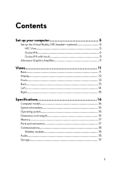
Contents Set up your computer 5 Set up the Virtual Reality (VR) headset-optional 5 HTC Vive 5 Oculus Rift 6 Oculus Rift with touch 8 Alienware Graphics Amplifier 9 Views 11 Base 11 Display 12 Front 13 Back 13 Left 14 Right 15 Specifications 16 Computer model 16 System information 16 Operating system 16 Dimensions and weight 16 Memory 17 Ports and connectors 17 Communications 18 Wireless module 18 Audio 18 Storage 19 3
Contents Set up your computer 5 Set up the Virtual Reality (VR) headset-optional 5 HTC Vive 5 Oculus Rift 6 Oculus Rift with touch 8 Alienware Graphics Amplifier 9 Views 11 Base 11 Display 12 Front 13 Back 13 Left 14 Right 15 Specifications 16 Computer model 16 System information 16 Operating system 16 Dimensions and weight 16 Memory 17 Ports and connectors 17 Communications 18 Wireless module 18 Audio 18 Storage 19 3
Setup and Specifications
Page 15
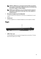
... the computer to enable charging. Right 1 USB 3.1 Gen 1 port Connect peripherals such as external storage devices and printers. Provides data transfer speeds up to 5 Gbps. 15 NOTE: Certain USB devices may not charge when the computer is turned off or in hibernate state, you must disconnect and connect it again to...
... the computer to enable charging. Right 1 USB 3.1 Gen 1 port Connect peripherals such as external storage devices and printers. Provides data transfer speeds up to 5 Gbps. 15 NOTE: Certain USB devices may not charge when the computer is turned off or in hibernate state, you must disconnect and connect it again to...
Setup and Specifications
Page 16
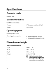
Specifications Computer model Alienware 15 R4 System information Table 1. Operating system Operating systems supported 8th Generation Intel Core i5/i7/i9 Intel CM246 • Windows 10 Home (64-bit) • Windows 10 Professional (64-bit) Dimensions and weight Table 3. Dimensions and weight Height Width Depth Weight 25.40 mm (1 in) 389 mm (15.31 in) 305 mm (12 in) 3.49 kg (7.69 lb) NOTE: The weight of your computer varies depending on the configuration ordered and the manufacturing variability. 16 System information Processor Chipset Operating system Table 2.
Specifications Computer model Alienware 15 R4 System information Table 1. Operating system Operating systems supported 8th Generation Intel Core i5/i7/i9 Intel CM246 • Windows 10 Home (64-bit) • Windows 10 Professional (64-bit) Dimensions and weight Table 3. Dimensions and weight Height Width Depth Weight 25.40 mm (1 in) 389 mm (15.31 in) 305 mm (12 in) 3.49 kg (7.69 lb) NOTE: The weight of your computer varies depending on the configuration ordered and the manufacturing variability. 16 System information Processor Chipset Operating system Table 2.
Setup and Specifications
Page 21
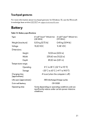
... specifications Type 4-cell "smart" lithium-ion 6-cell "smart" lithium-ion (68 WHr) (99 WHr) Weight (maximum) 0.33 kg (0.72 lb) 0.43 kg (0.94 lb) Voltage 15.20 VDC 11.40 VDC Dimensions: Height 13.50 mm (0.53 in) Width 259.60 mm (10.22 in) Depth 89.20 mm (3.51 in...
... specifications Type 4-cell "smart" lithium-ion 6-cell "smart" lithium-ion (68 WHr) (99 WHr) Weight (maximum) 0.33 kg (0.72 lb) 0.43 kg (0.94 lb) Voltage 15.20 VDC 11.40 VDC Dimensions: Height 13.50 mm (0.53 in) Width 259.60 mm (10.22 in) Depth 89.20 mm (3.51 in...
Setup and Specifications
Page 22
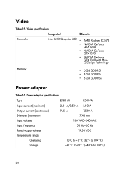
... range: Operating 0°C to 40°C (32°F to 104°F) Storage -40°C to 70°C (-40°F to 158°F) 22 Video Table 15.
... range: Operating 0°C to 40°C (32°F to 104°F) Storage -40°C to 70°C (-40°F to 158°F) 22 Video Table 15.
Setup and Specifications
Page 23
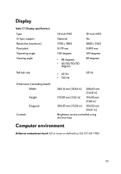
... FHD Optional 1920 x 1080 0.179 mm 140 degrees • 80 degrees • 60/60/50/50 degrees • 60 Hz • 120 Hz 15-inch UHD Yes 3840 x 2160 0.090 mm 140 degrees 80 degrees 60 Hz 344.16 mm (13.54 in) 345.60 mm (13.60 in) ...193.59 mm (7.62 in) 194.40 mm (7.65 in) 394.87 mm (15.54 in) 396.52 mm (15.61 in) Brightness can be controlled using shortcut keys Computer environment Airborne contaminant level: G2 or lower as defined by ISA-S71.04...
... FHD Optional 1920 x 1080 0.179 mm 140 degrees • 80 degrees • 60/60/50/50 degrees • 60 Hz • 120 Hz 15-inch UHD Yes 3840 x 2160 0.090 mm 140 degrees 80 degrees 60 Hz 344.16 mm (13.54 in) 345.60 mm (13.60 in) ...193.59 mm (7.62 in) 194.40 mm (7.65 in) 394.87 mm (15.54 in) 396.52 mm (15.61 in) Brightness can be controlled using shortcut keys Computer environment Airborne contaminant level: G2 or lower as defined by ISA-S71.04...
Setup and Specifications
Page 24
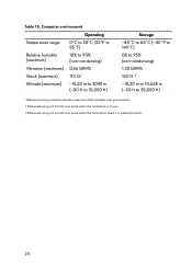
...176;C (32°F to 95°F) Relative humidity (maximum) 10% to 90% (non-condensing) Vibration (maximum) 0.66 GRMS Shock (maximum)* 110 G† Altitude (maximum) -15.20 m to 3048 m (-50 ft to 10,000 ft) Storage -40°C to 65°C (-40°F to 149°F) 0% to 95% (non-condensing) 1.30... GRMS 160 G ‡ -15.20 m to 10,668 m (-50 ft to 35,000 ft) * Measured using a random vibration spectrum that simulates user environment. † Measured using a 2 ms half-sine...
...176;C (32°F to 95°F) Relative humidity (maximum) 10% to 90% (non-condensing) Vibration (maximum) 0.66 GRMS Shock (maximum)* 110 G† Altitude (maximum) -15.20 m to 3048 m (-50 ft to 10,000 ft) Storage -40°C to 65°C (-40°F to 149°F) 0% to 95% (non-condensing) 1.30... GRMS 160 G ‡ -15.20 m to 10,668 m (-50 ft to 35,000 ft) * Measured using a random vibration spectrum that simulates user environment. † Measured using a 2 ms half-sine...


