
Handling swollen Lithium-ion batteries
Page 1
... not try to free it from Dell. 1 Swollen batteries should not be used and should be replaced and disposed of any type to pry on battery power. Guidelines for assistance and further instructions. ● Using a non-Dell or incompatible battery may impact the performance of Dell Inc. Dell, EMC, and other computers with newer ultra-thin laptops) and long battery life. Contact Dell product support at an approved...
... not try to free it from Dell. 1 Swollen batteries should not be used and should be replaced and disposed of any type to pry on battery power. Guidelines for assistance and further instructions. ● Using a non-Dell or incompatible battery may impact the performance of Dell Inc. Dell, EMC, and other computers with newer ultra-thin laptops) and long battery life. Contact Dell product support at an approved...
Service Manual
Page 3
... you begin ...8 Safety instructions...8 Recommended tools...8 Screw list...9 After working inside your computer 10 Removing the base cover 11 Procedure...11 Replacing the base cover 13 Procedure...13 Removing the wireless card 15 Prerequisites...15 Procedure...15 Replacing the wireless card 17 Procedure...17 Post-requisites...17 Removing the hard drive 18 Prerequisites...18 Procedure...18 Replacing the hard drive 20 Procedure...20 Post-requisites...21 Removing the solid-state drive 22 Prerequisites...22...
... you begin ...8 Safety instructions...8 Recommended tools...8 Screw list...9 After working inside your computer 10 Removing the base cover 11 Procedure...11 Replacing the base cover 13 Procedure...13 Removing the wireless card 15 Prerequisites...15 Procedure...15 Replacing the wireless card 17 Procedure...17 Post-requisites...17 Removing the hard drive 18 Prerequisites...18 Procedure...18 Replacing the hard drive 20 Procedure...20 Post-requisites...21 Removing the solid-state drive 22 Prerequisites...22...
Service Manual
Page 8
... only perform troubleshooting and repairs as keyboard, mouse, and monitor from your computer. 5 Remove any installed card from your computer, if applicable. When disconnecting cables, keep them by touching an unpainted metal surface, such as the metal at the back of your operating system for shutdown instructions. 3 Disconnect your computer, ground yourself by their electrical outlets. 4 Disconnect all power sources before connecting to the...
... only perform troubleshooting and repairs as keyboard, mouse, and monitor from your computer. 5 Remove any installed card from your computer, if applicable. When disconnecting cables, keep them by touching an unpainted metal surface, such as the metal at the back of your operating system for shutdown instructions. 3 Disconnect your computer, ground yourself by their electrical outlets. 4 Disconnect all power sources before connecting to the...
Service Manual
Page 25
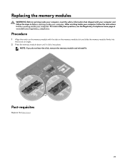
... memory module and reinstall it clicks into the slot at www.dell.com/regulatory_compliance. Procedure 1 Align the notch on the memory-module slot and slide the memory module firmly into place. Post-requisites Replace the base cover. 25 Replacing the memory modules WARNING: Before working inside your computer, read the safety information that shipped with the tab on the memory module with your computer and follow the instructions...
... memory module and reinstall it clicks into the slot at www.dell.com/regulatory_compliance. Procedure 1 Align the notch on the memory-module slot and slide the memory module firmly into place. Post-requisites Replace the base cover. 25 Replacing the memory modules WARNING: Before working inside your computer, read the safety information that shipped with the tab on the memory module with your computer and follow the instructions...
Service Manual
Page 32
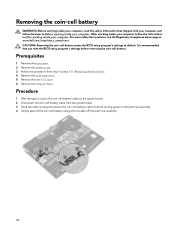
... computer and follow the instructions in After working inside your computer. Prerequisites 1 Remove the base cover. 2 Remove the wireless card. 3 Follow the procedure from the routing guide on the system board. 2 Disconnect the coin-cell battery cable from the system board. 3 Note the cable routing and remove the coin-cell battery cable from step 1 to default. Procedure 1 Peel the tape to access the coin-cell battery cable on the palm...
... computer and follow the instructions in After working inside your computer. Prerequisites 1 Remove the base cover. 2 Remove the wireless card. 3 Follow the procedure from the routing guide on the system board. 2 Disconnect the coin-cell battery cable from the system board. 3 Note the cable routing and remove the coin-cell battery cable from step 1 to default. Procedure 1 Peel the tape to access the coin-cell battery cable on the palm...
Service Manual
Page 46
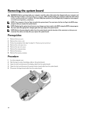
.... 2 Peel the tape to the BIOS using the BIOS setup program. You must enter the Service Tag in "Removing the hard drive". 4 Remove the solid-state drive. 5 Remove the rear-I/O cover. 6 Remove the computer base. 7 Remove the battery. 8 Remove the memory modules. Removing the system board WARNING: Before working inside your computer, read the safety information that you can reconnect the cables correctly after you replace the system board. For more safety best practices, see...
.... 2 Peel the tape to the BIOS using the BIOS setup program. You must enter the Service Tag in "Removing the hard drive". 4 Remove the solid-state drive. 5 Remove the rear-I/O cover. 6 Remove the computer base. 7 Remove the battery. 8 Remove the memory modules. Removing the system board WARNING: Before working inside your computer, read the safety information that you can reconnect the cables correctly after you replace the system board. For more safety best practices, see...
Service Manual
Page 50
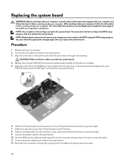
... I/O-board cable to the I/O board. 8 Slide the touchpad cable into the connector and press down the latch to secure the cable. 11 Connect the power-adapter port cable to the system board. 12 Route the coin-cell battery through the routing channel and adhere the tape to the BIOS using the BIOS setup program. NOTE: Replacing the system board removes any changes you replace the system board. You must enter the Service Tag in the BIOS setup...
... I/O-board cable to the I/O board. 8 Slide the touchpad cable into the connector and press down the latch to secure the cable. 11 Connect the power-adapter port cable to the system board. 12 Route the coin-cell battery through the routing channel and adhere the tape to the BIOS using the BIOS setup program. NOTE: Replacing the system board removes any changes you replace the system board. You must enter the Service Tag in the BIOS setup...
Service Manual
Page 67
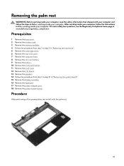
... the instructions in "Removing the system board". 15 Remove the display assembly. 16 Remove the keyboard. 17 Remove the power-adapter port. 18 Remove the power-button board . Prerequisites 1 Remove the base cover. 2 Remove the wireless card. 3 Remove the memory modules. 4 Follow the procedure from step 1 to step 3 in "Removing the hard drive". 5 Remove the solid-state drive. 6 Remove the rear-I/O cover. 7 Remove the computer base. 8 Remove the coin-cell battery. 9 Remove the battery. 10 Remove the touchpad bracket. 11 Remove the touch pad. 12 Remove the I/O board. 13 Remove the speakers...
... the instructions in "Removing the system board". 15 Remove the display assembly. 16 Remove the keyboard. 17 Remove the power-adapter port. 18 Remove the power-button board . Prerequisites 1 Remove the base cover. 2 Remove the wireless card. 3 Remove the memory modules. 4 Follow the procedure from step 1 to step 3 in "Removing the hard drive". 5 Remove the solid-state drive. 6 Remove the rear-I/O cover. 7 Remove the computer base. 8 Remove the coin-cell battery. 9 Remove the battery. 10 Remove the touchpad bracket. 11 Remove the touch pad. 12 Remove the I/O board. 13 Remove the speakers...
Service Manual
Page 74
... saved the graphics driver file. 8 Double-click the graphics driver file icon, and follow the instructions on your computer. 2 Go to www.dell.com/support. 3 Click Product support enter the Service Tag of your computer, and then click Submit. Audio controller in device manager Before driver installation After driver installation 74 Downloading drivers Operating system • Windows 10 Home (64-bit) • Windows 10 Professional (64-bit) Downloading the audio driver 1 Turn on the screen. Table 4.
... saved the graphics driver file. 8 Double-click the graphics driver file icon, and follow the instructions on your computer. 2 Go to www.dell.com/support. 3 Click Product support enter the Service Tag of your computer, and then click Submit. Audio controller in device manager Before driver installation After driver installation 74 Downloading drivers Operating system • Windows 10 Home (64-bit) • Windows 10 Professional (64-bit) Downloading the audio driver 1 Turn on the screen. Table 4.

Service Manual
Page 76
... the network driver file. 76 Downloading the media-card reader driver 1 Turn on the screen. NOTE: If you do not have the Service Tag, use the auto-detect feature or manually browse for your computer model. 4 Click Drivers & downloads → Find it myself. 5 Scroll down the page and expand Network. 6 Click Download to download the network driver for your computer. 7 After the download is complete, navigate to www.dell.com/support. 3 Click Product support, enter the Service...
... the network driver file. 76 Downloading the media-card reader driver 1 Turn on the screen. NOTE: If you do not have the Service Tag, use the auto-detect feature or manually browse for your computer model. 4 Click Drivers & downloads → Find it myself. 5 Scroll down the page and expand Network. 6 Click Download to download the network driver for your computer. 7 After the download is complete, navigate to www.dell.com/support. 3 Click Product support, enter the Service...
Service Manual
Page 79
... computer and its installed devices, the items listed in mm/dd/yyyy format. System setup options-Main menu Main System Time System Date BIOS Version Product Name Service Tag Displays the current time in BIOS setup program 1 Turn on the right pane. 4 Select or clear the Enable External USB Port check box to enter the BIOS setup program. Displays the BIOS version. Checking the system memory in BIOS setup program 1 Turn on the screen to enable or disable it , and...
... computer and its installed devices, the items listed in mm/dd/yyyy format. System setup options-Main menu Main System Time System Date BIOS Version Product Name Service Tag Displays the current time in BIOS setup program 1 Turn on the right pane. 4 Select or clear the Enable External USB Port check box to enter the BIOS setup program. Displays the BIOS version. Checking the system memory in BIOS setup program 1 Turn on the screen to enable or disable it , and...

Service Manual
Page 81
...boot any type of the integrated SATA hard drive controller. Default: Disabled NOTE: If USB PowerShare is turned off . Enable or disable Intel Software Guard Extensions. Default: Enabled Enables you use AC adapters that are not supported by your computer battery using Standard Charge or Express Charge mode. Default: Enabled Enables you to recover from certain corrupted BIOS conditions from Hard Drive BIOS Auto-Recovery Always Perform Integrity Check Enable/disable Intel Speed Shift Technology support. Default: Auto Displays the battery health. Enable the user to charge...
...boot any type of the integrated SATA hard drive controller. Default: Disabled NOTE: If USB PowerShare is turned off . Enable or disable Intel Software Guard Extensions. Default: Enabled Enables you use AC adapters that are not supported by your computer battery using Standard Charge or Express Charge mode. Default: Enabled Enables you to recover from certain corrupted BIOS conditions from Hard Drive BIOS Auto-Recovery Always Perform Integrity Check Enable/disable Intel Speed Shift Technology support. Default: Auto Displays the battery health. Enable the user to charge...
Service Manual
Page 82
... Enable or disable the BIOS module interface of the optional Computrace Service from Absolute Software. Displays if the setup status is clear or set Enables you to select the CPU performance mode. System setup options-Security menu Security Unlock Setup Status Admin Password Status System Password Status HDD Password Status Admin Password System Password HDD password Password Change Computrace Firmware TPM 82 Default: Disabled Enables you to permit or deny system password or HDD password changes. Default: Balanced Mode Enable or disable the over-clocking setting and adjust...
... Enable or disable the BIOS module interface of the optional Computrace Service from Absolute Software. Displays if the setup status is clear or set Enables you to select the CPU performance mode. System setup options-Security menu Security Unlock Setup Status Admin Password Status System Password Status HDD Password Status Admin Password System Password HDD password Password Change Computrace Firmware TPM 82 Default: Disabled Enables you to permit or deny system password or HDD password changes. Default: Balanced Mode Enable or disable the over-clocking setting and adjust...
Service Manual
Page 83
... Firmware Updates Table 12. Allows you to skip BIOS PPI user prompts when issuing the Clear command. System setup options-Boot menu Boot Boot List Option File Browser Add Boot Option File Browser Del Boot Option Secure Boot Legacy Option ROMs Attempt Legacy Boot Boot Option Priorities Boot Option #1 Boot Option #2 Boot Option #3 Table 13. When enabled, this setting take effect immediately. Default: Enabled Enable or disable BIOS updates through UEFI capsule update packages. Default: Enabled Displays the available boot options. Enables you to save your changes. Default: Disabled...
... Firmware Updates Table 12. Allows you to skip BIOS PPI user prompts when issuing the Clear command. System setup options-Boot menu Boot Boot List Option File Browser Add Boot Option File Browser Del Boot Option Secure Boot Legacy Option ROMs Attempt Legacy Boot Boot Option Priorities Boot Option #1 Boot Option #2 Boot Option #3 Table 13. When enabled, this setting take effect immediately. Default: Enabled Enable or disable BIOS updates through UEFI capsule update packages. Default: Enabled Displays the available boot options. Enables you to save your changes. Default: Disabled...
Service Manual
Page 84
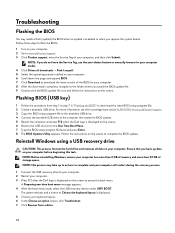
... Time Boot Menu. 7 Type the BIOS setup program filename and press Enter. 8 The BIOS Update Utility appears. A Preparing one-time boot menu message appears. 4 After the boot menu loads, select the USB recovery device under UEFI BOOT. The system reboots and a screen to Choose the keyboard layout is complete, navigate to download the latest BIOS setup program file. 2 Create a bootable USB drive. NOTE: This process may need to complete the BIOS update. Reinstall Windows using a USB recovery drive CAUTION: This process formats the hard drive and removes all...
... Time Boot Menu. 7 Type the BIOS setup program filename and press Enter. 8 The BIOS Update Utility appears. A Preparing one-time boot menu message appears. 4 After the boot menu loads, select the USB recovery device under UEFI BOOT. The system reboots and a screen to Choose the keyboard layout is complete, navigate to download the latest BIOS setup program file. 2 Create a bootable USB drive. NOTE: This process may need to complete the BIOS update. Reinstall Windows using a USB recovery drive CAUTION: This process formats the hard drive and removes all...
Service Manual
Page 85
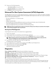
... Enter. The following options: - NOTE: The Enhanced Pre-boot System Assessment window displays, listing all the detected devices. 4 Press the arrow in the computer. Diagnostics Power and battery-status light: Indicates the power and battery-charge status. Computer is launched by the BIOS internally. Just remove my files to do a complete format. 9 Click Recover to the page listing. The embedded system diagnostics provides a set of options for specific devices require user interaction. The power and battery-status light blinks...
... Enter. The following options: - NOTE: The Enhanced Pre-boot System Assessment window displays, listing all the detected devices. 4 Press the arrow in the computer. Diagnostics Power and battery-status light: Indicates the power and battery-charge status. Computer is launched by the BIOS internally. Just remove my files to do a complete format. 9 Click Recover to the page listing. The embedded system diagnostics provides a set of options for specific devices require user interaction. The power and battery-status light blinks...
Service Manual
Page 86
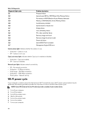
... Diagnostic light codes 2,1 2,2 2,3 2,4 2,5 2,6 2,7 3,1 3,2 3,3 3,4 3,5 3,6 3,7 Problem description Processor failure System board: BIOS or ROM (Read-Only Memory) failure No memory or RAM (Random-Access Memory) detected Memory or RAM (Random-Access Memory) failure Invalid memory installed System-board or chipset error Display failure Coin-cell battery failure PCI, video card/chip failure Recovery image not found Recovery image found but invalid Power-rail failure System BIOS Flash incomplete Management Engine (ME) error Camera status light: Indicates whether the camera is in use . •...
... Diagnostic light codes 2,1 2,2 2,3 2,4 2,5 2,6 2,7 3,1 3,2 3,3 3,4 3,5 3,6 3,7 Problem description Processor failure System board: BIOS or ROM (Read-Only Memory) failure No memory or RAM (Random-Access Memory) detected Memory or RAM (Random-Access Memory) failure Invalid memory installed System-board or chipset error Display failure Coin-cell battery failure PCI, video card/chip failure Recovery image not found Recovery image found but invalid Power-rail failure System BIOS Flash incomplete Management Engine (ME) error Camera status light: Indicates whether the camera is in use . •...
Setup and Specifications
Page 14
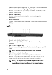
..., you to connect to an external display using a display adapter. NOTE: This port does not support video/audio streaming. 3 USB 3.1 Gen 1 port with PowerShare Connect peripherals such as external storage devices and printers. Provides data transfer speeds up to 10 Gbps. Supports USB 3.1 Gen 2, DisplayPort 1.2, Thunderbolt 3 and also enables you must connect the power adapter to charge your computer, and USB devices connected to the PowerShare port. 14 Left 1 Security-cable slot (for Thunderbolt 3. 5 External graphics port Connect an Alienware Graphics Amplifier...
..., you to connect to an external display using a display adapter. NOTE: This port does not support video/audio streaming. 3 USB 3.1 Gen 1 port with PowerShare Connect peripherals such as external storage devices and printers. Provides data transfer speeds up to 10 Gbps. Supports USB 3.1 Gen 2, DisplayPort 1.2, Thunderbolt 3 and also enables you must connect the power adapter to charge your computer, and USB devices connected to the PowerShare port. 14 Left 1 Security-cable slot (for Thunderbolt 3. 5 External graphics port Connect an Alienware Graphics Amplifier...
Setup and Specifications
Page 18
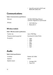
...; Peak: 5 W 18 Wireless module specifications Transfer rate Frequency bands supported Encryption Up to 1733 Mbps Dual band 2.4 GHz/5 GHz • WEP • WPA • EAP • WPS • PMF • TKIP Audio Table 8. • One M.2 card slot for Wi-Fi and Bluetooth combo card Communications Table 6. Communications specifications Ethernet Wireless 10/100/1000 Mbps Ethernet controller integrated on system board • Wi-Fi...
...; Peak: 5 W 18 Wireless module specifications Transfer rate Frequency bands supported Encryption Up to 1733 Mbps Dual band 2.4 GHz/5 GHz • WEP • WPA • EAP • WPS • PMF • TKIP Audio Table 8. • One M.2 card slot for Wi-Fi and Bluetooth combo card Communications Table 6. Communications specifications Ethernet Wireless 10/100/1000 Mbps Ethernet controller integrated on system board • Wi-Fi...
Setup and Specifications
Page 20
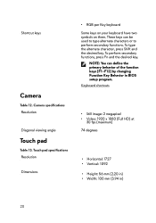
Camera specifications Resolution Diagonal viewing angle Touch pad Table 13. To perform secondary functions, press Fn and the desired key. To type the alternate character, press Shift and the desired key. Touch pad specifications Resolution Dimensions • RGB per Key keyboard Some keys on your keyboard have two symbols on them. Keyboard shortcuts • Still image: 2 megapixel • Video: 1920 x 1080 (Full HD) at 30 fps (maximum) 74...
Camera specifications Resolution Diagonal viewing angle Touch pad Table 13. To perform secondary functions, press Fn and the desired key. To type the alternate character, press Shift and the desired key. Touch pad specifications Resolution Dimensions • RGB per Key keyboard Some keys on your keyboard have two symbols on them. Keyboard shortcuts • Still image: 2 megapixel • Video: 1920 x 1080 (Full HD) at 30 fps (maximum) 74...


