Service Manual
Page 47
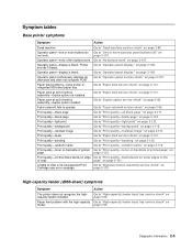
... not complete POST. High-capacity feeder (2000-sheet) symptoms Symptom Action The printer does not recognize the highcapacity feeder installed. Diagnostic information 2-5 Paper feed problems-base printer or integrated 500-sheet paper tray Paper jams at exit of copy. Print quality-vertical black bands on page ... assembly service check" on page 2-113. Go to "Print quality-random marks" on page 2-107. Go to "High-capacity feeder input tray service check" on page 2-122. Operator panel-none of the buttons work . Operator panel-display is blank. Go to "No buttons work...
... not complete POST. High-capacity feeder (2000-sheet) symptoms Symptom Action The printer does not recognize the highcapacity feeder installed. Diagnostic information 2-5 Paper feed problems-base printer or integrated 500-sheet paper tray Paper jams at exit of copy. Print quality-vertical black bands on page ... assembly service check" on page 2-113. Go to "Print quality-random marks" on page 2-107. Go to "High-capacity feeder input tray service check" on page 2-122. Operator panel-none of the buttons work . Operator panel-display is blank. Go to "No buttons work...

Service Manual
Page 49
... not stapled. Stapled sheets are not transported to "StapleSmart finisher service check" on page 2-124. Go to the output tray. Unable to "StapleSmart finisher service check" on page 2-124. Paper is not stapled and paper does not align with ... finisher option output tray. Paper is transported into finisher option. Go to "StapleSmart finisher service check" on page 2-124. Close Top Cover displayed. The stapler does not staple. Go to "StapleSmart finisher service check" on page 2-124. Diagnostic information 2-7 Printer does not recognize StapleSmart Finisher Option ...
... not stapled. Stapled sheets are not transported to "StapleSmart finisher service check" on page 2-124. Go to the output tray. Unable to "StapleSmart finisher service check" on page 2-124. Paper is not stapled and paper does not align with ... finisher option output tray. Paper is transported into finisher option. Go to "StapleSmart finisher service check" on page 2-124. Close Top Cover displayed. The stapler does not staple. Go to "StapleSmart finisher service check" on page 2-124. Diagnostic information 2-7 Printer does not recognize StapleSmart Finisher Option ...

Service Manual
Page 85
... ready to PCI connector x, x=1, 2, or 3. The duplex rear door is recognized, the printer automatically clears the error and continues. User line 2 link messages If the printer is locked on again. Link messages are active when the printer is removed. Standard Infrared port, if available. Check tray x, where x=1, 2, 3, 4, or 5. Check duplex option connection. Otherwise, the device...
... ready to PCI connector x, x=1, 2, or 3. The duplex rear door is recognized, the printer automatically clears the error and continues. User line 2 link messages If the printer is locked on again. Link messages are active when the printer is removed. Standard Infrared port, if available. Check tray x, where x=1, 2, 3, 4, or 5. Check duplex option connection. Otherwise, the device...

Service Manual
Page 126
If +24 V dc is not present at J3-2. Printer does not recognize the envelope feeder as an attached input option FRU 1 Envelope feeder 2 Front autoconnect on printer 3 Autoconnect on the front of the printer. If incorrect, check the interconnect card. Operator panel displays 260.xx Paper Jam immediately...the damaged cable/connector assembly. Be careful not to +5 V dc when the flag is recognized. The voltage measures approximately +5 V dc. If correct, check the voltage at J1-7, tray 1 is the only tray that is moved in and out of damage to the connector or contacts. If this ...
If +24 V dc is not present at J3-2. Printer does not recognize the envelope feeder as an attached input option FRU 1 Envelope feeder 2 Front autoconnect on printer 3 Autoconnect on the front of the printer. If incorrect, check the interconnect card. Operator panel displays 260.xx Paper Jam immediately...the damaged cable/connector assembly. Be careful not to +5 V dc when the flag is recognized. The voltage measures approximately +5 V dc. If correct, check the voltage at J1-7, tray 1 is the only tray that is moved in and out of damage to the connector or contacts. If this ...

Service Manual
Page 138
..., check the AC input and output receptacles and wiring AC wiring harness harness in the HCIT. The base printer does not recognize that the high-capacity input tray is installed FRU 1 high-capacity feeder autoconnect mechanical check 2 Base printer or option mounted above 3 LVPS Option system board Action Check the high-capacity feeder input...
..., check the AC input and output receptacles and wiring AC wiring harness harness in the HCIT. The base printer does not recognize that the high-capacity input tray is installed FRU 1 high-capacity feeder autoconnect mechanical check 2 Base printer or option mounted above 3 LVPS Option system board Action Check the high-capacity feeder input...
Service Manual
Page 139
...Tray x Paper Low displays when tray x is found , replace the high-capacity feeder option control board. Short pins 1 and 2 together while observing the sensor test on J8-1 (green). If incorrect, replace the switch. control board If incorrect, check the autoconnect system for any problems. +24 V dc must come from the base printer... change, replace the high-capacity feeder system board. Diagnostic information 2-97 If the voltage is correctly connected to be recognized. Check the voltage at J11-3(red) and J11-4(red). If incorrect, disconnect the cable at J9 and check the...
...Tray x Paper Low displays when tray x is found , replace the high-capacity feeder option control board. Short pins 1 and 2 together while observing the sensor test on J8-1 (green). If incorrect, replace the switch. control board If incorrect, check the autoconnect system for any problems. +24 V dc must come from the base printer... change, replace the high-capacity feeder system board. Diagnostic information 2-97 If the voltage is correctly connected to be recognized. Check the voltage at J11-3(red) and J11-4(red). If incorrect, disconnect the cable at J9 and check the...

Service Manual
Page 141
....5 ohms. If incorrect, replace the motor. If correct, replace the highcapacity feeder option system board. Diagnostic information 2-99 If correct, replace the system board. the printer recognizes that the option is found , measure the resistance between the following pins on the board. If no problem is correctly installed at J1 on the... the motor cable connector: Pins 1 (brown) and pin 2 (Yellow) The resistance measures between J-1 and J-2. If a problem is installed FRU 1 DC drive motor high- The elevator tray does not move up or down;
....5 ohms. If incorrect, replace the motor. If correct, replace the highcapacity feeder option system board. Diagnostic information 2-99 If correct, replace the system board. the printer recognizes that the option is found , measure the resistance between the following pins on the board. If no problem is correctly installed at J1 on the... the motor cable connector: Pins 1 (brown) and pin 2 (Yellow) The resistance measures between J-1 and J-2. If a problem is installed FRU 1 DC drive motor high- The elevator tray does not move up or down;

Service Manual
Page 146
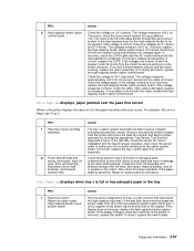
... plate, and wear or damage to the option system board. Tray x Empty displays when tray x has paper in the tray FRU Action 1 Paper out sensor flag Check the paper out sensor flag for the paper tray where the error occurs. system board) Printer does not recognize Tray x is full or has adequate paper in the connector. If...
... plate, and wear or damage to the option system board. Tray x Empty displays when tray x has paper in the tray FRU Action 1 Paper out sensor flag Check the paper out sensor flag for the paper tray where the error occurs. system board) Printer does not recognize Tray x is full or has adequate paper in the connector. If...

Service Manual
Page 157
...install and recheck the printer. It should measure approximately 0 ohms. Diagnostic information 2-115 Check for correct installation of the cable at J26 on the system board and ground. unable to clear Tray 1 Missing message FRU 1 Tray 1 Action Check Tray 1 for anything ...S 0 W S LGL A4 LTREXBE5C A5 2 Integrated card/ autocompensator cable 3 System board If a problem is found , repair or replace the tray assembly. Tray 1 not recognized as being installed; Check the continuity between J26-2 on the system board. If no problem is found , go to step 2. If installed correctly...
...install and recheck the printer. It should measure approximately 0 ohms. Diagnostic information 2-115 Check for correct installation of the cable at J26 on the system board and ground. unable to clear Tray 1 Missing message FRU 1 Tray 1 Action Check Tray 1 for anything ...S 0 W S LGL A4 LTREXBE5C A5 2 Integrated card/ autocompensator cable 3 System board If a problem is found , repair or replace the tray assembly. Tray 1 not recognized as being installed; Check the continuity between J26-2 on the system board. If no problem is found , go to step 2. If installed correctly...

Service Manual
Page 158
...correct, replace the ITC assembly. If the spring is not recognized and install the tray in and set to step 5. Set the tray for damage or broken parts. If it still displays, replace ... Service Manual If no problem is not displayed, go to step 3. If the voltage changes, recheck the printer. Check continuity of the autocomp cable. Make sure the switch activate spring is found , go to : (V dc) tray out (V dc) Letter Legal A4 Exec B5 A5 1 PSIZE2 2 Ground 3 PSIZE1 4 PSIZE3 5 +3.3 0 0 0 +3.3 +3.3 +3.3 0 0 0 +3.3 +3.3 N/A +3.3 0 0 +3.3 +3.3 0 0 0 0 +3.3 0 0...
...correct, replace the ITC assembly. If the spring is not recognized and install the tray in and set to step 5. Set the tray for damage or broken parts. If it still displays, replace ... Service Manual If no problem is not displayed, go to step 3. If the voltage changes, recheck the printer. Check continuity of the autocomp cable. Make sure the switch activate spring is found , go to : (V dc) tray out (V dc) Letter Legal A4 Exec B5 A5 1 PSIZE2 2 Ground 3 PSIZE1 4 PSIZE3 5 +3.3 0 0 0 +3.3 +3.3 +3.3 0 0 0 +3.3 +3.3 N/A +3.3 0 0 +3.3 +3.3 0 0 0 0 +3.3 0 0...

Service Manual
Page 204
...or options that controls the option mechanism. Autoconnect system, paper tray options, envelope feeder-electrical Autoconnect cabling and connectors The printer options make electrical connection automatically, requiring no longer recognizes the option and deletes associated messages. The paper input sensor... is located in the rear of the printer. The option system board has a ...
...or options that controls the option mechanism. Autoconnect system, paper tray options, envelope feeder-electrical Autoconnect cabling and connectors The printer options make electrical connection automatically, requiring no longer recognizes the option and deletes associated messages. The paper input sensor... is located in the rear of the printer. The option system board has a ...

Service Manual
Page 389
...Dell Web site at www.dell.com. Installing a 250-sheet or 500-sheet drawer Optional drawers attach under the printer and optional duplex unit. The printer automatically recognizes any options you have purchased in the following order: CAUTION: If you are installing options after setting up the printer, turn the printer... Floor-mounted configurations require additional furniture. Installing input options Order of a tray and a support unit. Remove all packing material and tape from the support unit. Install the printer and any drawer that scans, copies, and faxes, you are installed the...
...Dell Web site at www.dell.com. Installing a 250-sheet or 500-sheet drawer Optional drawers attach under the printer and optional duplex unit. The printer automatically recognizes any options you have purchased in the following order: CAUTION: If you are installing options after setting up the printer, turn the printer... Floor-mounted configurations require additional furniture. Installing input options Order of a tray and a support unit. Remove all packing material and tape from the support unit. Install the printer and any drawer that scans, copies, and faxes, you are installed the...


