
User Manual
Page 2
All rights reserved. Default login information Management IP Address: 192.168.0.32 User name: admin Password: 123456 Copyright@2014 D-Link System, Inc. D-Link Document - All Rights Reserved. 2 Copyright Copyright@2014, D-Link Corporation, Inc. User Manual Trademarks All products and trade names used in this manual are trademarks or registered trademarks of their respective companies.
All rights reserved. Default login information Management IP Address: 192.168.0.32 User name: admin Password: 123456 Copyright@2014 D-Link System, Inc. D-Link Document - All Rights Reserved. 2 Copyright Copyright@2014, D-Link Corporation, Inc. User Manual Trademarks All products and trade names used in this manual are trademarks or registered trademarks of their respective companies.

User Manual
Page 3
...SATA), technology. Cautions indicate that you to service, change, disassemble or upgrade the equipment's components by yourself. Copyright@2014 D-Link System, Inc. All Rights Reserved. 3 Refer all servicing to important safety and operational information. Conventions The following symbols to draw...authorized service personnel. User Manual 0 About This Manual This manual introduces the D-Link storage system and it assumes that failure to the software or hardware. Preface D-Link Document - Information contained in this manual has been reviewed for accuracy, but ...
...SATA), technology. Cautions indicate that you to service, change, disassemble or upgrade the equipment's components by yourself. Copyright@2014 D-Link System, Inc. All Rights Reserved. 3 Refer all servicing to important safety and operational information. Conventions The following symbols to draw...authorized service personnel. User Manual 0 About This Manual This manual introduces the D-Link storage system and it assumes that failure to the software or hardware. Preface D-Link Document - Information contained in this manual has been reviewed for accuracy, but ...

User Manual
Page 4
... on a window, other than the window title, including menus, menu options, buttons, fields, and labels. Indicates that you must choose either a or b. Example: [ a | b ] Copyright@2014 D-Link System, Inc. Indicates required or expected values. Indicates the default value. Example: { a | b } indicates that you can choose a, b, or nothing. Indicates optional values. Example: [ a | b ]...All Rights Reserved. 4 Indicates a variable, which is a placeholder for actual text provided by the user or system. Example: copy . Indicates all options or arguments. D-Link Document -
... on a window, other than the window title, including menus, menu options, buttons, fields, and labels. Indicates that you must choose either a or b. Example: [ a | b ] Copyright@2014 D-Link System, Inc. Indicates required or expected values. Indicates the default value. Example: { a | b } indicates that you can choose a, b, or nothing. Indicates optional values. Example: [ a | b ]...All Rights Reserved. 4 Indicates a variable, which is a placeholder for actual text provided by the user or system. Example: copy . Indicates all options or arguments. D-Link Document -

User Manual
Page 5
... ...27 Power off the System...28 Chapter 3 QUICK SETUP...29 MANAGEMENT INTERFACES ...29 Serial Console...29 Secure Shell Remote Access...29 LCD ...30 Copyright@2014 D-Link System, Inc. All Rights Reserved...
... ...27 Power off the System...28 Chapter 3 QUICK SETUP...29 MANAGEMENT INTERFACES ...29 Serial Console...29 Secure Shell Remote Access...29 LCD ...30 Copyright@2014 D-Link System, Inc. All Rights Reserved...

User Manual
Page 6
D-Link Document - All Rights Reserved. 6 User Manual Web UI ...32 HOW TO USE THE GUIDED CONFIGURATIONS ...35 Quick Installation Tool ...35 Volume Creation Wizard ...40 Chapter 4 ... ...83 Event log ...84 Upgrade ...85 Firmware Synchronization (Only available in Dual controller models 86 Reset to Factory Defaults...87 Configuration Backup...87 Copyright@2014 D-Link System, Inc.
D-Link Document - All Rights Reserved. 6 User Manual Web UI ...32 HOW TO USE THE GUIDED CONFIGURATIONS ...35 Quick Installation Tool ...35 Volume Creation Wizard ...40 Chapter 4 ... ...83 Event log ...84 Upgrade ...85 Firmware Synchronization (Only available in Dual controller models 86 Reset to Factory Defaults...87 Configuration Backup...87 Copyright@2014 D-Link System, Inc.

User Manual
Page 7
D-Link Document - User Manual Volume Restoration ...88 Reboot and Shutdown ...89 PERFORMANCE MONITOR ...90 Disk...90 iSCSI...90 Chapter 5 ADVANCED OPERATIONS ...92 VOLUME REBUILD ...92 MIGRATE ... Controller Mode...109 Recommend iSNS Server...109 SNAPSHOTS ...110 Take a Snapshot ...110 Cleanup Snapshots...111 Schedule Snapshots ...112 Rollback...112 Snapshot Constraint...113 Copyright@2014 D-Link System, Inc. All Rights Reserved. 7
D-Link Document - User Manual Volume Restoration ...88 Reboot and Shutdown ...89 PERFORMANCE MONITOR ...90 Disk...90 iSCSI...90 Chapter 5 ADVANCED OPERATIONS ...92 VOLUME REBUILD ...92 MIGRATE ... Controller Mode...109 Recommend iSNS Server...109 SNAPSHOTS ...110 Take a Snapshot ...110 Cleanup Snapshots...111 Schedule Snapshots ...112 Rollback...112 Snapshot Constraint...113 Copyright@2014 D-Link System, Inc. All Rights Reserved. 7

User Manual
Page 8
D-Link Document - All Rights Reserved. 8 User Manual CLONE ...115 Setup Clone ...115 Start and Stop Clone ...116 Schedule Clone...116 Cloning Options...117 Clear Clone ...118 ... ...138 SYSTEM BUZZER ...138 EVENT NOTIFICATIONS...138 Chapter 7 SOFTWARE APPLICATION...148 MICROSOFT ISCSI INITIATOR...148 Connect to iSCSI Target...148 Setup MPIO ...149 Copyright@2014 D-Link System, Inc.
D-Link Document - All Rights Reserved. 8 User Manual CLONE ...115 Setup Clone ...115 Start and Stop Clone ...116 Schedule Clone...116 Cloning Options...117 Clear Clone ...118 ... ...138 SYSTEM BUZZER ...138 EVENT NOTIFICATIONS...138 Chapter 7 SOFTWARE APPLICATION...148 MICROSOFT ISCSI INITIATOR...148 Connect to iSCSI Target...148 Setup MPIO ...149 Copyright@2014 D-Link System, Inc.

User Manual
Page 9
D-Link Document - User Manual Setup MC/S ...149 Disconnect ...150 Chapter 8 Chapter 9 GLOSSARY AND ACRONYM LIST ...151 INDEX ...153 Copyright@2014 D-Link System, Inc. All Rights Reserved. 9
D-Link Document - User Manual Setup MC/S ...149 Disconnect ...150 Chapter 8 Chapter 9 GLOSSARY AND ACRONYM LIST ...151 INDEX ...153 Copyright@2014 D-Link System, Inc. All Rights Reserved. 9

User Manual
Page 10
... network (SAN) solution for virtualized server environments and the glowing demand for the following models. DSN-6200 Series: 6 x GbE iSCSI ports per controller. (DSN-6210: single controller, DSN-6220: dual-active controller). DSN-6500 Series: 2 x 10GbE iSCSI ports (SFP+) + 2 x GbE iSCSI ports per controller. (DSN- 6510: single controller, DSN-6520: dual-active controller). Overview D-Link Document -
... network (SAN) solution for virtualized server environments and the glowing demand for the following models. DSN-6200 Series: 6 x GbE iSCSI ports per controller. (DSN-6210: single controller, DSN-6220: dual-active controller). DSN-6500 Series: 2 x 10GbE iSCSI ports (SFP+) + 2 x GbE iSCSI ports per controller. (DSN- 6510: single controller, DSN-6520: dual-active controller). Overview D-Link Document -

User Manual
Page 11
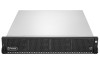
All Rights Reserved. 11 User Manual Package Contents The package contains the following items: D-Link DSN-6200/DSN-6500 Series 1GbE/10GbE IP SAN STORAGE (x1) HDD trays (x12) Power cords (x2) RS-232 cables (x2), one is for console (... for drives and rail kit (x1 packet) CD Quick Installation Guide Hardware This section provides basic information about the hardware components. Copyright@2014 D-Link System, Inc. D-Link Document -
All Rights Reserved. 11 User Manual Package Contents The package contains the following items: D-Link DSN-6200/DSN-6500 Series 1GbE/10GbE IP SAN STORAGE (x1) HDD trays (x12) Power cords (x2) RS-232 cables (x2), one is for console (... for drives and rail kit (x1 packet) CD Quick Installation Guide Hardware This section provides basic information about the hardware components. Copyright@2014 D-Link System, Inc. D-Link Document -

User Manual
Page 12
... management). OFF: There is designed specifically for a LCD screen by the right front handle; All Rights Reserved. 12 The default resets include: Copyright@2014 D-Link System, Inc. a USB interface for USB LCD usage. It DOES NOT offer external USB storage function. User Manual There is a power switch by the left...: Red: System failure. Off: System OK. 1 2 Number 1 2 Description Power button and power LED: Blue: Power ON. Off: Power OFF. Front View D-Link Document -
... management). OFF: There is designed specifically for a LCD screen by the right front handle; All Rights Reserved. 12 The default resets include: Copyright@2014 D-Link System, Inc. a USB interface for USB LCD usage. It DOES NOT offer external USB storage function. User Manual There is a power switch by the left...: Red: System failure. Off: System OK. 1 2 Number 1 2 Description Power button and power LED: Blue: Power ON. Off: Power OFF. Front View D-Link Document -

User Manual
Page 13
... Management IP Address: 192.168.0.32 User Name: admin Password: 123456 USB LCD comes as an optional device for the DSN-6200/6500 Series. Both the USB port on the front left handle and the USB port on the controller itself support the LCD function. Up... install SAS drives: align the edge of the drive to the back end of tray; Copyright@2014 D-Link System, Inc. The standard unit doesn't include an USB LCD. Down button. All Rights Reserved. 13 D-Link Document - However, the USB port doesn't support external USB storage function. 1 7 23 456 Number 1 2 3 4 5 6 7...
... Management IP Address: 192.168.0.32 User Name: admin Password: 123456 USB LCD comes as an optional device for the DSN-6200/6500 Series. Both the USB port on the front left handle and the USB port on the controller itself support the LCD function. Up... install SAS drives: align the edge of the drive to the back end of tray; Copyright@2014 D-Link System, Inc. The standard unit doesn't include an USB LCD. Down button. All Rights Reserved. 13 D-Link Document - However, the USB port doesn't support external USB storage function. 1 7 23 456 Number 1 2 3 4 5 6 7...

User Manual
Page 14
...Off: The drive is not being accessed or there is inserted and operational. Red: Drive failure. Off: No drive in the tray. D-Link Document - Tray removal handle. User Manual SAS Drive The front of each disk tray has four components: 3 4 SATA Drive 1 2 This table below provides ...details about the front components of a disk tray. Latch to release the tray. 3TB / 6G MUX Board Limitation DSN-6200/6500 Series: 2TB SATA 2TB SAS System Single upgradable Dual No 6G MUX board No 6G MUX board No No No No HDD Type...
...Off: The drive is not being accessed or there is inserted and operational. Red: Drive failure. Off: No drive in the tray. D-Link Document - Tray removal handle. User Manual SAS Drive The front of each disk tray has four components: 3 4 SATA Drive 1 2 This table below provides ...details about the front components of a disk tray. Latch to release the tray. 3TB / 6G MUX Board Limitation DSN-6200/6500 Series: 2TB SATA 2TB SAS System Single upgradable Dual No 6G MUX board No 6G MUX board No No No No HDD Type...

User Manual
Page 15
...Unit (PSU2). 1 8 9 5 6 2 3 This table describes the rear components. 4 7 Copyright@2014 D-Link System, Inc. SATA 6Gb/s SATA 3Gb/s SATA 1.5Gb/s 3TB SAS SAS 6Gb/s SAS 3Gb/s D-Link Document - Fan Module (FAN3 / FAN4). All Rights Reserved. 15 User Manual SATA 6Gb/s SATA 3Gb/s SATA 6Gb.../s SATA 3Gb/s SATA 6Gb/s SATA 1.5Gb/s Without MUX Board 2794 GB SAS 6Gb/s SAS 3Gb/s Rear View The following example shows the DSN-6220 chassis: 5 ...
...Unit (PSU2). 1 8 9 5 6 2 3 This table describes the rear components. 4 7 Copyright@2014 D-Link System, Inc. SATA 6Gb/s SATA 3Gb/s SATA 1.5Gb/s 3TB SAS SAS 6Gb/s SAS 3Gb/s D-Link Document - Fan Module (FAN3 / FAN4). All Rights Reserved. 15 User Manual SATA 6Gb/s SATA 3Gb/s SATA 6Gb.../s SATA 3Gb/s SATA 6Gb/s SATA 1.5Gb/s Without MUX Board 2794 GB SAS 6Gb/s SAS 3Gb/s Rear View The following example shows the DSN-6220 chassis: 5 ...

User Manual
Page 16
... data on the cache. RS 232 port for the future design purpose. 1GbE Link LED (All): Orange: Asserted when a 1G link is established and maintained. Green: Asserted when a 100M link is establish and maintained. 1GbE Access LED (All): Blinking green: ... along with any receive activity. 10GbE Link LED (DSN-6500): Orange: Asserted when a 1G link is established and maintained. Blue: Asserted when a 10G link is establish and maintained. 10GbE Access LED (DSN-6500): Yellow: Asserted when the link is the Slave controller. Management port....
... data on the cache. RS 232 port for the future design purpose. 1GbE Link LED (All): Orange: Asserted when a 1G link is established and maintained. Green: Asserted when a 100M link is establish and maintained. 1GbE Access LED (All): Blinking green: ... along with any receive activity. 10GbE Link LED (DSN-6500): Orange: Asserted when a 1G link is established and maintained. Blue: Asserted when a 10G link is establish and maintained. 10GbE Access LED (DSN-6500): Yellow: Asserted when the link is the Slave controller. Management port....

User Manual
Page 17
... storage device. User Manual 9 5 6 2 3 4 7 DSN-6500 (2 x 10GbE iSCSI (SFP+) + 2 x GbE iSCSI) controller: 1 9 5 6 2 3 DSN-6020 (6G SAS) JBOD controller: 4 7 7 2 7 RAID Concepts RAID is the abbreviation of Redundant Array of RAID is to combine multiple drives together to form one large logical drive. All Rights Reserved. 17 Copyright@2014 D-Link System, Inc. The basic idea...
... storage device. User Manual 9 5 6 2 3 4 7 DSN-6500 (2 x 10GbE iSCSI (SFP+) + 2 x GbE iSCSI) controller: 1 9 5 6 2 3 DSN-6020 (6G SAS) JBOD controller: 4 7 7 2 7 RAID Concepts RAID is the abbreviation of Redundant Array of RAID is to combine multiple drives together to form one large logical drive. All Rights Reserved. 17 Copyright@2014 D-Link System, Inc. The basic idea...

User Manual
Page 18
...18 LUN 1 VD 1 LUN 2 VD 2 LUN 3 VD + RG + + PD 1 PD 2 PD 3 DS Cache Volume RAM Copyright@2014 D-Link System, Inc. User Manual RAID Levels There are various RAID levels with parity on the dedicated disk. Min. It describes the relationship of Just a Bunch... Of Disks. D-Link Document - It has N copies of Drives 1 2 N 3 3 4 4 4 6 6 8 1 Volume Relationship The following graphic is the volume structure which D-Link has designed. Striping with interspersed parity over the member disks. 2-dimensional parity protection...
...18 LUN 1 VD 1 LUN 2 VD 2 LUN 3 VD + RG + + PD 1 PD 2 PD 3 DS Cache Volume RAM Copyright@2014 D-Link System, Inc. User Manual RAID Levels There are various RAID levels with parity on the dedicated disk. Min. It describes the relationship of Just a Bunch... Of Disks. D-Link Document - It has N copies of Drives 1 2 N 3 3 4 4 4 6 6 8 1 Volume Relationship The following graphic is the volume structure which D-Link has designed. Striping with interspersed parity over the member disks. 2-dimensional parity protection...

User Manual
Page 19
...common IP infrastructures. The iSCSI initiator requests or initiates any iSCSI communication. All Rights Reserved. 19 IP-SANs also include mechanisms for linking storage devices with any type of network (Ethernet, Fast Ethernet, Gigabit Ethernet, and 10 Gigabit Ethernet) and combination of storage ... Area Networks) which encapsulates SCSI (Small Computer System Interface) commands and data in the connection. IP SANs are initiator and target. D-Link Document - User Manual One RG (RAID group) consists of a set of storage volumes by any type and brand of operating systems ...
...common IP infrastructures. The iSCSI initiator requests or initiates any iSCSI communication. All Rights Reserved. 19 IP-SANs also include mechanisms for linking storage devices with any type of network (Ethernet, Fast Ethernet, Gigabit Ethernet, and 10 Gigabit Ethernet) and combination of storage ... Area Networks) which encapsulates SCSI (Small Computer System Interface) commands and data in the connection. IP SANs are initiator and target. D-Link Document - User Manual One RG (RAID group) consists of a set of storage volumes by any type and brand of operating systems ...

User Manual
Page 20
All Rights Reserved. 20 Host (initiator) SAS HBA SAS device 1 (target) Copyright@2014 D-Link System, Inc. D-Link Document - User Manual The target is the device which controls and serves volumes or virtual volumes. The target is the storage device itself or an ...
All Rights Reserved. 20 Host (initiator) SAS HBA SAS device 1 (target) Copyright@2014 D-Link System, Inc. D-Link Document - User Manual The target is the device which controls and serves volumes or virtual volumes. The target is the storage device itself or an ...

User Manual
Page 21
... The plan should setup automatically. For an iSCSI dual-controller system, install an iSNS server on the same network as the D-Link storage system. Connection cables: 。 Use CAT 5e, or CAT 6 (recommend) network cables for the management port and iSCSI... the static IP addresses, the subnet mask, and the default gateway. Switches 。 DSN-6200: Gigabit switches (recommended) or Gigabit switches with VLAN / LCAP / Trunking (optional). 。 DSN-6500: Gigabit switches (recommended) or 10 Gigabit switches with a Gigabit Ethernet NIC (recommend) on the...
... The plan should setup automatically. For an iSCSI dual-controller system, install an iSNS server on the same network as the D-Link storage system. Connection cables: 。 Use CAT 5e, or CAT 6 (recommend) network cables for the management port and iSCSI... the static IP addresses, the subnet mask, and the default gateway. Switches 。 DSN-6200: Gigabit switches (recommended) or Gigabit switches with VLAN / LCAP / Trunking (optional). 。 DSN-6500: Gigabit switches (recommended) or 10 Gigabit switches with a Gigabit Ethernet NIC (recommend) on the...