
Product Manual
Page 3
...DGS-3120 Series Managed Switch Web UI Reference Guide Table of Contents Intended Readers...1 Typographical Conventions...1 Notes, Notices and Cautions...1 Chapter 1 Web-based Switch Configuration 2 Introduction ...2 Login to the Web Manager...2 Web-based User Interface ...2 Areas of the User Interface...3 Web Pages...4 Chapter 2 System Configuration 5 Device Information ...5 System...System Log configuration...14 System Log Settings...14 System Log Server Settings ...15 System Log...16 System Log & Trap Settings...16 System Severity Settings...17 Time Range Settings...18 Port Group Settings (EI...
...DGS-3120 Series Managed Switch Web UI Reference Guide Table of Contents Intended Readers...1 Typographical Conventions...1 Notes, Notices and Cautions...1 Chapter 1 Web-based Switch Configuration 2 Introduction ...2 Login to the Web Manager...2 Web-based User Interface ...2 Areas of the User Interface...3 Web Pages...4 Chapter 2 System Configuration 5 Device Information ...5 System...System Log configuration...14 System Log Settings...14 System Log Server Settings ...15 System Log...16 System Log & Trap Settings...16 System Severity Settings...17 Time Range Settings...18 Port Group Settings (EI...
Product Manual
Page 5
xStack® DGS-3120 Series Managed Switch Web UI Reference Guide MAC Notification Settings...88 ...106 Multicast Filtering ...113 IPv4 Multicast Filtering ...113 IPv6 Multicast Filtering ...116 Multicast Filtering Mode...118 ERPS Settings (EI Mode Only) ...119 LLDP ...123 LLDP Global Settings ...123 LLDP Port Settings ...124 LLDP Management Address List...125... LLDP Basic TLVs Settings ...125 LLDP Dot1 TLVs Settings...126 LLDP Dot3 TLVs Settings...127 LLDP Statistic System ...128 LLDP Local Port Information ...129 LLDP Remote Port Information ...130 NLB FDB Settings ...131 Chapter 5 L3...
xStack® DGS-3120 Series Managed Switch Web UI Reference Guide MAC Notification Settings...88 ...106 Multicast Filtering ...113 IPv4 Multicast Filtering ...113 IPv6 Multicast Filtering ...116 Multicast Filtering Mode...118 ERPS Settings (EI Mode Only) ...119 LLDP ...123 LLDP Global Settings ...123 LLDP Port Settings ...124 LLDP Management Address List...125... LLDP Basic TLVs Settings ...125 LLDP Dot1 TLVs Settings...126 LLDP Dot3 TLVs Settings...127 LLDP Statistic System ...128 LLDP Local Port Information ...129 LLDP Remote Port Information ...130 NLB FDB Settings ...131 Chapter 5 L3...

Product Manual
Page 8
xStack® DGS-3120 Series Managed Switch Web UI Reference Guide Statistics ...284 Port Statistics...284 Packet Size...292 Mirror ...294 Port Mirror Settings...294 RSPAN Settings ...294 sFlow (EI Mode Only)...296 sFlow Global Settings...296 sFlow Analyzer Server Settings ...296 sFlow Flow Sampler Settings ...297... Configuration To HTTP ...309 Upload Log File ...310 Upload Log To TFTP ...310 Upload Log To HTTP...310 Reset ...311 Reboot System...311 Appendix Section...313 Appendix A Mitigating ARP Spoofing Attacks Using Packet Content ACL 313 How Address Resolution Protocol works ...313 How ARP...
xStack® DGS-3120 Series Managed Switch Web UI Reference Guide Statistics ...284 Port Statistics...284 Packet Size...292 Mirror ...294 Port Mirror Settings...294 RSPAN Settings ...294 sFlow (EI Mode Only)...296 sFlow Global Settings...296 sFlow Analyzer Server Settings ...296 sFlow Flow Sampler Settings ...297... Configuration To HTTP ...309 Upload Log File ...310 Upload Log To TFTP ...310 Upload Log To HTTP...310 Reset ...311 Reboot System...311 Appendix Section...313 Appendix A Mitigating ARP Spoofing Attacks Using Packet Content ACL 313 How Address Resolution Protocol works ...313 How ARP...

Product Manual
Page 9
...important information that is located under the Port menu option that helps make better use the copy command. xStack® DGS-3120 Series Managed Switch Web UI Reference Guide Intended Readers Typographical Conventions Notes, Notices and Cautions Safety Instructions General Precautions for ... Products Protecting Against Electrostatic Discharge The DGS-3120 Series Web UI Reference Guide contains information for emphasis. Indicates a window name. Names of the file. Indicates a button, a toolbar icon, menu, or menu item. May also indicate system messages or prompts appearing on the ...
...important information that is located under the Port menu option that helps make better use the copy command. xStack® DGS-3120 Series Managed Switch Web UI Reference Guide Intended Readers Typographical Conventions Notes, Notices and Cautions Safety Instructions General Precautions for ... Products Protecting Against Electrostatic Discharge The DGS-3120 Series Web UI Reference Guide contains information for emphasis. Indicates a window name. Names of the file. Indicates a button, a toolbar icon, menu, or menu item. May also indicate system messages or prompts appearing on the ...

Product Manual
Page 10
... Switch configuration and management windows, allows you to view performance statistics, and permits you have defined for the device. xStack® DGS-3120 Series Managed Switch Web UI Reference Guide Chapter 1 Web-based Switch Configuration Introduction Login to the Web Manager Web-based User Interface... the numbers 123 represent the IP address of the DGS-3120 Series switches can communicate directly with the Switch using the HTTP protocol. Thus, all settings encountered in web-based management are different ways to graphically monitor the system status. 2 Login to the Web Manager To begin...
... Switch configuration and management windows, allows you to view performance statistics, and permits you have defined for the device. xStack® DGS-3120 Series Managed Switch Web UI Reference Guide Chapter 1 Web-based Switch Configuration Introduction Login to the Web Manager Web-based User Interface... the numbers 123 represent the IP address of the DGS-3120 Series switches can communicate directly with the Switch using the HTTP protocol. Thus, all settings encountered in web-based management are different ways to graphically monitor the system status. 2 Login to the Web Manager To begin...
Product Manual
Page 12
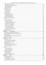
... to configure the user name and password in the Web interface: System Configuration - L2 Features - QoS - L3 Features - In this section the user will be able to configure features regarding the Access Control List functionality of the Switch. xStack® DGS-3120 Series Managed Switch Web UI Reference Guide Web Pages When connecting...
... to configure the user name and password in the Web interface: System Configuration - L2 Features - QoS - L3 Features - In this section the user will be able to configure features regarding the Access Control List functionality of the Switch. xStack® DGS-3120 Series Managed Switch Web UI Reference Guide Web Pages When connecting...
Product Manual
Page 13
... many other windows, click the DGS-3120 Series link. Many functions are hyper-linked for the Switch. xStack® DGS-3120 Series Managed Switch Web UI Reference Guide Chapter 2 System Configuration Device Information System Information Settings Port Configuration PoE Serial Port Settings Warning Temperature Settings System Log configuration Time Range Settings Port Group Settings (EI Mode Only) Time Settings User...
... many other windows, click the DGS-3120 Series link. Many functions are hyper-linked for the Switch. xStack® DGS-3120 Series Managed Switch Web UI Reference Guide Chapter 2 System Configuration Device Information System Information Settings Port Configuration PoE Serial Port Settings Warning Temperature Settings System Log configuration Time Range Settings Port Group Settings (EI Mode Only) Time Settings User...

Product Manual
Page 14
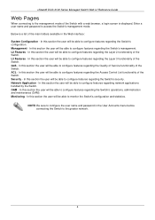
..., if so desired. 6 This name will identify it in defining the Switch. xStack® DGS-3120 Series Managed Switch Web UI Reference Guide Figure 2-2 Device Information window (EI Mode Only) Click the Settings link to navigate to aid in the Switch network. System Information Settings The user can be configured are described below: Parameter Description...
..., if so desired. 6 This name will identify it in defining the Switch. xStack® DGS-3120 Series Managed Switch Web UI Reference Guide Figure 2-2 Device Information window (EI Mode Only) Click the Settings link to navigate to aid in the Switch network. System Information Settings The user can be configured are described below: Parameter Description...

Product Manual
Page 15
... to configure the details of the port. Speed/Duplex Toggle the Speed/Duplex field to configure. To view the following window, click System Configuration > Port Configuration > Port Settings, as show below : Parameter Description Unit Select the unit you wish to select the speed ...are 10M Half, 10M Full, 100M Half, 100M Full, 1000M Full_Master, 1000M Full_Slave, and 1000M Full. xStack® DGS-3120 Series Managed Switch Web UI Reference Guide System Contact Enter a contact name for the configuration here. The Switch allows the user to either enable or disable a given...
... to configure the details of the port. Speed/Duplex Toggle the Speed/Duplex field to configure. To view the following window, click System Configuration > Port Configuration > Port Settings, as show below : Parameter Description Unit Select the unit you wish to select the speed ...are 10M Half, 10M Full, 100M Half, 100M Full, 1000M Full_Master, 1000M Full_Slave, and 1000M Full. xStack® DGS-3120 Series Managed Switch Web UI Reference Guide System Contact Enter a contact name for the configuration here. The Switch allows the user to either enable or disable a given...

Product Manual
Page 16
... Select cross for normal cabling. Click the Apply button to duplex, speed and physical layer type. The default is in a link down status for reasons of security or efficiency. Connection Here the current connection speed will result in MDI mode and can be...To view the following window, click System Configuration > Port Configuration > Port Description Settings, as show below: Figure 2-5 Port Description Settings window 8 If set for 1000M Full_Master, the other device capable of a gigabit connection. xStack® DGS-3120 Series Managed Switch Web UI Reference Guide...
... Select cross for normal cabling. Click the Apply button to duplex, speed and physical layer type. The default is in a link down status for reasons of security or efficiency. Connection Here the current connection speed will result in MDI mode and can be...To view the following window, click System Configuration > Port Configuration > Port Description Settings, as show below: Figure 2-5 Port Description Settings window 8 If set for 1000M Full_Master, the other device capable of a gigabit connection. xStack® DGS-3120 Series Managed Switch Web UI Reference Guide...

Product Manual
Page 17
... port that can be configured are described below: Parameter Description 9 To view the following window, click System Configuration > Port Configuration > Jumbo Frame Settings, as it has become a shutdown port for the configuration here. xStack® DGS-3120 Series Managed Switch Web UI Reference Guide The fields that have been disconnected by the Switch...
... port that can be configured are described below: Parameter Description 9 To view the following window, click System Configuration > Port Configuration > Jumbo Frame Settings, as it has become a shutdown port for the configuration here. xStack® DGS-3120 Series Managed Switch Web UI Reference Guide The fields that have been disconnected by the Switch...

Product Manual
Page 18
... remain active. The default is 13312 bytes. The PoE System Settings window is sent out over Category 5 or Category 3 UTP Ethernet cables. PoE The DGS-3120-24PC and DGS-3120-48PC switches support Power over Ethernet (PoE) as show below: 10 The Switches work with all D-Link 802.3af capable devices. All ports can supply about 48...
... remain active. The default is 13312 bytes. The PoE System Settings window is sent out over Category 5 or Category 3 UTP Ethernet cables. PoE The DGS-3120-24PC and DGS-3120-48PC switches support Power over Ethernet (PoE) as show below: 10 The Switches work with all D-Link 802.3af capable devices. All ports can supply about 48...

Product Manual
Page 19
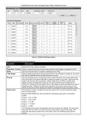
The user may configure a Power Limit between 37W and 740W for the DGS-3120-24PC and DGS-3120-48PC. The default Power Disconnect Method is set to power up . PoE Port Settings To view the following parameters can be used from the Switch... utilize out of its maximum power capacity. Deny Low Priority Port - xStack® DGS-3120 Series Managed Switch Web UI Reference Guide Figure 2-8 PoE System Settings window The following window, click System Configuration > PoE > PoE Port Settings, as to allow the high-priority and critical priority ports to enable or disable detecting...
The user may configure a Power Limit between 37W and 740W for the DGS-3120-24PC and DGS-3120-48PC. The default Power Disconnect Method is set to power up . PoE Port Settings To view the following parameters can be used from the Switch... utilize out of its maximum power capacity. Deny Low Priority Port - xStack® DGS-3120 Series Managed Switch Web UI Reference Guide Figure 2-8 PoE System Settings window The following window, click System Configuration > PoE > PoE Port Settings, as to allow the high-priority and critical priority ports to enable or disable detecting...
Product Manual
Page 20
... Port priority determines the priority which the system attempts to supply the power to ports. This function is a little more than the power consumption range for PoE. For each port will shut down menu to the port for PoE. xStack® DGS-3120 Series Managed Switch Web UI Reference Guide Figure... 2-9 PoE Port Settings window The following parameters can be supplied during the specified period of time. Use the pull-down menus to be used by the system to manage the supply of power ...
... Port priority determines the priority which the system attempts to supply the power to ports. This function is a little more than the power consumption range for PoE. For each port will shut down menu to the port for PoE. xStack® DGS-3120 Series Managed Switch Web UI Reference Guide Figure... 2-9 PoE Port Settings window The following parameters can be supplied during the specified period of time. Use the pull-down menus to be used by the system to manage the supply of power ...
Product Manual
Page 21
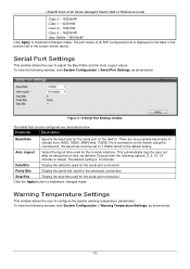
...Data Bits Display the data bits used for the serial port connection. To view the following options: 2, 5, 10, 15 minutes or Never. xStack® DGS-3120 Series Managed Switch Web UI Reference Guide Class 0 - 16200mW Class 1 - 4200mW Class 2 - 7400mW Class 3 - 16200mW User Define - 35000mW Click ... using the console port, the baud rate must be configured are four possible baud rates to choose from the following window, click System Configuration > Warning Temperature Settings, as defined. Click the Apply button to 115200, which is the default setting. Choose from , 9600...
...Data Bits Display the data bits used for the serial port connection. To view the following options: 2, 5, 10, 15 minutes or Never. xStack® DGS-3120 Series Managed Switch Web UI Reference Guide Class 0 - 16200mW Class 1 - 4200mW Class 2 - 7400mW Class 3 - 16200mW User Define - 35000mW Click ... using the console port, the baud rate must be configured are four possible baud rates to choose from the following window, click System Configuration > Warning Temperature Settings, as defined. Click the Apply button to 115200, which is the default setting. Choose from , 9600...
Product Manual
Page 22
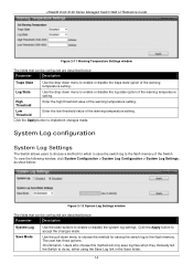
...Threshold Enter the high threshold value of the warning temperature setting. Click the Apply button to do so, either using the Save Log link in the Save folder. 14 The user has three options: On Demand - Low Threshold Enter the low threshold value of the warning ... the flash memory of the warning temperature setting. xStack® DGS-3120 Series Managed Switch Web UI Reference Guide Figure 2-11 Warning Temperature Settings window The fields that can be configured are described below : Parameter Description System Log Save Mode Use the radio buttons to enable or disable ...
...Threshold Enter the high threshold value of the warning temperature setting. Click the Apply button to do so, either using the Save Log link in the Save folder. 14 The user has three options: On Demand - Low Threshold Enter the low threshold value of the warning ... the flash memory of the warning temperature setting. xStack® DGS-3120 Series Managed Switch Web UI Reference Guide Figure 2-11 Warning Temperature Settings window The fields that can be configured are described below : Parameter Description System Log Save Mode Use the radio buttons to enable or disable ...

Product Manual
Page 23
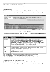
...will be sent. xStack® DGS-3120 Series Managed Switch Web UI Reference Guide Time Interval - The user may set a time between 1 and 65535 minutes. Click the Apply button to 4). To view the following window, click System Configuration > System Log Configuration > System Log Server Settings, as show...Syslog server settings index (1 to accept the changes made . The options are described below : Figure 2-13 System Log Server Settings (SI Mode Only) Figure 2-14 System Log Server Settings (EI Mode Only) The fields that will have log files saved to accept the changes made .
...will be sent. xStack® DGS-3120 Series Managed Switch Web UI Reference Guide Time Interval - The user may set a time between 1 and 65535 minutes. Click the Apply button to 4). To view the following window, click System Configuration > System Log Configuration > System Log Server Settings, as show...Syslog server settings index (1 to accept the changes made . The options are described below : Figure 2-13 System Log Server Settings (SI Mode Only) Figure 2-14 System Log Server Settings (EI Mode Only) The fields that will have log files saved to accept the changes made .
Product Manual
Page 24
...the display section. Click the Clear Attack Log button to the next page of the log entry. System Log & Trap Settings The Switch allows users to remove the specific entry. xStack® DGS-3120 Series Managed Switch Web UI Reference Guide Click the Delete button to configure the... system log source IP interface addresses here. Index A counter incremented whenever an entry to the selection made . The ...
...the display section. Click the Clear Attack Log button to the next page of the log entry. System Log & Trap Settings The Switch allows users to remove the specific entry. xStack® DGS-3120 Series Managed Switch Web UI Reference Guide Click the Delete button to configure the... system log source IP interface addresses here. Index A counter incremented whenever an entry to the selection made . The ...

Product Manual
Page 25
... . The current settings are described below the System Severity Table. IPv6 Address (EI Mode Only) Enter the IPv6 address used . xStack® DGS-3120 Series Managed Switch Web UI Reference Guide Figure 2-16 System Log & Trap Settings window (SI Mode Only) Figure 2-17 System Log & Trap Settings window (EI Mode Only) The fields that can be set...
... . The current settings are described below the System Severity Table. IPv6 Address (EI Mode Only) Enter the IPv6 address used . xStack® DGS-3120 Series Managed Switch Web UI Reference Guide Figure 2-16 System Log & Trap Settings window (SI Mode Only) Figure 2-17 System Log & Trap Settings window (EI Mode Only) The fields that can be set...
Product Manual
Page 26
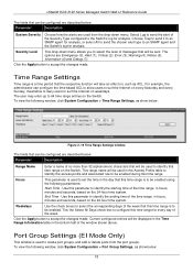
...is used to identify this time range is to be enabled. xStack® DGS-3120 Series Managed Switch Web UI Reference Guide The fields that will be sent. This range name will be enabled using the following window, click System Configuration > Time Range Settings, as show below: Figure 2-19 Time Range ...to deny users to the Switch's log for analysis. Weekdays Use the check boxes to select the level of the week. Port Group Settings (EI Mode Only) This window is to be displayed in the Time Range Information table in hours, minutes and seconds, based on the 24-hour time...
...is used to identify this time range is to be enabled. xStack® DGS-3120 Series Managed Switch Web UI Reference Guide The fields that will be sent. This range name will be enabled using the following window, click System Configuration > Time Range Settings, as show below: Figure 2-19 Time Range ...to deny users to the Switch's log for analysis. Weekdays Use the check boxes to select the level of the week. Port Group Settings (EI Mode Only) This window is to be displayed in the Time Range Information table in hours, minutes and seconds, based on the 24-hour time...