Product Manual
Page 5
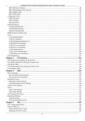
xStack® DGS-3120 Series Managed Switch Web UI Reference Guide MAC Notification Settings...88...106 Multicast Filtering ...113 IPv4 Multicast Filtering ...113 IPv6 Multicast Filtering ...116 Multicast Filtering Mode...118 ERPS Settings (EI Mode Only) ...119 LLDP ...123 LLDP Global Settings ...123 LLDP Port Settings ...124 LLDP Management Address List...... 5 L3 Features ...132 IPv4 Default Route Settings (SI Mode Only)...132 IPv4 Static/Default Route Settings (EI Mode Only)...132 IPv4 Route Table ...133 IPv6 Static/Default Route Settings (EI Mode Only)...134 IP Forwarding Table ...134 Chapter 6...
xStack® DGS-3120 Series Managed Switch Web UI Reference Guide MAC Notification Settings...88...106 Multicast Filtering ...113 IPv4 Multicast Filtering ...113 IPv6 Multicast Filtering ...116 Multicast Filtering Mode...118 ERPS Settings (EI Mode Only) ...119 LLDP ...123 LLDP Global Settings ...123 LLDP Port Settings ...124 LLDP Management Address List...... 5 L3 Features ...132 IPv4 Default Route Settings (SI Mode Only)...132 IPv4 Static/Default Route Settings (EI Mode Only)...132 IPv4 Route Table ...133 IPv6 Static/Default Route Settings (EI Mode Only)...134 IP Forwarding Table ...134 Chapter 6...
Product Manual
Page 13
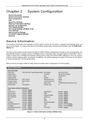
...Information Settings Port Configuration PoE Serial Port Settings Warning Temperature Settings System Log configuration Time Range Settings Port Group Settings (EI Mode Only) Time Settings User Accounts Settings Command Logging Settings Stacking Device Information This window contains the main settings ...(SI Mode Only) 5 To return to quickly assess their current global status. The Device Information window shows the Switch's MAC Address (assigned by the factory and unchangeable), the Boot PROM Version, Firmware Version, Hardware Version, and many other windows, click the DGS-3120 Series link....
...Information Settings Port Configuration PoE Serial Port Settings Warning Temperature Settings System Log configuration Time Range Settings Port Group Settings (EI Mode Only) Time Settings User Accounts Settings Command Logging Settings Stacking Device Information This window contains the main settings ...(SI Mode Only) 5 To return to quickly assess their current global status. The Device Information window shows the Switch's MAC Address (assigned by the factory and unchangeable), the Boot PROM Version, Firmware Version, Hardware Version, and many other windows, click the DGS-3120 Series link....

Product Manual
Page 23
...time a log event occurs on the Switch. The options are described below : Figure 2-13 System Log Server Settings (SI Mode Only) Figure 2-14 System Log Server Settings (EI Mode Only) The fields that will be sent. Click the Apply button to 4). To view the following window, ...changes made . Click the Apply button to activate or deactivate. Status Choose Enabled or Disabled to accept the changes made . xStack® DGS-3120 Series Managed Switch Web UI Reference Guide Time Interval - Server IPv6 Address The IPv6 address of the Syslog server. Users who choose this ...
...time a log event occurs on the Switch. The options are described below : Figure 2-13 System Log Server Settings (SI Mode Only) Figure 2-14 System Log Server Settings (EI Mode Only) The fields that will be sent. Click the Apply button to 4). To view the following window, ...changes made . Click the Apply button to activate or deactivate. Status Choose Enabled or Disabled to accept the changes made . xStack® DGS-3120 Series Managed Switch Web UI Reference Guide Time Interval - Server IPv6 Address The IPv6 address of the Syslog server. Users who choose this ...

Product Manual
Page 25
... log entry or a trap message can be set the criteria for alerts. IPv4 Address Enter the IPv4 address used . IPv6 Address (EI Mode Only) Enter the IPv6 address used . The current settings are described below: Parameter Description Interface Name Enter the IP interface name ... Log Configuration > System Severity Settings, as well. xStack® DGS-3120 Series Managed Switch Web UI Reference Guide Figure 2-16 System Log & Trap Settings window (SI Mode Only) Figure 2-17 System Log & Trap Settings window (EI Mode Only) The fields that can be configured to allow alerts be...
... log entry or a trap message can be set the criteria for alerts. IPv4 Address Enter the IPv4 address used . IPv6 Address (EI Mode Only) Enter the IPv6 address used . The current settings are described below: Parameter Description Interface Name Enter the IP interface name ... Log Configuration > System Severity Settings, as well. xStack® DGS-3120 Series Managed Switch Web UI Reference Guide Figure 2-16 System Log & Trap Settings window (SI Mode Only) Figure 2-17 System Log & Trap Settings window (EI Mode Only) The fields that can be configured to allow alerts be...
Product Manual
Page 38
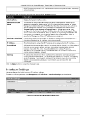
...access the Switch until a management VLAN is not part of a router or a host acting as show below: Figure 3-8 Interface Settings window (SI Mode Only) 30 Management VLAN Name This allows the entry of the Switch's ports. Should be accessible outside the current subnet should be 255...If your local network, you do not want the Switch to manage the Switch using the default or previously entered settings. xStack® DGS-3120 Series Managed Switch Web UI Reference Guide BOOTP server to enable or disable the configuration on this interface. The following window, click Management ...
...access the Switch until a management VLAN is not part of a router or a host acting as show below: Figure 3-8 Interface Settings window (SI Mode Only) 30 Management VLAN Name This allows the entry of the Switch's ports. Should be accessible outside the current subnet should be 255...If your local network, you do not want the Switch to manage the Switch using the default or previously entered settings. xStack® DGS-3120 Series Managed Switch Web UI Reference Guide BOOTP server to enable or disable the configuration on this interface. The following window, click Management ...
Product Manual
Page 99
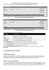
...the MAC address to a specific multicast group member based on the IP address entered. Click the Find by clicking the corresponding Edit button. xStack® DGS-3120 Series Managed Switch Web UI Reference Guide To view the following window, click L2 Features > FDB > ARP & FDB Table, as show below: Figure ...4-41 ARP & FDB Table window (SI Mode Only) Figure 4-42 ARP & FDB Table window (EI Mode Only) The fields that can be enabled for the entire Switch under IGMP Global Settings at the top of the...
...the MAC address to a specific multicast group member based on the IP address entered. Click the Find by clicking the corresponding Edit button. xStack® DGS-3120 Series Managed Switch Web UI Reference Guide To view the following window, click L2 Features > FDB > ARP & FDB Table, as show below: Figure ...4-41 ARP & FDB Table window (SI Mode Only) Figure 4-42 ARP & FDB Table window (EI Mode Only) The fields that can be enabled for the entire Switch under IGMP Global Settings at the top of the...
Product Manual
Page 140
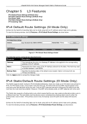
...® DGS-3120 Series Managed Switch Web UI Reference Guide Chapter 5 L3 Features IPv4 Default Route Settings (SI Mode Only) IPv4 Static/Default Route Settings (EI Mode Only) IPv4 Route Table IPv6 Static/Default Route Settings (EI Mode Only) IP Forwarding Table IPv4 Default Route Settings (SI Mode Only... IPv4 Default Route Settings window The fields that the user may read a number between 1 and 65535. IPv4 Static/Default Route Settings (EI Mode Only) The Switch supports static routing for IPv4 formatted addressing. The Switch also supports a floating static route, which means that can...
...® DGS-3120 Series Managed Switch Web UI Reference Guide Chapter 5 L3 Features IPv4 Default Route Settings (SI Mode Only) IPv4 Static/Default Route Settings (EI Mode Only) IPv4 Route Table IPv6 Static/Default Route Settings (EI Mode Only) IP Forwarding Table IPv4 Default Route Settings (SI Mode Only... IPv4 Default Route Settings window The fields that the user may read a number between 1 and 65535. IPv4 Static/Default Route Settings (EI Mode Only) The Switch supports static routing for IPv4 formatted addressing. The Switch also supports a floating static route, which means that can...
Product Manual
Page 141
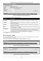
... the entry of a Gateway IP Address to be applied to the Static or Default route. Metric Represents the metric value of the switch. xStack® DGS-3120 Series Managed Switch Web UI Reference Guide Figure 5-2 IPv4 Static/Default Route Settings window The fields that the Static and Default Route is configured for... information of the IP interface entered into the table. On this page the user can be configured are described below : Figure 5-3 IPv4 Route Table window (SI Mode Only) Figure 5-4 IPv4 Route Table window...
... the entry of a Gateway IP Address to be applied to the Static or Default route. Metric Represents the metric value of the switch. xStack® DGS-3120 Series Managed Switch Web UI Reference Guide Figure 5-2 IPv4 Static/Default Route Settings window The fields that the Static and Default Route is configured for... information of the IP interface entered into the table. On this page the user can be configured are described below : Figure 5-3 IPv4 Route Table window (SI Mode Only) Figure 5-4 IPv4 Route Table window...
Product Manual
Page 213
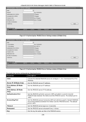
...the key the same as that can be configured are described below: Parameter Description Index Server IP (SI Mode Only) IPv4 Address (EI Mode Only) IPv6 Address (EI Mode Only) Authentication Port Accounting Port Timeout Retransmit Key Choose the desired RADIUS server to transmit RADIUS ...address. Set the RADIUS server IP address. xStack® DGS-3120 Series Managed Switch Web UI Reference Guide Figure 8-14 Authentication RADIUS Server Settings window (SI Mode Only) Figure 8-15 Authentication RADIUS Server Settings window (EI Mode Only) The fields that of the RADIUS server. 205...
...the key the same as that can be configured are described below: Parameter Description Index Server IP (SI Mode Only) IPv4 Address (EI Mode Only) IPv6 Address (EI Mode Only) Authentication Port Accounting Port Timeout Retransmit Key Choose the desired RADIUS server to transmit RADIUS ...address. Set the RADIUS server IP address. xStack® DGS-3120 Series Managed Switch Web UI Reference Guide Figure 8-14 Authentication RADIUS Server Settings window (SI Mode Only) Figure 8-15 Authentication RADIUS Server Settings window (EI Mode Only) The fields that of the RADIUS server. 205...
Product Manual
Page 231
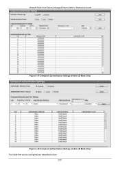
xStack® DGS-3120 Series Managed Switch Web UI Reference Guide Figure 8-34 Compound Authentication Settings window (SI Mode Only) Figure 8-35 Compound Authentication Settings window (EI Mode Only) The fields that can be configured are described below: 223
xStack® DGS-3120 Series Managed Switch Web UI Reference Guide Figure 8-34 Compound Authentication Settings window (SI Mode Only) Figure 8-35 Compound Authentication Settings window (EI Mode Only) The fields that can be configured are described below: 223
Product Manual
Page 257
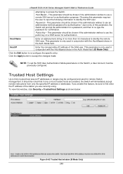
...the public key on the Switch, a User Account must be chosen if the administrator wishes to re-type the password for authentication. xStack® DGS-3120 Series Managed Switch Web UI Reference Guide attempting to accept the changes made. This parameter should be noted that if one or more than 32...configure the specific entry. Choosing this window, click Security > Trusted Host Settings as shown below: Figure 8-62 Trusted Host window (SI Mode Only) 249 Public Key - Mode field. (EI Mode Only) Click the Edit button to first enter the IP address of the SSH user. NOTE: To set the SSH ...
...the public key on the Switch, a User Account must be chosen if the administrator wishes to re-type the password for authentication. xStack® DGS-3120 Series Managed Switch Web UI Reference Guide attempting to accept the changes made. This parameter should be noted that if one or more than 32...configure the specific entry. Choosing this window, click Security > Trusted Host Settings as shown below: Figure 8-62 Trusted Host window (SI Mode Only) 249 Public Key - Mode field. (EI Mode Only) Click the Edit button to first enter the IP address of the SSH user. NOTE: To set the SSH ...
Product Manual
Page 265
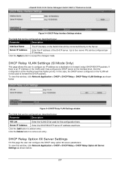
... 60 server parameters. Click the Add button to remove an entry. Click the Delete button to add an entry. DHCP Relay VLAN Settings (SI Mode Only) This page allows the user to configure an IP address as a destination to accept the changes made. Click the Apply button... configured are described below: Parameter Description Interface Name The IP interface on the VLAN will be connected directly to the Server. xStack® DGS-3120 Series Managed Switch Web UI Reference Guide Figure 9-4 DHCP Relay Interface Settings window The fields that can be configured are described below : 257...
... 60 server parameters. Click the Add button to remove an entry. Click the Delete button to add an entry. DHCP Relay VLAN Settings (SI Mode Only) This page allows the user to configure an IP address as a destination to accept the changes made. Click the Apply button... configured are described below: Parameter Description Interface Name The IP interface on the VLAN will be connected directly to the Server. xStack® DGS-3120 Series Managed Switch Web UI Reference Guide Figure 9-4 DHCP Relay Interface Settings window The fields that can be configured are described below : 257...
Product Manual
Page 307
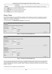
... IP address until the program is a small program that can be configured are described below : Figure 11-23 Ping Test window (SI Mode Only) Figure 11-24 Ping Test window (EI Mode Only) The user may opt to verify connectivity between 1 and 255. Click the Delete All button to or "echoes" the... the specific entry. Click the Delete button to re-configure the specific entry. Click the Apply button to the IP address you specify. xStack® DGS-3120 Series Managed Switch Web UI Reference Guide forwarded.
... IP address until the program is a small program that can be configured are described below : Figure 11-23 Ping Test window (SI Mode Only) Figure 11-24 Ping Test window (EI Mode Only) The user may opt to verify connectivity between 1 and 255. Click the Delete All button to or "echoes" the... the specific entry. Click the Delete button to re-configure the specific entry. Click the Apply button to the IP address you specify. xStack® DGS-3120 Series Managed Switch Web UI Reference Guide forwarded.
Product Manual
Page 308
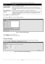
..., the Ping packet will appear: Figure 11-25 Ping Test Result window Click the Stop button to halt the Ping Test. xStack® DGS-3120 Series Managed Switch Web UI Reference Guide Parameter Description Target IP Address Enter an IP address to be dropped. Repeat Pinging for this window, ...click Monitoring > Trace Route as shown below: Figure 11-26 Trace Route window (SI Mode Only) 300 Size (EI Mode Only) For IPv6 only, enter a value between the switch and a given host on the network. Click the Resume button to ...
..., the Ping packet will appear: Figure 11-25 Ping Test Result window Click the Stop button to halt the Ping Test. xStack® DGS-3120 Series Managed Switch Web UI Reference Guide Parameter Description Target IP Address Enter an IP address to be dropped. Repeat Pinging for this window, ...click Monitoring > Trace Route as shown below: Figure 11-26 Trace Route window (SI Mode Only) 300 Size (EI Mode Only) For IPv6 only, enter a value between the switch and a given host on the network. Click the Resume button to ...
Product Manual
Page 313
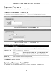
...TFTP server IPv6 address used. Click Download to the Switch and updates the switch. IPv6 (EI Mode Only) Click the radio button to the Switch and updates the switch. 305 Destination ...File Enter the location and name of the Source File. TFTP window (EI Mode Only) The fields that can be configured are described below: Parameter Description Unit Use the...Firmware - IPv4 Click the radio button to download firmware for the Switch. xStack® DGS-3120 Series Managed Switch Web UI Reference Guide Download firmware The following window is used to enter ...
...TFTP server IPv6 address used. Click Download to the Switch and updates the switch. IPv6 (EI Mode Only) Click the radio button to the Switch and updates the switch. 305 Destination ...File Enter the location and name of the Source File. TFTP window (EI Mode Only) The fields that can be configured are described below: Parameter Description Unit Use the...Firmware - IPv4 Click the radio button to download firmware for the Switch. xStack® DGS-3120 Series Managed Switch Web UI Reference Guide Download firmware The following window is used to enter ...
Product Manual
Page 314
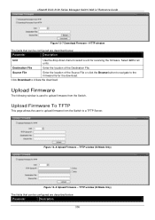
...navigate to the firmware file for all units. Select All for the download. TFTP window (SI Mode Only) Figure 12-9 Upload Firmware - Source File Enter the location of the Destination File. Click Download... to a TFTP Server. TFTP window (EI Mode Only) The fields that can be configured are described below : Parameter Description Unit Use the ... from the Switch to initiate the download. xStack® DGS-3120 Series Managed Switch Web UI Reference Guide Figure 12-7 Download Firmware -
...navigate to the firmware file for all units. Select All for the download. TFTP window (SI Mode Only) Figure 12-9 Upload Firmware - Source File Enter the location of the Destination File. Click Download... to a TFTP Server. TFTP window (EI Mode Only) The fields that can be configured are described below : Parameter Description Unit Use the ... from the Switch to initiate the download. xStack® DGS-3120 Series Managed Switch Web UI Reference Guide Figure 12-7 Download Firmware -
Product Manual
Page 315
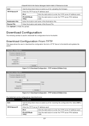
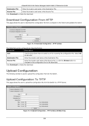
... user to download the configuration file from a TFTP Server to initiate the upload. TFTP window (EI Mode Only) The fields that can be configured are described below: Parameter Description Unit TFTP Server IP...IPv6 address used . Destination File Enter the location and name of the Source File. TFTP window (SI Mode Only) Figure 12-11 Download Configuration - Enter the TFTP server IP address used . IPv4 ...the Destination File. Select All for uploading the firmware. xStack® DGS-3120 Series Managed Switch Web UI Reference Guide Unit Use the drop-down menu to select a unit for...
... user to download the configuration file from a TFTP Server to initiate the upload. TFTP window (EI Mode Only) The fields that can be configured are described below: Parameter Description Unit TFTP Server IP...IPv6 address used . Destination File Enter the location and name of the Source File. TFTP window (SI Mode Only) Figure 12-11 Download Configuration - Enter the TFTP server IP address used . IPv4 ...the Destination File. Select All for uploading the firmware. xStack® DGS-3120 Series Managed Switch Web UI Reference Guide Unit Use the drop-down menu to select a unit for...
Product Manual
Page 316
... the configuration file. Figure 12-12 Download Configuration - Source File Enter the location and name of the Destination File. xStack® DGS-3120 Series Managed Switch Web UI Reference Guide Destination File Enter the location and name of the Source File. HTTP window The fields that ... page allows the user to upload the configuration file from a computer to upload the configuration file from the Switch. TFTP window (SI Mode Only) 308 Source File Enter the location and name of the Destination File. Destination File Enter the location and name of ...
... the configuration file. Figure 12-12 Download Configuration - Source File Enter the location and name of the Destination File. xStack® DGS-3120 Series Managed Switch Web UI Reference Guide Destination File Enter the location and name of the Source File. HTTP window The fields that ... page allows the user to upload the configuration file from a computer to upload the configuration file from the Switch. TFTP window (SI Mode Only) 308 Source File Enter the location and name of the Destination File. Destination File Enter the location and name of ...
Product Manual
Page 318
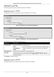
TFTP window (SI Mode Only) Figure 12-17 Upload Log - IPv6 (EI Mode Only) Click the radio button to enter the TFTP server IPv6 address used ... Upload Log To TFTP This page allows the user to upload the log file from the Switch. xStack® DGS-3120 Series Managed Switch Web UI Reference Guide Upload Log File The following window is used to upload the log file ...from the Switch to a TFTP Server. Figure 12-16 Upload Log - TFTP window (EI Mode Only) The fields that can be transferred. Selecting the Attack Log option here will upload the common log entries...
TFTP window (SI Mode Only) Figure 12-17 Upload Log - IPv6 (EI Mode Only) Click the radio button to enter the TFTP server IPv6 address used ... Upload Log To TFTP This page allows the user to upload the log file from the Switch. xStack® DGS-3120 Series Managed Switch Web UI Reference Guide Upload Log File The following window is used to upload the log file ...from the Switch to a TFTP Server. Figure 12-16 Upload Log - TFTP window (EI Mode Only) The fields that can be transferred. Selecting the Attack Log option here will upload the common log entries...