Product Manual
Page 2
... Contents D-Link Web Smart Switch User Manual Table of Contents Table of Contents ...i About This Guide...1 Online Resources...1 Terms/Usage...1 Copy Right and Trademarks ...1 Hardware Installation ...2 Step1: Unpacking...2 Step2: Switch Installation...2 Desktop or Shelf Installation...2 Rack Installation ...2 Step 3 - Plugging in the AC Power Cord...3 Power Failure ...3 Getting Started...4 Management Options...4 Using Web-based Management Utility...4 Supported Web Browsers ...4 Connecting...
... Contents D-Link Web Smart Switch User Manual Table of Contents Table of Contents ...i About This Guide...1 Online Resources...1 Terms/Usage...1 Copy Right and Trademarks ...1 Hardware Installation ...2 Step1: Unpacking...2 Step2: Switch Installation...2 Desktop or Shelf Installation...2 Rack Installation ...2 Step 3 - Plugging in the AC Power Cord...3 Power Failure ...3 Getting Started...4 Management Options...4 Using Web-based Management Utility...4 Supported Web Browsers ...4 Connecting...
Product Manual
Page 3
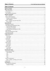
...) > PoE System Settings (Only for DGS-1224TP 35 Power over Ethernet (PoE) ...1 Appendix B - Technical Specifications ...3 Hardware Specifications ...3 Key Components / Performance ...3 Port Functions ...3 Physical & Environment ...3 Emission (EMI) Certifications ...3 Safety Certifications...3 Features ...3 L2 Features ...3 VLAN ...3 ii Table of Contents D-Link Web Smart Switch User Manual SNMP Settings ...20 System Settings...21 Identifying the Web-based Management Utility 22 Tool Menu...
...) > PoE System Settings (Only for DGS-1224TP 35 Power over Ethernet (PoE) ...1 Appendix B - Technical Specifications ...3 Hardware Specifications ...3 Key Components / Performance ...3 Port Functions ...3 Physical & Environment ...3 Emission (EMI) Certifications ...3 Safety Certifications...3 Features ...3 L2 Features ...3 VLAN ...3 ii Table of Contents D-Link Web Smart Switch User Manual SNMP Settings ...20 System Settings...21 Identifying the Web-based Management Utility 22 Tool Menu...

Product Manual
Page 4
Table of Contents D-Link Web Smart Switch User Manual QoS (Quality of Service)...3 Security...3 Management...3 iii
Table of Contents D-Link Web Smart Switch User Manual QoS (Quality of Service)...3 Security...3 Management...3 iii
Product Manual
Page 5
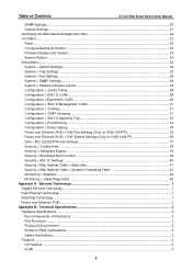
... have purchased may be used in any proprietary interest in this guide, the term "Switch" (first letter is mainly divided into four parts: 1. About This Guide D-Link Web Smart Switch User Manual About This Guide This guide provides instructions to install D-Link Gigabit Ethernet Web Smart Switches DGS1216T/24T/24TP/48T, how to use the SmartConsole Utility, and to the central...
... have purchased may be used in any proprietary interest in this guide, the term "Switch" (first letter is mainly divided into four parts: 1. About This Guide D-Link Web Smart Switch User Manual About This Guide This guide provides instructions to install D-Link Gigabit Ethernet Web Smart Switches DGS1216T/24T/24TP/48T, how to use the SmartConsole Utility, and to the central...
Product Manual
Page 6
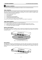
... and undamaged. To install, attach the mounting brackets to the Switch 2 Figure 2 - One D-Link Web-Smart Switch One AC power cord Four rubber feet Screws and two mounting brackets One Multi-lingual Getting Started Guide User's Guide CD with the device must be placed in the User Manual to the AC power connector. Attach the adhesive rubber pads...
... and undamaged. To install, attach the mounting brackets to the Switch 2 Figure 2 - One D-Link Web-Smart Switch One AC power cord Four rubber feet Screws and two mounting brackets One Multi-lingual Getting Started Guide User's Guide CD with the device must be placed in the User Manual to the AC power connector. Attach the adhesive rubber pads...
Product Manual
Page 7
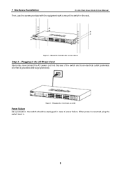
Figure 4 -Plugging the switch into the rear of power failure. Mount the Switch in case of the switch and to mount the switch in the rack. Plugging in . 3 When power is grounded and surge protected). Figure 3 - 1 Hardware Installation D-Link Web Smart Switch User Manual Then, use the screws provided with the equipment rack to an electrical outlet (preferably one that is resumed, plug the switch back in the AC Power Cord Users may now connect the AC power cord into an outlet Power Failure As a precaution, the switch should be unplugged in the rack or chassis Step 3 -
Figure 4 -Plugging the switch into the rear of power failure. Mount the Switch in case of the switch and to mount the switch in the rack. Plugging in . 3 When power is grounded and surge protected). Figure 3 - 1 Hardware Installation D-Link Web Smart Switch User Manual Then, use the screws provided with the equipment rack to an electrical outlet (preferably one that is resumed, plug the switch back in the AC Power Cord Users may now connect the AC power cord into an outlet Power Failure As a precaution, the switch should be unplugged in the rack or chassis Step 3 -
Product Manual
Page 8
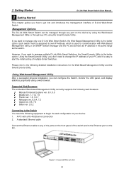
.... Please refer to the following equipment to begin the web configuration of D-Link Web-Smart Switch. 2 Getting Started D-Link Web Smart Switch User Manual 2 Getting Started This chapter guides you want to manage multiple D-Link Web Smart Switches, the SmartConsole Utility is the better option. Management Options The D-Link Web Smart Switch can configure the Switch, monitor the LED panel, and display statistics graphically using the SmartConsole Utility. If you...
.... Please refer to the following equipment to begin the web configuration of D-Link Web-Smart Switch. 2 Getting Started D-Link Web Smart Switch User Manual 2 Getting Started This chapter guides you want to manage multiple D-Link Web Smart Switches, the SmartConsole Utility is the better option. Management Options The D-Link Web Smart Switch can configure the Switch, monitor the LED panel, and display statistics graphically using the SmartConsole Utility. If you...
Product Manual
Page 9
... detail configurations. This tool is only for the installation of SmartConsole Utility, one is through the SmartConsole Utility. 2 Getting Started D-Link Web Smart Switch User Manual Login Web-based Management Utility In order to login and configure the switch via an Ethernet connection, the PC must have an IP address of 192.168.0.x (where x is a number between 2 and...
... detail configurations. This tool is only for the installation of SmartConsole Utility, one is through the SmartConsole Utility. 2 Getting Started D-Link Web Smart Switch User Manual Login Web-based Management Utility In order to login and configure the switch via an Ethernet connection, the PC must have an IP address of 192.168.0.x (where x is a number between 2 and...
Product Manual
Page 10
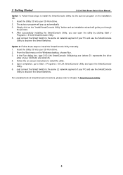
Simply click on the installation CD. 1. 2 Getting Started D-Link Web Smart Switch User Manual Option 1: Follow these steps to install the SmartConsole Utility manually. 1. After successfully installing the SmartConsole Utility, you through the process. 4. From the Start menu on -screen instructions to...into your CD-Rom) and click OK. 4. Option 2: Follow these steps to discover the Smart Switches. Follow the on the Windows desktop, choose Run. 3. In the Run dialog box, type D:\D-Link SmartConsole Utility\setup.exe (where D:\ represents the drive letter of your PC and use the...
Simply click on the installation CD. 1. 2 Getting Started D-Link Web Smart Switch User Manual Option 1: Follow these steps to install the SmartConsole Utility manually. 1. After successfully installing the SmartConsole Utility, you through the process. 4. From the Start menu on -screen instructions to...into your CD-Rom) and click OK. 4. Option 2: Follow these steps to discover the Smart Switches. Follow the on the Windows desktop, choose Run. 3. In the Run dialog box, type D:\D-Link SmartConsole Utility\setup.exe (where D:\ represents the drive letter of your PC and use the...
Product Manual
Page 11
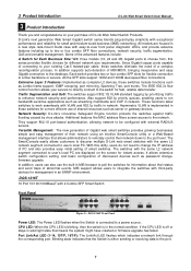
...for different network size requirements. MIB support allows users to the port. 7 Port Link/Act LED (1-14, 15T/F, 16T/F): The Link/Act LED flashes which indicates a network link through the corresponding port. DGS-1216T 16 Port 10/100/1000BaseT with third-... rack-mount metal case with external RADIUS servers. 3 Product Introduction D-Link Web Smart Switch User Manual 3 Product Introduction Thank you and congratulations on the screen for instant access. D-Link's next generation Web Smart Gigabit switch series blends plug-and-play simplicity with the same L2 network segment ...
...for different network size requirements. MIB support allows users to the port. 7 Port Link/Act LED (1-14, 15T/F, 16T/F): The Link/Act LED flashes which indicates a network link through the corresponding port. DGS-1216T 16 Port 10/100/1000BaseT with third-... rack-mount metal case with external RADIUS servers. 3 Product Introduction D-Link Web Smart Switch User Manual 3 Product Introduction Thank you and congratulations on the screen for instant access. D-Link's next generation Web Smart Gigabit switch series blends plug-and-play simplicity with the same L2 network segment ...
Product Manual
Page 12
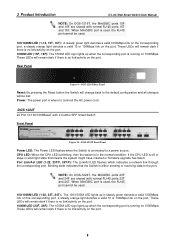
... - Power: The power port is connected to the port. These LEDs will remain dark if there is running on the port. NOTE: On DGS-1224T, the MiniGBIC ports 23F and 24F are shared with normal RJ-45 ports 15T and 16T. These LEDs will be used , the RJ-45 ..., 24F): The 1000M LED sign lights up in steady green denotes a valid 1000Mbps link on the corresponding port, a steady orange light denotes a valid 10 or 100Mbps link on the port. 8 3 Product Introduction D-Link Web Smart Switch User Manual NOTE: On DGS-1216T, the MiniGBIC ports 15F and 16F are shared with normal RJ-45 ports 23T...
... - Power: The power port is connected to the port. These LEDs will remain dark if there is running on the port. NOTE: On DGS-1224T, the MiniGBIC ports 23F and 24F are shared with normal RJ-45 ports 15T and 16T. These LEDs will be used , the RJ-45 ..., 24F): The 1000M LED sign lights up in steady green denotes a valid 1000Mbps link on the corresponding port, a steady orange light denotes a valid 10 or 100Mbps link on the port. 8 3 Product Introduction D-Link Web Smart Switch User Manual NOTE: On DGS-1216T, the MiniGBIC ports 15F and 16F are shared with normal RJ-45 ports 23T...
Product Manual
Page 13
... when the Switch is off indicates all changes will change back to a power source. If the CPU LED is connected to the default configuration and all fans work fine and the red light indicates that means the system might have crashed or firmware upgrade has failed. 3 Product Introduction Rear Panel D-Link Web Smart Switch User Manual Figure...
... when the Switch is off indicates all changes will change back to a power source. If the CPU LED is connected to the default configuration and all fans work fine and the red light indicates that means the system might have crashed or firmware upgrade has failed. 3 Product Introduction Rear Panel D-Link Web Smart Switch User Manual Figure...
Product Manual
Page 14
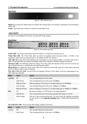
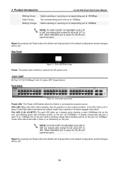
...Link Web Smart Switch User Manual Blinking Green Solid Orange Blinking Orange Data is sending or receiving on corresponding port at 1000Mbps The corresponding port is link up in steady green denotes a valid 1000Mbps link on the port, and blinking green light indicates activity on the port (at 1000Mbps). A steady orange light denotes a valid 10 or 100Mbps link...shared with normal RJ-45 ports 45T to 48T. DGS-1248T 48 Port 10/100/1000BaseT with 4 Combo SFP Smart Switch Front Panel Figure 14 - If the CPU LED is where to a power source. DGS-1224TP Rear Panel Power: The power port is off...
...Link Web Smart Switch User Manual Blinking Green Solid Orange Blinking Orange Data is sending or receiving on corresponding port at 1000Mbps The corresponding port is link up in steady green denotes a valid 1000Mbps link on the port, and blinking green light indicates activity on the port (at 1000Mbps). A steady orange light denotes a valid 10 or 100Mbps link...shared with normal RJ-45 ports 45T to 48T. DGS-1248T 48 Port 10/100/1000BaseT with 4 Combo SFP Smart Switch Front Panel Figure 14 - If the CPU LED is where to a power source. DGS-1224TP Rear Panel Power: The power port is off...

Product Manual
Page 15
3 Product Introduction Rear Panel D-Link Web Smart Switch User Manual Figure 15 - DGS-1248T Rear Panel Power: The power port is where to connect the AC power cord. 11
3 Product Introduction Rear Panel D-Link Web Smart Switch User Manual Figure 15 - DGS-1248T Rear Panel Power: The power port is where to connect the AC power cord. 11
Product Manual
Page 16
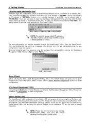
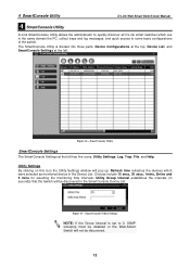
...be discovered. 12 Figure 17 - The SmartConsole Utility is set to 0, IGMP snooping must be disabled or the Web-Smart Switch will not be discovered in the SmartConsole Device List. SmartConsole Utility Settings NOTE: If the Group Interval is divided ... has five icons, Utility Settings, Log, Trap, File, and Help. 4 SmartConsole Utility D-Link Web Smart Switch User Manual 4 SmartConsole Utility D-Link SmartConsole Utility allows the administrator to quickly discover all D-Link smart switches which were selected as monitored device in the Device List. Choices include 15 secs, 30 secs...
...be discovered. 12 Figure 17 - The SmartConsole Utility is set to 0, IGMP snooping must be disabled or the Web-Smart Switch will not be discovered in the SmartConsole Device List. SmartConsole Utility Settings NOTE: If the Group Interval is divided ... has five icons, Utility Settings, Log, Trap, File, and Help. 4 SmartConsole Utility D-Link Web Smart Switch User Manual 4 SmartConsole Utility D-Link SmartConsole Utility allows the administrator to quickly discover all D-Link smart switches which were selected as monitored device in the Device List. Choices include 15 secs, 30 secs...
Product Manual
Page 17
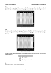
4 SmartConsole Utility D-Link Web Smart Switch User Manual Log By clicking on this icon the Log window will pop up . SmartConsole Log Trap By clicking on this trap message. Figure 19 - Click View ...
4 SmartConsole Utility D-Link Web Smart Switch User Manual Log By clicking on this icon the Log window will pop up . SmartConsole Log Trap By clicking on this trap message. Figure 19 - Click View ...
Product Manual
Page 18
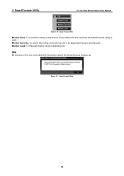
SmartConsole File Monitor Save: To record the setting of the Device List in an appointed filename and file path. Help By clicking on this icon a window with information about the SmartConsole will pop up. Monitor Save As: To record the setting of the Device List as default for the next time the SmartConsole Utility is used. Monitor Load: To manually load a Device List setting file. Figure 21 - SmartConsole Help 14 4 SmartConsole Utility D-Link Web Smart Switch User Manual Figure 20 -
SmartConsole File Monitor Save: To record the setting of the Device List in an appointed filename and file path. Help By clicking on this icon a window with information about the SmartConsole will pop up. Monitor Save As: To record the setting of the Device List as default for the next time the SmartConsole Utility is used. Monitor Load: To manually load a Device List setting file. Figure 21 - SmartConsole Help 14 4 SmartConsole Utility D-Link Web Smart Switch User Manual Figure 20 -

Product Manual
Page 19
... for the Device List. SmartConsole Device Settings 15 Here you can configure the Product Name, IP Address, Gateway, Subnet Mask, System Name, Location, Trap IP, Switch Group Interval, and DHCP Setting of the Switch. 4 SmartConsole Utility D-Link Web Smart Switch User Manual Device Configurations The Device Configurations in Confirm Password then click OK Figure 22 - Device Settings Select...
... for the Device List. SmartConsole Device Settings 15 Here you can configure the Product Name, IP Address, Gateway, Subnet Mask, System Name, Location, Trap IP, Switch Group Interval, and DHCP Setting of the Switch. 4 SmartConsole Utility D-Link Web Smart Switch User Manual Device Configurations The Device Configurations in Confirm Password then click OK Figure 22 - Device Settings Select...
Product Manual
Page 20
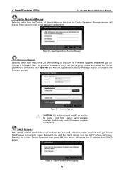
.... Choose a Firmware Path (or you 're going to complete the firmware upgrade Figure 24 - DHCP Refresh: If the DHCP enabled switch in Device List shows the default IP, which means the device doesn't get IP from device until upgrade complete. Figure 25...enter a new password and confirm. Entering the correct Device Password then press OK, the device will popup. 4 SmartConsole Utility D-Link Web Smart Switch User Manual Device Password Manager Select a switch from the Device List, then clicking on this icon the Firmware Upgrade window will pop up to use then input the correct password...
.... Choose a Firmware Path (or you 're going to complete the firmware upgrade Figure 24 - DHCP Refresh: If the DHCP enabled switch in Device List shows the default IP, which means the device doesn't get IP from device until upgrade complete. Figure 25...enter a new password and confirm. Entering the correct Device Password then press OK, the device will popup. 4 SmartConsole Utility D-Link Web Smart Switch User Manual Device Password Manager Select a switch from the Device List, then clicking on this icon the Firmware Upgrade window will pop up to use then input the correct password...
Product Manual
Page 21
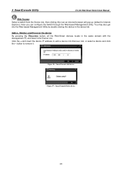
... Management Utility by double clicking the device in the Device List. Figure 26 - Here you can configure the Switch through the Web-based Management Utility. 4 SmartConsole Utility D-Link Web Smart Switch User Manual Web Access Select a switch from the Device List, then clicking this icon an internet browser will pop up (default is Internet Explorer). Add(+), Delete(-) and Discover the...
... Management Utility by double clicking the device in the Device List. Figure 26 - Here you can configure the Switch through the Web-based Management Utility. 4 SmartConsole Utility D-Link Web Smart Switch User Manual Web Access Select a switch from the Device List, then clicking this icon an internet browser will pop up (default is Internet Explorer). Add(+), Delete(-) and Discover the...


