
Product Manual
Page 2
Table of Contents D-Link Web Smart Switch User Manual Table of Contents Table of Contents ...i About This Guide...1 Terms/Usage...1 Copyright and Trademarks ...1 Product Introduction ...2 DGS-1210-16 ...3 Front Panel ...3 Rear Panel...3 DGS-1210-24 ...3 Front Panel ...3 Rear Panel...4 DGS-1210-48 ...4 Front Panel ...4 Rear Panel...5 Hardware Installation ...6 Step 1: Unpacking...6 Step 2:... the device 17 Device List...17 Configuration ...19 Smart Wizard Configuration...19 Password Settings...19 SNMP Settings ...20 System Settings...21 Web-based Management...22 Tool Bar > Save Menu ...23 i
Table of Contents D-Link Web Smart Switch User Manual Table of Contents Table of Contents ...i About This Guide...1 Terms/Usage...1 Copyright and Trademarks ...1 Product Introduction ...2 DGS-1210-16 ...3 Front Panel ...3 Rear Panel...3 DGS-1210-24 ...3 Front Panel ...3 Rear Panel...4 DGS-1210-48 ...4 Front Panel ...4 Rear Panel...5 Hardware Installation ...6 Step 1: Unpacking...6 Step 2:... the device 17 Device List...17 Configuration ...19 Smart Wizard Configuration...19 Password Settings...19 SNMP Settings ...20 System Settings...21 Web-based Management...22 Tool Bar > Save Menu ...23 i
Product Manual
Page 7
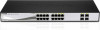
.... 1 Product Introduction D-Link Web Smart Switch User Manual DGS-1210-16 16-Port 10/100/1000Mbps with normal RJ-45 ports 13 to 16. Blinking indicates that the Switch is connected to a power source. DGS-1210-24 24-Port 10/100/1000Mbps with 4 Combo SFP Slot Web Smart Switch Front Panel Figure 3 - Port Link/Act/Speed LED (1-20, 21F, 22F...
.... 1 Product Introduction D-Link Web Smart Switch User Manual DGS-1210-16 16-Port 10/100/1000Mbps with normal RJ-45 ports 13 to 16. Blinking indicates that the Switch is connected to a power source. DGS-1210-24 24-Port 10/100/1000Mbps with 4 Combo SFP Slot Web Smart Switch Front Panel Figure 3 - Port Link/Act/Speed LED (1-20, 21F, 22F...
Product Manual
Page 19
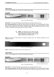
... has five icons: Device Settings Device Password Manager Multi Firmware Upgrade DHCP Refresh Web Access and the , , device buttons for the Device List. 4 SmartConsole Utility D-Link Web Smart Switch User Manual Device Configuration The Device Configuration in the Confirm Password box and then click OK Figure...
... has five icons: Device Settings Device Password Manager Multi Firmware Upgrade DHCP Refresh Web Access and the , , device buttons for the Device List. 4 SmartConsole Utility D-Link Web Smart Switch User Manual Device Configuration The Device Configuration in the Confirm Password box and then click OK Figure...

Product Manual
Page 24
5 Configuration D-Link Web Smart Switch User Manual SNMP Settings The SNMP Setting allows you to make it effective. Click Enabled, enter Community names, and then click Apply ... authorized management stations to retrieve and modify MIB object values. For the complete SNMP function, please check "Setup Menu > System > SNMP Settings" in Smart Wizard 20
5 Configuration D-Link Web Smart Switch User Manual SNMP Settings The SNMP Setting allows you to make it effective. Click Enabled, enter Community names, and then click Apply ... authorized management stations to retrieve and modify MIB object values. For the complete SNMP function, please check "Setup Menu > System > SNMP Settings" in Smart Wizard 20
Product Manual
Page 38
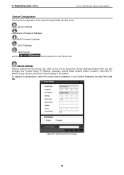
5 Configuration D-Link Web Smart Switch User Manual Figure 57 - Enabling Asymmetric VLAN 2. Configure the shared VLAN (VLAN 1) and access VLANs (VLAN 2, 3, 4) In this example are connected to the server Port 20 is connected to the firewall The group of ports to be separated from the other VLANs ... ports as PVID 2, 3 and 4 respectively. VLAN 4: Member ports are untagged port 5, 15-18, 20. Create VLANs 3. Assign PVID 34 VLAN 2: Member ports are untagged port 7, 15-18, 20. VLAN 3: Member ports are needed. Figure 58 - The purpose of the VLAN configuration page. Figure 59...
5 Configuration D-Link Web Smart Switch User Manual Figure 57 - Enabling Asymmetric VLAN 2. Configure the shared VLAN (VLAN 1) and access VLANs (VLAN 2, 3, 4) In this example are connected to the server Port 20 is connected to the firewall The group of ports to be separated from the other VLANs ... ports as PVID 2, 3 and 4 respectively. VLAN 4: Member ports are untagged port 5, 15-18, 20. Create VLANs 3. Assign PVID 34 VLAN 2: Member ports are untagged port 7, 15-18, 20. VLAN 3: Member ports are needed. Figure 58 - The purpose of the VLAN configuration page. Figure 59...
Product Manual
Page 44
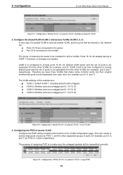
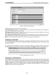
...connected devices are hubs or unmanaged switches. 5 Configuration D-Link Web Smart Switch User Manual Figure 68 - Configuration > Power Saving The Power Saving mode feature reduces power consumption automatically when the RJ-45 port is used (less than 20 meters). The Loopback Detection function can be implemented on a... range of the port. You may enable or disable this function using the pull-down links are turned off the mirroring of ports at the same time...
...connected devices are hubs or unmanaged switches. 5 Configuration D-Link Web Smart Switch User Manual Figure 68 - Configuration > Power Saving The Power Saving mode feature reduces power consumption automatically when the RJ-45 port is used (less than 20 meters). The Loopback Detection function can be implemented on a... range of the port. You may enable or disable this function using the pull-down links are turned off the mirroring of ports at the same time...

Product Manual
Page 47
...Delay (4-30 sec): This sets the maximum amount of time that old information does not endlessly circulate through redundant paths in faster detection of failed links, and thus faster topology adjustment. The default is 32768. The basic function and much of the new information. Set by the root device, thus...STP Version: You can be lost. The default setting is sensitive to the status of STP that the Switch is 2 seconds. The default value is 20. (Max Age has to have a value bigger than Hello Time) Hello Time (1-10 sec): The user may set the time interval between the ...
...Delay (4-30 sec): This sets the maximum amount of time that old information does not endlessly circulate through redundant paths in faster detection of failed links, and thus faster topology adjustment. The default is 32768. The basic function and much of the new information. Set by the root device, thus...STP Version: You can be lost. The default setting is sensitive to the status of STP that the Switch is 2 seconds. The default value is 20. (Max Age has to have a value bigger than Hello Time) Hello Time (1-10 sec): The user may set the time interval between the ...
