Reference Guide
Page 2
... Management Options...9 Using Web-based Management ...9 Supported Web Browsers ...9 Connecting to the Switch...9 Login Web-based Management ...10 Smart Wizard ...10 Web-based Management...10 SmartConsole Utility...10 4 SmartConsole Utility ...12 SmartConsole Settings ...12 Utility Settings...12 Log...12 Trap ...13 File ...13 Help ...14 Device Configuration...14 Add(+), Delete(-) and Discover the device 16 Device List...16 5 Configuration ...18 Smart Wizard Configuration...18 IP Information ...18 Password...18 i Table of Contents D-Link Web Smart Switch User Manual Table of Contents Table...
... Management Options...9 Using Web-based Management ...9 Supported Web Browsers ...9 Connecting to the Switch...9 Login Web-based Management ...10 Smart Wizard ...10 Web-based Management...10 SmartConsole Utility...10 4 SmartConsole Utility ...12 SmartConsole Settings ...12 Utility Settings...12 Log...12 Trap ...13 File ...13 Help ...14 Device Configuration...14 Add(+), Delete(-) and Discover the device 16 Device List...16 5 Configuration ...18 Smart Wizard Configuration...18 IP Information ...18 Password...18 i Table of Contents D-Link Web Smart Switch User Manual Table of Contents Table...

Reference Guide
Page 3
Table of Contents D-Link Web Smart Switch User Manual SNMP ...19 Web-based Management...21 Tool Bar > Save Menu ...22 Save Configuration ...22 Save Log ...22 Tool Bar > Tool Menu ...22 Reset ...22 Reset System ...22 Reboot Device ...22 Configuration Backup and Restore ...23 Firmware Backup and Upgrade...23 Tool Bar > Smart Wizard...24 Tool Bar > Online Help...24 Function Tree ...26 Device Information...26 System > System Settings ...27 System > Password...27 System > Port Settings...27 System > DHCP Auto Configuration ...28 System > SysLog Host...
Table of Contents D-Link Web Smart Switch User Manual SNMP ...19 Web-based Management...21 Tool Bar > Save Menu ...22 Save Configuration ...22 Save Log ...22 Tool Bar > Tool Menu ...22 Reset ...22 Reset System ...22 Reboot Device ...22 Configuration Backup and Restore ...23 Firmware Backup and Upgrade...23 Tool Bar > Smart Wizard...24 Tool Bar > Online Help...24 Function Tree ...26 Device Information...26 System > System Settings ...27 System > Password...27 System > Port Settings...27 System > DHCP Auto Configuration ...28 System > SysLog Host...
Reference Guide
Page 6
..., network connections, and technical specifications. About This Guide D-Link Web Smart Switch User Manual About This Guide This guide provides instructions to install the D-Link Gigabit Web Smart Switch DGS-1210-20/28/28P/52, how to use of D-Link Corporation; Note: The model you have purchased may be used in this document is subjected to change without the written permission of Microsoft Corporation. Refer to the central management system. 4. Hardware Installation: Step-by -step. Some technologies refer to terms "switch", "bridge" and "switching hubs...
..., network connections, and technical specifications. About This Guide D-Link Web Smart Switch User Manual About This Guide This guide provides instructions to install the D-Link Gigabit Web Smart Switch DGS-1210-20/28/28P/52, how to use of D-Link Corporation; Note: The model you have purchased may be used in this document is subjected to change without the written permission of Microsoft Corporation. Refer to the central management system. 4. Hardware Installation: Step-by -step. Some technologies refer to terms "switch", "bridge" and "switching hubs...
Reference Guide
Page 7
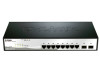
... versatile management. Some basic tasks can be performed such as DGS1210-28P, D-Link Green Technology offers Time-based PoE feature to work seamlessly with easy-to the port level. The DGS-1210 series is another simple but useful authentication method to change or firmware upgrade. The switches support 802.1Q VLAN standard tagging to factory defaults, setting the administrator password, rebooting the Switch, or upgrading the Switch firmware by prioritizing that allows administrators to remotely control their network, using the Command Line Interface (CLI...
... versatile management. Some basic tasks can be performed such as DGS1210-28P, D-Link Green Technology offers Time-based PoE feature to work seamlessly with easy-to the port level. The DGS-1210 series is another simple but useful authentication method to change or firmware upgrade. The switches support 802.1Q VLAN standard tagging to factory defaults, setting the administrator password, rebooting the Switch, or upgrading the Switch firmware by prioritizing that allows administrators to remotely control their network, using the Command Line Interface (CLI...
Reference Guide
Page 9
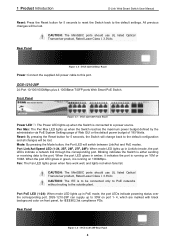
... D-Link Web Smart Switch User Manual Reset: Press the Reset button for IEEE802.3at compliance PDs. CAUTION: The MiniGBIC ports should use UL listed Optical Transceiver product, Rated Laser Class I . 3.3Vdc. DGS-1210-28P Front Panel Power LED : The Power LED lights up when the Switch is either sending or receiving data to a power source. Blinking indicates the Switch is connected to the port. Front Panel Figure 1.5 - When the port LED glows in amber, it is to the outside plant. Fan...
... D-Link Web Smart Switch User Manual Reset: Press the Reset button for IEEE802.3at compliance PDs. CAUTION: The MiniGBIC ports should use UL listed Optical Transceiver product, Rated Laser Class I . 3.3Vdc. DGS-1210-28P Front Panel Power LED : The Power LED lights up when the Switch is either sending or receiving data to a power source. Blinking indicates the Switch is connected to the port. Front Panel Figure 1.5 - When the port LED glows in amber, it is to the outside plant. Fan...

Reference Guide
Page 14
... an IP address in the same range as the switch. A standard Ethernet cable Connect the Ethernet cable to initialize multiple Smart Switches. Connected Ethernet cable 9 Supported Web Browsers The embedded Web-based Management currently supports the following installation instructions for communication with a RJ-45 Ethernet connection 2. Each switch must be managed through any port on the PC. 3 Getting Started D-Link Web Smart Switch User Manual 3 Getting Started This chapter introduces the management interface of the switch and to access the Web-Based Management concurrently. A PC...
... an IP address in the same range as the switch. A standard Ethernet cable Connect the Ethernet cable to initialize multiple Smart Switches. Connected Ethernet cable 9 Supported Web Browsers The embedded Web-based Management currently supports the following installation instructions for communication with a RJ-45 Ethernet connection 2. Each switch must be managed through any port on the PC. 3 Getting Started D-Link Web Smart Switch User Manual 3 Getting Started This chapter introduces the management interface of the switch and to access the Web-Based Management concurrently. A PC...

Reference Guide
Page 15
... the address bar. SmartConsole Utility The SmartConsole Utility included in the Smart Wizard, you through essential settings of the D-Link Web Smart Switch. Then press . Please refer to the Smart Wizard Configuration section for detailed instructions. Web-based Management By clicking the Exit button in the installation CD is a program for the installation of the Webbased Management interface then click OK. This will guide you will enter the Web-based Management interface...
... the address bar. SmartConsole Utility The SmartConsole Utility included in the Smart Wizard, you through essential settings of the D-Link Web Smart Switch. Then press . Please refer to the Smart Wizard Configuration section for detailed instructions. Web-based Management By clicking the Exit button in the installation CD is a program for the installation of the Webbased Management interface then click OK. This will guide you will enter the Web-based Management interface...
Reference Guide
Page 28
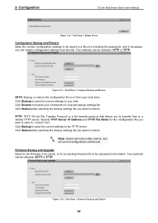
...configurations will be lost Firmware Backup and Upgrade Allow for the firmware to be saved to a file (not including the password), and if necessary, you to transfer files to / restore from this file. Click Backup to save to a remote TFTP server. Note: Switch will reboot after selecting the backup settings file you want to be saved, or for a saved backup settings file. Tool Menu > Reboot Device Configuration Backup and Restore Allow the current configuration settings to restore. 5 Configuration D-Link Web Smart Switch User Manual Figure 5.12 - TFTP: TFTP (Trivial File...
...configurations will be lost Firmware Backup and Upgrade Allow for the firmware to be saved to a file (not including the password), and if necessary, you to transfer files to / restore from this file. Click Backup to save to a remote TFTP server. Note: Switch will reboot after selecting the backup settings file you want to be saved, or for a saved backup settings file. Tool Menu > Reboot Device Configuration Backup and Restore Allow the current configuration settings to restore. 5 Configuration D-Link Web Smart Switch User Manual Figure 5.12 - TFTP: TFTP (Trivial File...

Reference Guide
Page 31
It also offers an overall status of the screen. DHCP Client: Click Settings to link to L2 Functions > Multicast > IGMP Snooping. IGMP Snooping: Click Settings to link to System > DHCP Auto Configuration. Power Saving: Click Settings to link to Security > Safeguard Engine. 5 Configuration D-Link Web Smart Switch User Manual Function Tree All configuration options on the switch are accessed through the Setup menu on the setup item that you want to configure. Figure 5.17 -Function Tree Device Information The Device Information provides an overview...
It also offers an overall status of the screen. DHCP Client: Click Settings to link to L2 Functions > Multicast > IGMP Snooping. IGMP Snooping: Click Settings to link to System > DHCP Auto Configuration. Power Saving: Click Settings to link to Security > Safeguard Engine. 5 Configuration D-Link Web Smart Switch User Manual Function Tree All configuration options on the switch are accessed through the Setup menu on the setup item that you want to configure. Figure 5.17 -Function Tree Device Information The Device Information provides an overview...

Reference Guide
Page 32
..., and the default setting is a critical tool for the changes to secure the Web-Smart Switch. Selective range is required a re-login before using static mode, the IP Address, Subnet Mask and Gateway can more easily be manually configured. System > Password Access Control System > Port Settings In the Port Setting page, the status of all selected ports by clicking Apply. If the current session times out (expires), the user is from other Web-Smart devices on the...
..., and the default setting is a critical tool for the changes to secure the Web-Smart Switch. Selective range is required a re-login before using static mode, the IP Address, Subnet Mask and Gateway can more easily be manually configured. System > Password Access Control System > Port Settings In the Port Setting page, the status of all selected ports by clicking Apply. If the current session times out (expires), the user is from other Web-Smart devices on the...

Reference Guide
Page 33
... the DHCP reply packet. Auto MDI/MDIX is designed on a PC. When connecting the Switch to end stations, user have to detect if the connection is Disabled. The TFTP server must deliver the TFTP server IP address and configuration file name information in its base directory when the request is "Auto" MDI/MDIX. Switches and hubs usually use straight through Ethernet cables to adjust port speed settings appropriately after changing the connected cable media types. 5 Configuration D-Link Web Smart Switch User Manual Figure 5.21 - The default setting...
... the DHCP reply packet. Auto MDI/MDIX is designed on a PC. When connecting the Switch to end stations, user have to detect if the connection is Disabled. The TFTP server must deliver the TFTP server IP address and configuration file name information in its base directory when the request is "Auto" MDI/MDIX. Switches and hubs usually use straight through Ethernet cables to adjust port speed settings appropriately after changing the connected cable media types. 5 Configuration D-Link Web Smart Switch User Manual Figure 5.21 - The default setting...

Reference Guide
Page 40
... the Auto Surveillance VLAN summary table. System will automatically detect D-Link Surveillance Devices by the Auto Surveillance VLAN. Default is disabled, Select Enabled then click Apply to be the static member port of Auto Surveillance VLAN global settings. The possible values are Video Management Server (VMS), VMS Client/Remote viewer, Video Encoder, Network Storage and Other IP Surveillance Devices. Figure 5.35 - Tagged Uplink/Downlink Port: Specifies the ports to turn on the jumbo frame support. 5 Configuration D-Link Web Smart Switch User Manual VLAN...
... the Auto Surveillance VLAN summary table. System will automatically detect D-Link Surveillance Devices by the Auto Surveillance VLAN. Default is disabled, Select Enabled then click Apply to be the static member port of Auto Surveillance VLAN global settings. The possible values are Video Management Server (VMS), VMS Client/Remote viewer, Video Encoder, Network Storage and Other IP Surveillance Devices. Figure 5.35 - Tagged Uplink/Downlink Port: Specifies the ports to turn on the jumbo frame support. 5 Configuration D-Link Web Smart Switch User Manual VLAN...

Reference Guide
Page 41
... of ports may be set at the same time. From Port: The beginning of a consecutive group of ports at 0 seconds, or 60 to include all " to 1000000 seconds. 5 Configuration D-Link Web Smart Switch User Manual RX (receive) mode: Duplicates the data that is received from the source port and forwards it to the administrator. Click "all ports from mirroring. Click Apply to remove all " to implement changes made. L2 Functions > MAC Address Table > Static Mac Address...
... of ports may be set at the same time. From Port: The beginning of a consecutive group of ports at 0 seconds, or 60 to include all " to 1000000 seconds. 5 Configuration D-Link Web Smart Switch User Manual RX (receive) mode: Duplicates the data that is received from the source port and forwards it to the administrator. Click "all ports from mirroring. Click Apply to remove all " to implement changes made. L2 Functions > MAC Address Table > Static Mac Address...

Reference Guide
Page 45
... frame's Layer 2 MAC header. LACP ports that are : Short (3 Sec) - L2 Functions > Link Aggregation > LACP Port Settings The LACP Port Settings is the default value. 5 Configuration D-Link Web Smart Switch User Manual Figure 5.41 - In order to allow the linked port group to negotiate the aggregated link so the group may set which ports will forward multicast traffic only to connections that is, to change an aggregated port group, that have "active" LACP ports. The user may be active and passive in processing and sending LACP control frames. This allows LACP...
... frame's Layer 2 MAC header. LACP ports that are : Short (3 Sec) - L2 Functions > Link Aggregation > LACP Port Settings The LACP Port Settings is the default value. 5 Configuration D-Link Web Smart Switch User Manual Figure 5.41 - In order to allow the linked port group to negotiate the aggregated link so the group may set which ports will forward multicast traffic only to connections that is, to change an aggregated port group, that have "active" LACP ports. The user may be active and passive in processing and sending LACP control frames. This allows LACP...

Reference Guide
Page 46
.... For each host port learned, a 'Port Purge Timer' runs for a given VLAN, select enable and click on a subnet. Max Response Time (10-25 sec): The Max Response Time specifies the maximum allowed time before sending a responding report message. Figure 5.43 - Default is disabled. 5 Configuration D-Link Web Smart Switch User Manual The settings of IGMP snooping is set to zero, and it SHOULD NOT be. If enabled, the IGMP Global Settings will be purged from...
.... For each host port learned, a 'Port Purge Timer' runs for a given VLAN, select enable and click on a subnet. Max Response Time (10-25 sec): The Max Response Time specifies the maximum allowed time before sending a responding report message. Figure 5.43 - Default is disabled. 5 Configuration D-Link Web Smart Switch User Manual The settings of IGMP snooping is set to zero, and it SHOULD NOT be. If enabled, the IGMP Global Settings will be purged from...

Reference Guide
Page 71
Figure 5.87 - Default setting is Normal. Default is N/A. To protect the DGS-1210-28P and the connected devices, the power limit function will display the PoE status including, Port Enable, Power Limit, Power (W), Voltage (V), Current (mA), Classification, Port Status. PoE > PoE Port Setting From Port/To Port: Specifies the PoE function of the switch. 5 Configuration D-Link Web Smart Switch User Manual Power Used: Displays the current used power of a port or ports. It supplies power to PD device up to 15.4W for all non-802.3af capable D-Link AP...
Figure 5.87 - Default setting is Normal. Default is N/A. To protect the DGS-1210-28P and the connected devices, the power limit function will display the PoE status including, Port Enable, Power Limit, Power (W), Voltage (V), Current (mA), Classification, Port Status. PoE > PoE Port Setting From Port/To Port: Specifies the PoE function of the switch. 5 Configuration D-Link Web Smart Switch User Manual Power Used: Displays the current used power of a port or ports. It supplies power to PD device up to 15.4W for all non-802.3af capable D-Link AP...
Reference Guide
Page 72
...: The total PoE power budget is an OSI Layer 7 (Application Layer) protocol designed specifically for managing and monitoring network devices. 5 Configuration D-Link Web Smart Switch User Manual function of the originating PC. Note: For the PoE Port Settings table, if the classification was shown as "Legacy PD", it allows SmartConsole Utility to the switch. Destination IP: Specifies the destination IP. Firmware Upgrade State: Information of a RSTP port state changes. The remaining 7watts is enabled, enter...
...: The total PoE power budget is an OSI Layer 7 (Application Layer) protocol designed specifically for managing and monitoring network devices. 5 Configuration D-Link Web Smart Switch User Manual function of the originating PC. Note: For the PoE Port Settings table, if the classification was shown as "Legacy PD", it allows SmartConsole Utility to the switch. Destination IP: Specifies the destination IP. Firmware Upgrade State: Information of a RSTP port state changes. The remaining 7watts is enabled, enter...

Reference Guide
Page 73
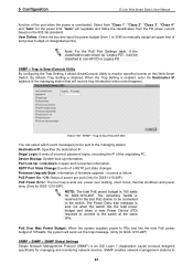
... Switch. 68 5 Configuration D-Link Web Smart Switch User Manual read and modify the settings of the originating PC. SNMP Authentication Traps: Specifies the device to the switch at the same time. Illegal Login: Events of incorrect password logins, recording the IP of gateways, routers, switches, and other network devices. PoE Over Max Power Budget: When the system supplies power to as an agent), which provides a standard presentation of a RSTP port state changes. Managed devices that support SNMP include software (referred...
... Switch. 68 5 Configuration D-Link Web Smart Switch User Manual read and modify the settings of the originating PC. SNMP Authentication Traps: Specifies the device to the switch at the same time. Illegal Login: Events of incorrect password logins, recording the IP of gateways, routers, switches, and other network devices. PoE Over Max Power Budget: When the system supplies power to as an agent), which provides a standard presentation of a RSTP port state changes. Managed devices that support SNMP include software (referred...
Reference Guide
Page 81
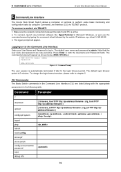
... Line Interface D-Link Web Smart Switch User Manual 6 Command Line Interface The D-Link Web Smart Switch allows a computer or terminal to perform some basic monitoring and configuration tasks by the switch IP address, eg. To connect, launch any terminal software like HyperTerminal in Microsoft Windows, or just use the command prompt by typing the command telnet followed by using the Command Line Interface (CLI) via TELNET: 1. The default user name and password is automatically terminated if idle for the login timeout period. download upload config ipif system logout ping reboot reset...
... Line Interface D-Link Web Smart Switch User Manual 6 Command Line Interface The D-Link Web Smart Switch allows a computer or terminal to perform some basic monitoring and configuration tasks by the switch IP address, eg. To connect, launch any terminal software like HyperTerminal in Microsoft Windows, or just use the command prompt by typing the command telnet followed by using the Command Line Interface (CLI) via TELNET: 1. The default user name and password is automatically terminated if idle for the login timeout period. download upload config ipif system logout ping reboot reset...
Reference Guide
Page 92
... control Web-based configuration backup / restoration Web-based firmware backup/restore Firmware upgrade using SmartConsole Utility & Web-based management Reset, Reboot ACL Max 50 ingress ACL profiles Ingress ACL rules: - DGS-1210-52: 450 rules 87 By Port Shut-Off: Each port on the system can be turned on the system enters sleep state by port or system through schedule. - Technical Specifications D-Link Web Smart Switch User Manual LLDP L2 Multicast Filtering D-Link Green Technology Power Saving: Enabled by schedule. - By Link Status: Drastically save power: - For example...
... control Web-based configuration backup / restoration Web-based firmware backup/restore Firmware upgrade using SmartConsole Utility & Web-based management Reset, Reboot ACL Max 50 ingress ACL profiles Ingress ACL rules: - DGS-1210-52: 450 rules 87 By Port Shut-Off: Each port on the system can be turned on the system enters sleep state by port or system through schedule. - Technical Specifications D-Link Web Smart Switch User Manual LLDP L2 Multicast Filtering D-Link Green Technology Power Saving: Enabled by schedule. - By Link Status: Drastically save power: - For example...


