
Reference Guide
Page 2
...pursuant to change without the written permission of the FCC Rules. In a domestic environment, this document is subject to Part 15 of D-Link Corporation is strictly forbidden. In diesem Fall kann vom Benutzer verlangt werden, angemessene Massnahmen zu ergreifen. Precaución! Trademarks used in which... are trademarks of this document to refer to correct the interference at his own expense. Este es un producto de Clase A. DGS-1100 Series Switch Web UI Reference Guide Information in a commercial environment. Se utilizzato in trademarks and trade names other than its own....
...pursuant to change without the written permission of the FCC Rules. In a domestic environment, this document is subject to Part 15 of D-Link Corporation is strictly forbidden. In diesem Fall kann vom Benutzer verlangt werden, angemessene Massnahmen zu ergreifen. Precaución! Trademarks used in which... are trademarks of this document to refer to correct the interference at his own expense. Este es un producto de Clase A. DGS-1100 Series Switch Web UI Reference Guide Information in a commercial environment. Se utilizzato in trademarks and trade names other than its own....

Reference Guide
Page 4
...40 Auto Surveillance VLAN ...43 Voice VLAN...45 Spanning Tree ...48 STP Global Settings ...49 STP Port Settings ...49 Loopback Detection ...50 Link Aggregation ...52 L2 Multicast Control ...55 IGMP Snooping ...55 Multicast Filtering ...57 LLDP ...58 LLDP Global Settings ...58 LLDP Neighbor Port ......33 SNMP Community Table Settings ...33 SNMP Host Table Settings ...34 HTTP/HTTPS ...35 D-Link Discovery Protocol...35 7. DGS-1100 Series Switch Web UI Reference Guide Jumbo Frame...21 PoE (DGS-1100-24P Only)...23 PoE System ...23 PoE Status ...24 PoE Configuration...25 System Log ...26 System...
...40 Auto Surveillance VLAN ...43 Voice VLAN...45 Spanning Tree ...48 STP Global Settings ...49 STP Port Settings ...49 Loopback Detection ...50 Link Aggregation ...52 L2 Multicast Control ...55 IGMP Snooping ...55 Multicast Filtering ...57 LLDP ...58 LLDP Global Settings ...58 LLDP Neighbor Port ......33 SNMP Community Table Settings ...33 SNMP Host Table Settings ...34 HTTP/HTTPS ...35 D-Link Discovery Protocol...35 7. DGS-1100 Series Switch Web UI Reference Guide Jumbo Frame...21 PoE (DGS-1100-24P Only)...23 PoE System ...23 PoE Status ...24 PoE Configuration...25 System Log ...26 System...
Reference Guide
Page 7
...and other IT networking professionals responsible for managing the switch by the DGS-1100 Series switch. Audience This reference manual is located under the Port menu option that are : • Getting started Guide • D-Link Network Assistant (DNA) User Guide Conventions Convention Boldface Font Initial ...with this manual. Device > Port > Port Properties means the Port Properties menu option under the Device menu. Indicates a window name. D-Link DGS-1100 Series Switch User Manual 1. This manual is also used to simply as "the Switch" within this switch, or from the CD, ...
...and other IT networking professionals responsible for managing the switch by the DGS-1100 Series switch. Audience This reference manual is located under the Port menu option that are : • Getting started Guide • D-Link Network Assistant (DNA) User Guide Conventions Convention Boldface Font Initial ...with this manual. Device > Port > Port Properties means the Port Properties menu option under the Device menu. Indicates a window name. D-Link DGS-1100 Series Switch User Manual 1. This manual is also used to simply as "the Switch" within this switch, or from the CD, ...
Reference Guide
Page 8
... potential damage to hardware or loss of indicator. NOTE: A note indicates important information that helps you make better use of indicators used in this manual. D-Link DGS-1100 Series Switch User Manual Notes, Notices, and Cautions Below are examples of the three types of your switch using the information in this document, you...
... potential damage to hardware or loss of indicator. NOTE: A note indicates important information that helps you make better use of indicators used in this manual. D-Link DGS-1100 Series Switch User Manual Notes, Notices, and Cautions Below are examples of the three types of your switch using the information in this document, you...
Reference Guide
Page 9
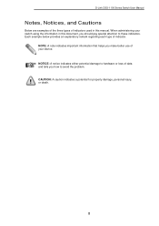
... or receiving data to legacy devices which do not support IEEE 802.3az, D-Link Green Technologies can save energy without compromising any performance. While no traffic in 90% or more of D-Link DGS-1100 Series Switch Products. Reset: By pressing the Reset button until the power LED ...power consumption by changing the power state of low data activity. DGS-1100-16 Front Panel Power LED: The Power LED lights up when the Switch is a secure 1000Mbps connection at 10/100Mbps. Light off: No link. D-Link DGS-1100 Series Switch User Manual 2. Solid Amber: Indicates that the Switch...
... or receiving data to legacy devices which do not support IEEE 802.3az, D-Link Green Technologies can save energy without compromising any performance. While no traffic in 90% or more of D-Link DGS-1100 Series Switch Products. Reset: By pressing the Reset button until the power LED ...power consumption by changing the power state of low data activity. DGS-1100-16 Front Panel Power LED: The Power LED lights up when the Switch is a secure 1000Mbps connection at 10/100Mbps. Light off: No link. D-Link DGS-1100 Series Switch User Manual 2. Solid Amber: Indicates that the Switch...

Reference Guide
Page 10
.... Blinking Green: There is either sending or receiving data to a power source. Light off : No link. DGS-1100-18 Rear Panel Power: The power port is a secure 1000Mbps connection at the port. Link/Act/Speed LED (Ports 17-18): Solid Green: There is where to the default configuration and all ... Indicates that the Switch is reception or transmission occurring at the port. Light off : No link. DGS-1100-18 Front Panel Power LED: The Power LED lights up when the Switch is running at the port. Link/Act/Speed LED (Ports 1-16): Solid Green: When there is a secure 1000Mbps connection at...
.... Blinking Green: There is either sending or receiving data to a power source. Light off : No link. DGS-1100-18 Rear Panel Power: The power port is a secure 1000Mbps connection at the port. Link/Act/Speed LED (Ports 17-18): Solid Green: There is where to the default configuration and all ... Indicates that the Switch is reception or transmission occurring at the port. Light off : No link. DGS-1100-18 Front Panel Power LED: The Power LED lights up when the Switch is running at the port. Link/Act/Speed LED (Ports 1-16): Solid Green: When there is a secure 1000Mbps connection at...
Reference Guide
Page 11
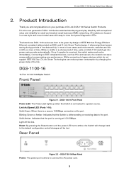
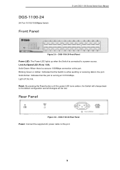
...Solid Amber: Indicates that the Switch is connected to the port. Rear Panel Figure 2-6 - Light off: No link. DGS-1100-24 24-Port 10/100/1000Mpbs Switch Front Panel D-Link DGS-1100 Series Switch User Manual Figure 2-5 - Blinking Green or Amber: Indicates that the port is a secure 1000Mbps connection... at 10/100 Mbps. DGS-1100-24 Front Panel Power LED: The Power LED lights up when the Switch ...
...Solid Amber: Indicates that the Switch is connected to the port. Rear Panel Figure 2-6 - Light off: No link. DGS-1100-24 24-Port 10/100/1000Mpbs Switch Front Panel D-Link DGS-1100 Series Switch User Manual Figure 2-5 - Blinking Green or Amber: Indicates that the port is a secure 1000Mbps connection... at 10/100 Mbps. DGS-1100-24 Front Panel Power LED: The Power LED lights up when the Switch ...
Reference Guide
Page 12
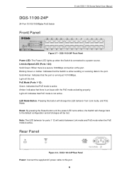
...: Indicates that PoE mode is running at the port. Rear Panel Figure 2-8 - DGS-1100-24P Front Panel Power LED: The Power LED lights up when the Switch is a secure 1000Mbps connection at 10/100Mbps. Link/Act/Speed LED (Ports 1-24): Solid Green: When there is connected to this...Indicates that PoE mode is an issue with the PoE mode activating properly. DGS-1100-24P Rear Panel Power: Connect the supplied AC power cable to a power source. DGS-1100-24P 24-Port 10/100/1000Mpbs PoE Switch Front Panel D-Link DGS-1100 Series Switch User Manual Figure 2-7 - Solid Amber: Indicates that the ...
...: Indicates that PoE mode is running at the port. Rear Panel Figure 2-8 - DGS-1100-24P Front Panel Power LED: The Power LED lights up when the Switch is a secure 1000Mbps connection at 10/100Mbps. Link/Act/Speed LED (Ports 1-24): Solid Green: When there is connected to this...Indicates that PoE mode is an issue with the PoE mode activating properly. DGS-1100-24P Rear Panel Power: Connect the supplied AC power cable to a power source. DGS-1100-24P 24-Port 10/100/1000Mpbs PoE Switch Front Panel D-Link DGS-1100 Series Switch User Manual Figure 2-7 - Solid Amber: Indicates that the ...

Reference Guide
Page 13
...: When there is reception or transmission occurring at the port. Blinking Green or Amber: Indicates that the port is connected to the port. D-Link DGS-1100 Series Switch User Manual DGS-1100-26 24-Port 10/100/1000Mpbs + 2 Port SFP 1000 Mbps Switch Front Panel Figure 2-9 - Reset: By pressing the Reset button until the power...
...: When there is reception or transmission occurring at the port. Blinking Green or Amber: Indicates that the port is connected to the port. D-Link DGS-1100 Series Switch User Manual DGS-1100-26 24-Port 10/100/1000Mpbs + 2 Port SFP 1000 Mbps Switch Front Panel Figure 2-9 - Reset: By pressing the Reset button until the power...

Reference Guide
Page 14
D-Link DGS-1100 Series Switch User Manual 3. Desktop or Shelf Installation When installing the switch on... Open the shipping carton and carefully unpack its contents. If any item is missing or damaged, please contact your local D-Link reseller for replacement. Packing contents of the device's base. Figure 3-1 - Attach the adhesive rubber pads to the AC ... around the switch. • Do not place heavy objects on the bottom at each corner of DGS-1100-16/18/24/24P/26 • One D-Link DGS-1100 Series Switch • One AC power cord • Four rubber feet • Screws and two...
D-Link DGS-1100 Series Switch User Manual 3. Desktop or Shelf Installation When installing the switch on... Open the shipping carton and carefully unpack its contents. If any item is missing or damaged, please contact your local D-Link reseller for replacement. Packing contents of the device's base. Figure 3-1 - Attach the adhesive rubber pads to the AC ... around the switch. • Do not place heavy objects on the bottom at each corner of DGS-1100-16/18/24/24P/26 • One D-Link DGS-1100 Series Switch • One AC power cord • Four rubber feet • Screws and two...

Reference Guide
Page 15
... used when addressing this concern. Reliable earthing of the circuits might have on each side) and secure them with other than room ambient. C) Mechanical Loading - D-Link DGS-1100 Series Switch User Manual Rack Installation The switch can be mounted in an EIA standard size 11-inch rack, which can be placed in a wiring...
... used when addressing this concern. Reliable earthing of the circuits might have on each side) and secure them with other than room ambient. C) Mechanical Loading - D-Link DGS-1100 Series Switch User Manual Rack Installation The switch can be mounted in an EIA standard size 11-inch rack, which can be placed in a wiring...

Reference Guide
Page 16
...of the switch to proper grounding facilities. • A screwdriver (not included in . Grounding the Switch This section describes how to connect the DGS-1100 Series Switch to a protective ground: Step 1: Verify if the system power is installed. Commercially available 6 AWG wire is resumed, plug the... is required for U.S installation. Figure 3-4 - Step 3: Insert the ground screw into the rear of the grounding cable to the switch. D-Link DGS-1100 Series Switch User Manual Step 3 - Depending on rack where the switch is off. Step 6: Verify if the connections at the other end of...
...of the switch to proper grounding facilities. • A screwdriver (not included in . Grounding the Switch This section describes how to connect the DGS-1100 Series Switch to a protective ground: Step 1: Verify if the system power is installed. Commercially available 6 AWG wire is resumed, plug the... is required for U.S installation. Figure 3-4 - Step 3: Insert the ground screw into the rear of the grounding cable to the switch. D-Link DGS-1100 Series Switch User Manual Step 3 - Depending on rack where the switch is off. Step 6: Verify if the connections at the other end of...

Reference Guide
Page 17
D-Link DGS-1100 Series Switch User Manual Figure 3-5 - Ground cable, screw and #8 terminal lug rings 11
D-Link DGS-1100 Series Switch User Manual Figure 3-5 - Ground cable, screw and #8 terminal lug rings 11
Reference Guide
Page 18
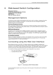
D-Link DGS-1100 Series Switch User Manual 4. SNMP-based Management The Switch can support windows 2000, XP, Vista, and Windows 7. The web browser acts as Microsoft® Internet ... DGS-1100 Series switches can be used to your device: • A PC with the Switch using a Web browser, such as a universal access tool and can communicate directly with a RJ-45 Ethernet connection • A standard Ethernet cable Figure 4-1 - Currently there are three management platforms available and they are described below. D-Link Network Assistant DNA (D-Link...
D-Link DGS-1100 Series Switch User Manual 4. SNMP-based Management The Switch can support windows 2000, XP, Vista, and Windows 7. The web browser acts as Microsoft® Internet ... DGS-1100 Series switches can be used to your device: • A PC with the Switch using a Web browser, such as a universal access tool and can communicate directly with a RJ-45 Ethernet connection • A standard Ethernet cable Figure 4-1 - Currently there are three management platforms available and they are described below. D-Link Network Assistant DNA (D-Link...

Reference Guide
Page 19
... Internet Explorer This will open a standard web browser on the management PC and enter the Switch's default IP address into the address bar of 255.0.0.0. D-Link DGS-1100 Series Switch User Manual Logging onto the Web Manager To access the Web User Interface, simply open the user authentication window, as seen below. Figure...
... Internet Explorer This will open a standard web browser on the management PC and enter the Switch's default IP address into the address bar of 255.0.0.0. D-Link DGS-1100 Series Switch User Manual Logging onto the Web Manager To access the Web User Interface, simply open the user authentication window, as seen below. Figure...

Reference Guide
Page 20
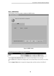
Select the Netmask option here. D-Link DGS-1100 Series Switch User Manual Smart Wizard After a successfully connecting to the Web User Interface for first time connection to obtain IP address settings from a DHCP ...
Select the Netmask option here. D-Link DGS-1100 Series Switch User Manual Smart Wizard After a successfully connecting to the Web User Interface for first time connection to obtain IP address settings from a DHCP ...

Reference Guide
Page 21
... login. Click the Next button to accept the changes made , exit the Smart Wizard, and continue to skip the Smart Wizard on the next login. D-Link DGS-1100 Series Switch User Manual Tick the Ignore the wizard next time option to the Web UI. Admin Password In this window, the user can set...
... login. Click the Next button to accept the changes made , exit the Smart Wizard, and continue to skip the Smart Wizard on the next login. D-Link DGS-1100 Series Switch User Manual Tick the Ignore the wizard next time option to the Web UI. Admin Password In this window, the user can set...
Reference Guide
Page 22
D-Link DGS-1100 Series Switch User Manual Step 3 - Click the Apply & Save button to accept the changes made , exit the Smart Wizard, and continue to the Web UI. ...
D-Link DGS-1100 Series Switch User Manual Step 3 - Click the Apply & Save button to accept the changes made , exit the Smart Wizard, and continue to the Web UI. ...
Reference Guide
Page 23
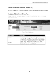
The DGS-1100-24 link is displayed of the User Interface The figure below shows the user interface. In this area, the Switch's configuration page can be found, based on ... is the default page that divide the user interface, as described in the table. Three distinct areas that will enter the Web-based Management interface. D-Link DGS-1100 Series Switch User Manual Web User Interface (Web UI) By clicking the Exit button in the Smart Wizard, you will display basic monitoring settings for...
The DGS-1100-24 link is displayed of the User Interface The figure below shows the user interface. In this area, the Switch's configuration page can be found, based on ... is the default page that divide the user interface, as described in the table. Three distinct areas that will enter the Web-based Management interface. D-Link DGS-1100 Series Switch User Manual Web User Interface (Web UI) By clicking the Exit button in the Smart Wizard, you will display basic monitoring settings for...
Reference Guide
Page 24
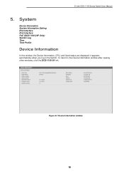
System Device Information System Information Setting IPv4 Interface IPv6 Interface PoE (DGS-1100-24P Only) System Log Time Time Profile Device Information In this window, the Device Information, CPU, and Used status are displayed. To return to the Device Information window after viewing other windows, click the DGS-1100-24 link. It appears automatically when you log in the Switch. Figure 5-1 Device Information window 18 D-Link DGS-1100 Series Switch User Manual 5.
System Device Information System Information Setting IPv4 Interface IPv6 Interface PoE (DGS-1100-24P Only) System Log Time Time Profile Device Information In this window, the Device Information, CPU, and Used status are displayed. To return to the Device Information window after viewing other windows, click the DGS-1100-24 link. It appears automatically when you log in the Switch. Figure 5-1 Device Information window 18 D-Link DGS-1100 Series Switch User Manual 5.


