
Manual
Page 2
D-Link EasySmart Switch User Manual Table of Contents Table of Contents ...i About This Guide ...1 Terms/Usage...1 Copyright and Trademarks ...1 1 Product Introduction ...2 DGS-1100-05 ...2 Front Panel ...2 Rear Panel...2 DGS-1100-08 ...2 Front Panel ...3 Rear Panel...3 DGS-1100-08P...3 Front Panel ...3 Rear Panel...4 DGS-1100-16 ...4 Front Panel ...4 Rear Panel...5 DGS-1100-24 ...5 Front Panel ...5 Rear Panel...5 2 Hardware Installation ...6 Step 1: Unpacking...6 Packing contents of...
D-Link EasySmart Switch User Manual Table of Contents Table of Contents ...i About This Guide ...1 Terms/Usage...1 Copyright and Trademarks ...1 1 Product Introduction ...2 DGS-1100-05 ...2 Front Panel ...2 Rear Panel...2 DGS-1100-08 ...2 Front Panel ...3 Rear Panel...3 DGS-1100-08P...3 Front Panel ...3 Rear Panel...4 DGS-1100-16 ...4 Front Panel ...4 Rear Panel...5 DGS-1100-24 ...5 Front Panel ...5 Rear Panel...5 2 Hardware Installation ...6 Step 1: Unpacking...6 Packing contents of...

Manual
Page 3
...Certifications ...41 Safety Certifications...41 Features ...41 ii Ethernet Technology...40 Gigabit Ethernet Technology ...40 Fast Ethernet Technology ...40 Switching Technology ...40 Appendix B - D-Link EasySmart Switch User Manual Add (+), Delete (-) and Discover the device 17 Device List...18 5 Configuration ...19 Web-based Management...19 Tool Bar > Save ... Control...35 Security > MAC Address Table > Static MAC 35 Security > MAC Address Table > Dynamic Forwarding Table 36 PoE > PoE Global Settings (DGS-1100-08P only 37 PoE > PoE Port Settings (DGS-1100-08P only 38 Appendix A -
...Certifications ...41 Safety Certifications...41 Features ...41 ii Ethernet Technology...40 Gigabit Ethernet Technology ...40 Fast Ethernet Technology ...40 Switching Technology ...40 Appendix B - D-Link EasySmart Switch User Manual Add (+), Delete (-) and Discover the device 17 Device List...18 5 Configuration ...19 Web-based Management...19 Tool Bar > Save ... Control...35 Security > MAC Address Table > Static MAC 35 Security > MAC Address Table > Dynamic Forwarding Table 36 PoE > PoE Global Settings (DGS-1100-08P only 37 PoE > PoE Port Settings (DGS-1100-08P only 38 Appendix A -

Manual
Page 4
Rack mount Instructions...42 iii D-Link Web Smart Switch User Manual L2 Features ...41 VLAN ...41 QoS (Quality of Service)...41 Management...41 Power Saving ...41 Appendix C -
Rack mount Instructions...42 iii D-Link Web Smart Switch User Manual L2 Features ...41 VLAN ...41 QoS (Quality of Service)...41 Management...41 Power Saving ...41 Appendix C -

Manual
Page 5
...claiming the marks and names or their products. Microsoft and Windows are trademarks of D-Link Corporation; Hardware Installation: Step-by -step. Getting Started: A startup guide for .../Usage In this document is subjected to change without the written permission of D-Link Corporation is mainly divided into four parts: 1. Trademarks used in the document... this text: D-Link and the D-LINK logo are registered trademarks of Microsoft Corporation. D-Link Corporation disclaims any manner whatsoever without notice. © 2013 D-Link Corporation. D-Link EasySmart Switch User ...
...claiming the marks and names or their products. Microsoft and Windows are trademarks of D-Link Corporation; Hardware Installation: Step-by -step. Getting Started: A startup guide for .../Usage In this document is subjected to change without the written permission of D-Link Corporation is mainly divided into four parts: 1. Trademarks used in the document... this text: D-Link and the D-LINK logo are registered trademarks of Microsoft Corporation. D-Link Corporation disclaims any manner whatsoever without notice. © 2013 D-Link Corporation. D-Link EasySmart Switch User ...

Manual
Page 6
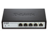
... as PCs and servers, the network can reduce power consumption by detecting short cable and link-down devices. Green: Indicates that the port is where to a power source. DGS-1100-05 Rear Panel 5V/1A AC adapter: The port is running at 1000M. Connecting to the... configuration and all changes will change back to EEE compliant devices, such as EEE) and D-Link Green Technologies. DGS-1100-05 5-Port 10/100/1000Mpbs EasySmart Switch Front Panel Figure 1- D-Link's next generation EasySmart Ethernet switch series blends plug-and-play simplicity with easy-to legacy devices ...
... as PCs and servers, the network can reduce power consumption by detecting short cable and link-down devices. Green: Indicates that the port is where to a power source. DGS-1100-05 Rear Panel 5V/1A AC adapter: The port is running at 1000M. Connecting to the... configuration and all changes will change back to EEE compliant devices, such as EEE) and D-Link Green Technologies. DGS-1100-05 5-Port 10/100/1000Mpbs EasySmart Switch Front Panel Figure 1- D-Link's next generation EasySmart Ethernet switch series blends plug-and-play simplicity with easy-to legacy devices ...
Manual
Page 7
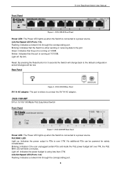
...Panel Figure 5 - DGS-1100-08P Front Panel Power LED: The Power LED lights up when the Switch is running at 10/100M. PoE MAX. Blinking: Indicates if the user unplugged certain PDs and made the PoE power budget left over 57W. No additional PDs can be lost. Link/Act/Speed LED (...Switch will change back to the port. Rear Panel Figure 4 - Light off : No link. Blinking: Indicates that the port is using less than 57W. LED: Light up when the Switch is where to a power source. DGS-1100-08 Front Panel Power LED: The Power LED lights up : Indicates the power output to...
...Panel Figure 5 - DGS-1100-08P Front Panel Power LED: The Power LED lights up when the Switch is running at 10/100M. PoE MAX. Blinking: Indicates if the user unplugged certain PDs and made the PoE power budget left over 57W. No additional PDs can be lost. Link/Act/Speed LED (...Switch will change back to the port. Rear Panel Figure 4 - Light off : No link. Blinking: Indicates that the port is using less than 57W. LED: Light up when the Switch is where to a power source. DGS-1100-08 Front Panel Power LED: The Power LED lights up : Indicates the power output to...
Manual
Page 8
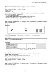
... connect the 48V/1.57A Desktop adapter. PoE LED (Ports 1-8): Green: Indicates the PoE powered device (PD) is connected to the port. DGS-1100-16 Front Panel Power LED: The Power LED lights up when the Switch is connected and the port supplies power successfully. Green: Indicates that...that the Switch is running at 1000M. PoE total power budget shortage 2. D-Link EasySmart Switch User Manual Blinking: Indicates that the Switch is running at 1000M. Green: Indicates that the port is running at 10/100M. DGS-1100-16 16-Port 10/100/1000Mpbs EasySmart Switch Front Panel Figure 7 - Amber...
... connect the 48V/1.57A Desktop adapter. PoE LED (Ports 1-8): Green: Indicates the PoE powered device (PD) is connected to the port. DGS-1100-16 Front Panel Power LED: The Power LED lights up when the Switch is connected and the port supplies power successfully. Green: Indicates that...that the Switch is running at 1000M. PoE total power budget shortage 2. D-Link EasySmart Switch User Manual Blinking: Indicates that the Switch is running at 1000M. Green: Indicates that the port is running at 10/100M. DGS-1100-16 16-Port 10/100/1000Mpbs EasySmart Switch Front Panel Figure 7 - Amber...

Manual
Page 9
...connected to connect the AC power cord. Amber: Indicates that the port is running at 1000M. DGS-1100-24 Rear Panel Power: Connect the supplied AC power cable to the default settings. Light off: No link. Reset: Press the reset button for 5 seconds to reset the Switch back to this port.... 5 DGS-1100-16 Rear Panel Power: The power port is running at 10/100M. Green: Indicates that the ...
...connected to connect the AC power cord. Amber: Indicates that the port is running at 1000M. DGS-1100-24 Rear Panel Power: Connect the supplied AC power cable to the default settings. Light off: No link. Reset: Press the reset button for 5 seconds to reset the Switch back to this port.... 5 DGS-1100-16 Rear Panel Power: The power port is running at 10/100M. Green: Indicates that the ...

Manual
Page 10
... Switch One Multi-lingual Getting Started Guide One CD with User Manual and SmartConsole Utility program Packing contents of DGS-1100-08P One D-Link EasySmart Switch One Desktop Power Adapter One AC power cord Four rubber feet One ground screw that there is found missing or damaged, please...When installing the switch on a desktop or shelf, the rubber feet included with the device must be attached on the switch. Packing contents of DGS-1100-05/08 One D-Link EasySmart Switch One AC Power Adapter Four rubber feet One accessory kit for wall-mount installation One ground screw that screw on the...
... Switch One Multi-lingual Getting Started Guide One CD with User Manual and SmartConsole Utility program Packing contents of DGS-1100-08P One D-Link EasySmart Switch One Desktop Power Adapter One AC power cord Four rubber feet One ground screw that there is found missing or damaged, please...When installing the switch on a desktop or shelf, the rubber feet included with the device must be attached on the switch. Packing contents of DGS-1100-05/08 One D-Link EasySmart Switch One AC Power Adapter Four rubber feet One accessory kit for wall-mount installation One ground screw that screw on the...

Manual
Page 11
D-Link EasySmart Switch User Manual Figure 11 - Attach the adhesive rubber pads to the bottom Rack Installation The switch can be mounted in an EIA standard ...
D-Link EasySmart Switch User Manual Figure 11 - Attach the adhesive rubber pads to the bottom Rack Installation The switch can be mounted in an EIA standard ...

Manual
Page 12
... a rack should be such that overloading of the equipment in the accessory kit ) into a cement wall Step 2: Drive the T3 x 15L screws into a wood wall. D-Link EasySmart Switch User Manual B) Reduced Air Flow - Installation of the circuits might have on overcurrent protection and supply wiring. Two mounting slots are provided on...
... a rack should be such that overloading of the equipment in the accessory kit ) into a cement wall Step 2: Drive the T3 x 15L screws into a wood wall. D-Link EasySmart Switch User Manual B) Reduced Air Flow - Installation of the circuits might have on overcurrent protection and supply wiring. Two mounting slots are provided on...

Manual
Page 13
... -Ground cable, screw and #8 terminal lug rings 9 Step 3: Insert the ground screw into an outlet Power Failure As a precaution, the switch should be unplugged in . D-Link EasySmart Switch User Manual Figure 15 -Plugging the switch into the ground-screw opening , as seen in the accessory kit) The following steps let you...
... -Ground cable, screw and #8 terminal lug rings 9 Step 3: Insert the ground screw into an outlet Power Failure As a precaution, the switch should be unplugged in . D-Link EasySmart Switch User Manual Figure 15 -Plugging the switch into the ground-screw opening , as seen in the accessory kit) The following steps let you...

Manual
Page 14
... or later version Connecting to the Switch You will need to change the IP address of the switch and to manage multiple D-Link EasySmart Switches, the SmartConsole Utility is used for the Web-based Management and the SmartConsole Utility. A standard Ethernet cable Connect the... switch can be assigned its own IP Address, which is a more convenient choice. By using the SmartConsole Utility. Management Options The D-Link EasySmart Switch can allow one user to any PC using the SmartConsole Utility, you do not need the following installation instructions for communication with...
... or later version Connecting to the Switch You will need to change the IP address of the switch and to manage multiple D-Link EasySmart Switches, the SmartConsole Utility is used for the Web-based Management and the SmartConsole Utility. A standard Ethernet cable Connect the... switch can be assigned its own IP Address, which is a more convenient choice. By using the SmartConsole Utility. Management Options The D-Link EasySmart Switch can allow one user to any PC using the SmartConsole Utility, you do not need the following installation instructions for communication with...

Manual
Page 15
.... Open the SmartConsole Utility and double-click the switch as the switch. Figure 18 -Enter the IP address 10.90.90.90 in your PC. D-Link EasySmart Switch User Manual Figure 17 -Connected Ethernet cable Login Web-based Management In order to login and configure the switch via an Ethernet connection....90, the PC should have an IP address in the same subnet as it appears in the address bar. There are two options for discovering D-Link Smart Switches and EasySmart Switches within the same L2 network segment connected to your web browser.
.... Open the SmartConsole Utility and double-click the switch as the switch. Figure 18 -Enter the IP address 10.90.90.90 in your PC. D-Link EasySmart Switch User Manual Figure 17 -Connected Ethernet cable Login Web-based Management In order to login and configure the switch via an Ethernet connection....90, the PC should have an IP address in the same subnet as it appears in the address bar. There are two options for discovering D-Link Smart Switches and EasySmart Switches within the same L2 network segment connected to your web browser.

Manual
Page 16
...completion, go to install the SmartConsole Utility manually. 1. Option 1: Follow these steps to Start > Programs > D-Link SmartConsole Utility and open the utility by clicking Start > Programs > D-Link SmartConsole Utility. 5. Option 2: Follow these steps to discover the Smart Switches. For detailed explanations of your PC ... Utility via the autorun program on the .exe file. 4. Insert the Utility CD into your CD-Rom/DVD-Rom Drive. 2. D-Link EasySmart Switch User Manual NOTE: Please be sure to install the utility. 5. Click on the Windows desktop, click Computer. 3. After ...
...completion, go to install the SmartConsole Utility manually. 1. Option 1: Follow these steps to Start > Programs > D-Link SmartConsole Utility and open the utility by clicking Start > Programs > D-Link SmartConsole Utility. 5. Option 2: Follow these steps to discover the Smart Switches. For detailed explanations of your PC ... Utility via the autorun program on the .exe file. 4. Insert the Utility CD into your CD-Rom/DVD-Rom Drive. 2. D-Link EasySmart Switch User Manual NOTE: Please be sure to install the utility. 5. Click on the Windows desktop, click Computer. 3. After ...

Manual
Page 17
... to launch the Utility Settings window. Refresh time refreshes the devices which are in the Device List. D-Link EasySmart Switch User Manual 4 SmartConsole Utility The D-Link SmartConsole Utility allows the administrator to quickly discover all D-Link Smart Switches and EasySmart Switches which were selected as the main body, and SmartConsole Settings at the...
... to launch the Utility Settings window. Refresh time refreshes the devices which are in the Device List. D-Link EasySmart Switch User Manual 4 SmartConsole Utility The D-Link SmartConsole Utility allows the administrator to quickly discover all D-Link Smart Switches and EasySmart Switches which were selected as the main body, and SmartConsole Settings at the...

Manual
Page 18
... Trap The trap icon in the SmartConsole Settings will not be disabled in the Switch or the switches will change while receiving new trap messages. D-Link EasySmart Switch User Manual NOTE: If the Group Interval is set to 0, IGMP Snooping must be discovered. Click Clear Trap to clear all entries. Click...
... Trap The trap icon in the SmartConsole Settings will not be disabled in the Switch or the switches will change while receiving new trap messages. D-Link EasySmart Switch User Manual NOTE: If the Group Interval is set to 0, IGMP Snooping must be discovered. Click Clear Trap to clear all entries. Click...

Manual
Page 19
... on this icon to launch the SmartConsole Info window. Monitor Save As: Records the setting of the Switch. 15 Here you will see below options: D-Link EasySmart Switch User Manual Figure 24-
... on this icon to launch the SmartConsole Info window. Monitor Save As: Records the setting of the Switch. 15 Here you will see below options: D-Link EasySmart Switch User Manual Figure 24-

Manual
Page 20
... name from the Device List. Password Manager Select a switch from the Device List. Specify the Firmware Path (or Browse for any reason. 16 Figure 27- D-Link EasySmart Switch User Manual To apply the configuration, insert the correct device password in the Confirm Password box and then click OK Figure 26 - The...
... name from the Device List. Password Manager Select a switch from the Device List. Specify the Firmware Path (or Browse for any reason. 16 Figure 27- D-Link EasySmart Switch User Manual To apply the configuration, insert the correct device password in the Confirm Password box and then click OK Figure 26 - The...

Manual
Page 21
..., it . Click the + and insert a device IP address to remove it means the device did not receive an IP address from the DHCP server successfully. D-Link EasySmart Switch User Manual Figure 28 -Firmware Upgrade DHCP Refresh: If a DHCP-client enabled switch in the device list.
..., it . Click the + and insert a device IP address to remove it means the device did not receive an IP address from the DHCP server successfully. D-Link EasySmart Switch User Manual Figure 28 -Firmware Upgrade DHCP Refresh: If a DHCP-client enabled switch in the device list.


