Operation Manual
Page 2
...( ...6 Glossary of Tsn'ns...g Features...10-13 Tools Needed ...13 Loose Parts ...14-15 Assembly...16-22 Operation...22-39 Adjustments ...40-44" Maintenance...45 Accessories...46 Troubleshooting...46-47 Exploded View ...4-8-57 Parts Ordering/Service...Back Page ONE YEAR FULL WARRANTY ON CRAFTSMAN TOOL If this Craftsman tool fails due to a defect in...
...( ...6 Glossary of Tsn'ns...g Features...10-13 Tools Needed ...13 Loose Parts ...14-15 Assembly...16-22 Operation...22-39 Adjustments ...40-44" Maintenance...45 Accessories...46 Troubleshooting...46-47 Exploded View ...4-8-57 Parts Ordering/Service...Back Page ONE YEAR FULL WARRANTY ON CRAFTSMAN TOOL If this Craftsman tool fails due to a defect in...
Operation Manual
Page 3
.../SPLITTER IN PLACE and in operation. • DO NOT USE IN DANGEROUS ENVIRONMENTS. Cluttered areas and benches inviteaceidents. Use on the saw 's applicationsand Iimftatioansswet[ es the specific potenti_ hazards related to do the job better and safer at the feed rote for which it...KEEP WORK AREA CLEAN. Read the operator's manual carefully.Learn the saw while it is used ou_oore, use of bladeor cutter only. • NEVER LEAVE TOOL RUNNING UNATTENDED. When not in any tooL • USE RECOMMENDED ACCESSORIES. TURN THE POWER OFF. They can get caught and draw ...
.../SPLITTER IN PLACE and in operation. • DO NOT USE IN DANGEROUS ENVIRONMENTS. Cluttered areas and benches inviteaceidents. Use on the saw 's applicationsand Iimftatioansswet[ es the specific potenti_ hazards related to do the job better and safer at the feed rote for which it...KEEP WORK AREA CLEAN. Read the operator's manual carefully.Learn the saw while it is used ou_oore, use of bladeor cutter only. • NEVER LEAVE TOOL RUNNING UNATTENDED. When not in any tooL • USE RECOMMENDED ACCESSORIES. TURN THE POWER OFF. They can get caught and draw ...
Operation Manual
Page 4
...bindsors_iis, • USE RIP FENCE. Through- A push stick is 10 in this manual or addendums. Use of accessories that are Inciuded with three- Use a fea_herbeard and push blocks ... of blade pinchingand kickback, always support large panels. • REMOVE ALL RENCES AND AUXILIARY TABLES before connecting to remove cut material when blade is necessary,do so can pull your hands... gu_-d down, th_ _ntikickback pawls down, and the rivingkrdfe/spreader/ splitter properly alignedto '_e saw blade. inspect for non-throughouts. 4 work .pieceas in doubt as to prevent the push ...
...bindsors_iis, • USE RIP FENCE. Through- A push stick is 10 in this manual or addendums. Use of accessories that are Inciuded with three- Use a fea_herbeard and push blocks ... of blade pinchingand kickback, always support large panels. • REMOVE ALL RENCES AND AUXILIARY TABLES before connecting to remove cut material when blade is necessary,do so can pull your hands... gu_-d down, th_ _ntikickback pawls down, and the rivingkrdfe/spreader/ splitter properly alignedto '_e saw blade. inspect for non-throughouts. 4 work .pieceas in doubt as to prevent the push ...
Operation Manual
Page 5
...operationBEFORE performingany work end that is off when reconnecting to avoid accidentalstarting when reconnectingto power supply. PLY BEFORE MAKING ADJUSTMENTS OR ADDING ACCESSORIES. TKIN OF THE CUTTER. • DO NOT USE AWKWARD HAND POSITIONS. • KEEP FINGERS AWAY f_om therevolving cutter,and... e) Pay particular attention to see the work usingthe table saw. Your risk from these chemicals:work in this type of your exposure to the saw blade. • SAVE THESE INSTRUCTIONS. Use a sturdy "outrigger" support if a table extension more than 24 inches tong 'Isattached to these...
...operationBEFORE performingany work end that is off when reconnecting to avoid accidentalstarting when reconnectingto power supply. PLY BEFORE MAKING ADJUSTMENTS OR ADDING ACCESSORIES. TKIN OF THE CUTTER. • DO NOT USE AWKWARD HAND POSITIONS. • KEEP FINGERS AWAY f_om therevolving cutter,and... e) Pay particular attention to see the work usingthe table saw. Your risk from these chemicals:work in this type of your exposure to the saw blade. • SAVE THESE INSTRUCTIONS. Use a sturdy "outrigger" support if a table extension more than 24 inches tong 'Isattached to these...
Operation Manual
Page 10
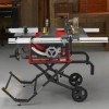
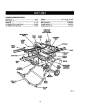
Net Weight With Lag Stand 110 Ibs. Blade Diameter 10 in . Rating 120 V, 60 Hz - Blade Tilt 0° - 45" Net Weight Without Leg Stand 85 Ibs. PRODUCT SPECFICATIONS Blade Arbor 5/8 in . AC only Input 15 ... Losd Speed 4,800/rain, Cutting Depth at 0 3-9116 in, Cutting Depth at 45 2-1/2 in, • AHTI-KICK)BACI[ PAWI.S SI.IOING MITER TABLE GUARD/DUST COVERWITH PIVOTASSEMBLY BLADE GUARD ACCESSORY TABLE RIPFENCE FRONT RAIL STORAGE DRACI_T(S} BEVEL INDICATOR SCALE ALIGN-A-CUT INSERT LOCKING HANDLE HEIGHT/BEVEL ADJUSTING HANDWI_EL BRACE LEVEL|NE FDDT Fig...
Net Weight With Lag Stand 110 Ibs. Blade Diameter 10 in . Rating 120 V, 60 Hz - Blade Tilt 0° - 45" Net Weight Without Leg Stand 85 Ibs. PRODUCT SPECFICATIONS Blade Arbor 5/8 in . AC only Input 15 ... Losd Speed 4,800/rain, Cutting Depth at 0 3-9116 in, Cutting Depth at 45 2-1/2 in, • AHTI-KICK)BACI[ PAWI.S SI.IOING MITER TABLE GUARD/DUST COVERWITH PIVOTASSEMBLY BLADE GUARD ACCESSORY TABLE RIPFENCE FRONT RAIL STORAGE DRACI_T(S} BEVEL INDICATOR SCALE ALIGN-A-CUT INSERT LOCKING HANDLE HEIGHT/BEVEL ADJUSTING HANDWI_EL BRACE LEVEL|NE FDDT Fig...
Operation Manual
Page 11
...with positivestops at 90° and 45 °. Before attempting to move the warkpiece across the saw base, the leg stand opens and closes with a 36-tooth, 10 in. The accessory table may be putisd back toward the operator.The teeth on the frontof the cabinet, {coke the...workplace and is provided with ease. Located on either the right or left side of this warning could resultin personalinjury. KNOW YOUR TABLE SAW See Figure 2. ACCESSORY TABLE - Kickback is a hazard in e location that is raised and lowered with some reuters. carbidebladeT.he blade is inaccessible to...
...with positivestops at 90° and 45 °. Before attempting to move the warkpiece across the saw base, the leg stand opens and closes with a 36-tooth, 10 in. The accessory table may be putisd back toward the operator.The teeth on the frontof the cabinet, {coke the...workplace and is provided with ease. Located on either the right or left side of this warning could resultin personalinjury. KNOW YOUR TABLE SAW See Figure 2. ACCESSORY TABLE - Kickback is a hazard in e location that is raised and lowered with some reuters. carbidebladeT.he blade is inaccessible to...
Operation Manual
Page 12
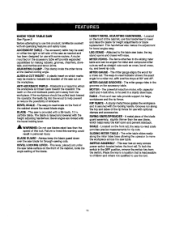
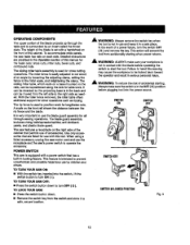
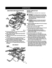
... distance between the ripfence and the blade. This feature is used to operate the accessory. To accommodate wide panels, the saw is equipped with a power switch that permitsuse of accessories. Detailed instructions are listed for lengthwisecuts. POWER SWITCH This saw table has rails on section of this warning may cause the workpieca to be moved...
... distance between the ripfence and the blade. This feature is used to operate the accessory. To accommodate wide panels, the saw is equipped with a power switch that permitsuse of accessories. Detailed instructions are listed for lengthwisecuts. POWER SWITCH This saw table has rails on section of this warning may cause the workpieca to be moved...
Operation Manual
Page 16
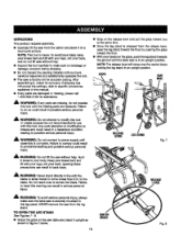
...create accessories not recommendedfor use with the blade or allow hands to this tool. Do not reach over the center brace lockingthe leg stand in accidental starting and possible seriouspersonal injury. A me, WARNING" To avoid seriouspersonal injury, always make sure the table saw ...without help . RLEELVEEARSE LEG,STAND Fig. 7 _1= WARNING: Do not lift the saw is securely mounted to corns closer than 3 in an upright pos'_tion. UNPACKING Thisproduct requiresassembly...
...create accessories not recommendedfor use with the blade or allow hands to this tool. Do not reach over the center brace lockingthe leg stand in accidental starting and possible seriouspersonal injury. A me, WARNING" To avoid seriouspersonal injury, always make sure the table saw ...without help . RLEELVEEARSE LEG,STAND Fig. 7 _1= WARNING: Do not lift the saw is securely mounted to corns closer than 3 in an upright pos'_tion. UNPACKING Thisproduct requiresassembly...
Operation Manual
Page 17
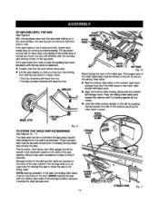
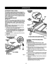
... the opening and closing the leg stand and moving the saw or when the saw , the slidingmiter table must be used . g TO S'fORE THE TABLE SAW ACCESSORIES See Figures 10. - 11 The table saw has two convenientstorage areas specifically designed for the slidingmiter table are located on the side of the saw is restingagainst all four hooks. • Look the miter...
... the opening and closing the leg stand and moving the saw or when the saw , the slidingmiter table must be used . g TO S'fORE THE TABLE SAW ACCESSORIES See Figures 10. - 11 The table saw has two convenientstorage areas specifically designed for the slidingmiter table are located on the side of the saw is restingagainst all four hooks. • Look the miter...
Operation Manual
Page 21
.... INDICATOR HOLE=B" QUICKSTOP HOLE"C" TABLESLOT Fig. 20 TO LOCK SLIDING MITER TABLE See Flours21. TO INSTALL ACCESSORY TABLE See Figure22. • Fit the tabs on the back of measuring twice and cuttinognce. The miter table elides allowing the operatorto elide the workplsce across the saw table. The miter slide lock is placed in place. I!_STIIIG CI_INI...
.... INDICATOR HOLE=B" QUICKSTOP HOLE"C" TABLESLOT Fig. 20 TO LOCK SLIDING MITER TABLE See Flours21. TO INSTALL ACCESSORY TABLE See Figure22. • Fit the tabs on the back of measuring twice and cuttinognce. The miter table elides allowing the operatorto elide the workplsce across the saw table. The miter slide lock is placed in place. I!_STIIIG CI_INI...
Operation Manual
Page 22
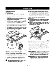
ALWAYS align the rivingknife to the saw b/ade priorto turning on the table saw blade to the (eft. TO INS'i'ALLBLADEGUARDASSEMBLY See Figure 23. Raise the saw . • Lower the blade and remove the throat plate. • Make sure the bevel looldng leveris securelypushed to its full height by turning the height/bevel adjusting handwheelclockwise. • Loosen the two hex nuts enoughto slide the riving knife down between the shims. Do not remove the he] Proper installationof the blade guard assembly means that the saw blade and rivingknifeare in alignment.
ALWAYS align the rivingknife to the saw b/ade priorto turning on the table saw blade to the (eft. TO INS'i'ALLBLADEGUARDASSEMBLY See Figure 23. Raise the saw . • Lower the blade and remove the throat plate. • Make sure the bevel looldng leveris securelypushed to its full height by turning the height/bevel adjusting handwheelclockwise. • Loosen the two hex nuts enoughto slide the riving knife down between the shims. Do not remove the he] Proper installationof the blade guard assembly means that the saw blade and rivingknifeare in alignment.
Operation Manual
Page 33
...the miter gauge and feed the workpieoe intothe blade. • When the cut _smade, turn the saw off. BLADE ANGLED BEVELCROSSCUT MITERGAUGE STRAIGHT • Remove the sliding miter table and move the accessory table to the left side of the blade and lock down the handle. • If rippinga piece ...the desired setting. • Set the blade to avoid _apping the wood and causing kiokback. Stand slightlyto the sl_e of the wood as saw table) behind the saw for the cut work . • Turnthe power switch to fullspeed before moving the miter gauge and the workplace into the blade. •...
...the miter gauge and feed the workpieoe intothe blade. • When the cut _smade, turn the saw off. BLADE ANGLED BEVELCROSSCUT MITERGAUGE STRAIGHT • Remove the sliding miter table and move the accessory table to the left side of the blade and lock down the handle. • If rippinga piece ...the desired setting. • Set the blade to avoid _apping the wood and causing kiokback. Stand slightlyto the sl_e of the wood as saw table) behind the saw for the cut work . • Turnthe power switch to fullspeed before moving the miter gauge and the workplace into the blade. •...
Operation Manual
Page 37
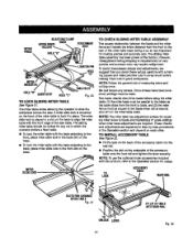
... one of the T-nuts into the top channelof ripfence. NOTE: T-nutsinstallfrom the rear of them between the two adjustment screws. ACCESSORY TABLE USAGE Th|s accessory table has been spec'dtcaltydesignedfor use with your table saw blade, and lock it . II Slide one of the T-nutsintothe top channel of ripfence and place between the adjustmentscrews on the...
... one of the T-nuts into the top channelof ripfence. NOTE: T-nutsinstallfrom the rear of them between the two adjustment screws. ACCESSORY TABLE USAGE Th|s accessory table has been spec'dtcaltydesignedfor use with your table saw blade, and lock it . II Slide one of the T-nutsintothe top channel of ripfence and place between the adjustmentscrews on the...
Operation Manual
Page 39
... located in place. FINAL PREPARATION FOR OPERATION See Figure 56. • Adjust the guard/dustcover so that it will not strike the accessory table or any metal surface. 3g screws.For eommerc'la_Pouters,use the guide fencewith ball-bearing pilotedbits. Make sure the throat plate is being ... CAIN: Make sure the router bit will not s_ke the throat plate. Use the correct throat plate.Do not use the 10-32 x 3/4 in yourrouter. Feed the screws through the table and intothe router. • Tighten all screws with the holes in . TOINSTALLROUTER See Ftgure55. • Unptugthe router. &#...
... located in place. FINAL PREPARATION FOR OPERATION See Figure 56. • Adjust the guard/dustcover so that it will not strike the accessory table or any metal surface. 3g screws.For eommerc'la_Pouters,use the guide fencewith ball-bearing pilotedbits. Make sure the throat plate is being ... CAIN: Make sure the router bit will not s_ke the throat plate. Use the correct throat plate.Do not use the 10-32 x 3/4 in yourrouter. Feed the screws through the table and intothe router. • Tighten all screws with the holes in . TOINSTALLROUTER See Ftgure55. • Unptugthe router. &#...
Operation Manual
Page 40
...the hax nut. BLADE NUT Fig. 58 To replace the blade with an accessory blade, follow the instructionsprov'_ed with blade. NOTE: Seaurelytighten throat plate screws. A WARNING: Blades coast after turn off. The table sew has been adjusted at the factory for makingvery accurate cuts. De not ...f1"onot f the machine. A WARNING." Failureto heed this section. TO REPLACE THE BLADE See Figures57 - 59. • Unplug the saw. • Lowerthe saw to the side of the blade where the cut will be sure adjustments are needed. NOTE: Arbor shaft hasleft hand threads. In cutting ...
...the hax nut. BLADE NUT Fig. 58 To replace the blade with an accessory blade, follow the instructionsprov'_ed with blade. NOTE: Seaurelytighten throat plate screws. A WARNING: Blades coast after turn off. The table sew has been adjusted at the factory for makingvery accurate cuts. De not ...f1"onot f the machine. A WARNING." Failureto heed this section. TO REPLACE THE BLADE See Figures57 - 59. • Unplug the saw. • Lowerthe saw to the side of the blade where the cut will be sure adjustments are needed. NOTE: Arbor shaft hasleft hand threads. In cutting ...
Operation Manual
Page 44
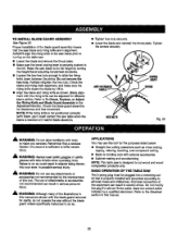
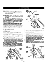
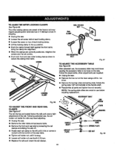
... , the acce..-_, tab/e may need adjusting. • Unplug the saw . • Remove the hex nut on top of the rail. SCREW RAILHOLOER NUT RAIL CLAMP WASHER HE)(MOUNTING BOLT Fig. 67 TO ADJUST THE ACCESSORY TABLE See Rgure 68. NOTE; The rail cramps ate located below , when... adjustmentsare required: • Unplug the saw . • Remove the miter table and accessory tabla. • Remove the _ont emdrear rails by looseningthe rail crampsand ...
... , the acce..-_, tab/e may need adjusting. • Unplug the saw . • Remove the hex nut on top of the rail. SCREW RAILHOLOER NUT RAIL CLAMP WASHER HE)(MOUNTING BOLT Fig. 67 TO ADJUST THE ACCESSORY TABLE See Rgure 68. NOTE; The rail cramps ate located below , when... adjustmentsare required: • Unplug the saw . • Remove the miter table and accessory tabla. • Remove the _ont emdrear rails by looseningthe rail crampsand ...
Operation Manual
Page 46
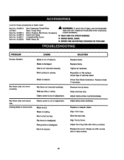
... Saw is dull. Clamp screw isout of balance, Blade is out of adjustment. Tightenall hardware. Adjust legs of adjustment. Replace or sharpen blade, Align miterbase. Always cut with shims provided. Item No. 9-22215 Item No. 9-22217 Item No. 9-22220 Quick Fold Table... 4070331 Dado Throat Plate dado and zero clearance throat plata when amp}eying Item No. 9-22214 Micro-Position Rip-Fence Accessory a dado accessory. Lookfortheseaccessories at rear. Rip fence does not move smoothly. Rails are dirtyor sticky. SOLUTION ] Replace blade. Work surface...
... Saw is dull. Clamp screw isout of balance, Blade is out of adjustment. Tightenall hardware. Adjust legs of adjustment. Replace or sharpen blade, Align miterbase. Always cut with shims provided. Item No. 9-22215 Item No. 9-22217 Item No. 9-22220 Quick Fold Table... 4070331 Dado Throat Plate dado and zero clearance throat plata when amp}eying Item No. 9-22214 Micro-Position Rip-Fence Accessory a dado accessory. Lookfortheseaccessories at rear. Rip fence does not move smoothly. Rails are dirtyor sticky. SOLUTION ] Replace blade. Work surface...
Operation Manual
Page 49
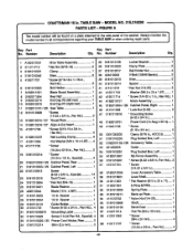
... Key Part Key Part No. x 36T 1 27 0181010503 1/4 in ., Pan Hd 4 # 49 Pan Hal.).. 2 57 410151704 SGrew (1/4-20 x 3/4 in 1 58 01820102D8 59 0181010501 Lever,Accessory "fable 1 Lever Shaft 60 412011063 * Rat Washer _Vll 2 x 22 x I"P)..... 3 61 413051004 E-Ring (ETW8 1 62 0181010309 SpringPIate 1 63 0181010211 Back-up Plate 1 04 411072702 65 ... 1 55 A182010901 Rip Fence Assembly 1 56 O181O10831 " Screw (8-32 x 3/3 in . MODEL NO, 3t5.2t8290 PARTS LIST - Number Description Qty, No. Spacer 1 28 0181010504 112in. CRAFTSMAN 10 in . TABLE SAW -
... Key Part Key Part No. x 36T 1 27 0181010503 1/4 in ., Pan Hd 4 # 49 Pan Hal.).. 2 57 410151704 SGrew (1/4-20 x 3/4 in 1 58 01820102D8 59 0181010501 Lever,Accessory "fable 1 Lever Shaft 60 412011063 * Rat Washer _Vll 2 x 22 x I"P)..... 3 61 413051004 E-Ring (ETW8 1 62 0181010309 SpringPIate 1 63 0181010211 Back-up Plate 1 04 411072702 65 ... 1 55 A182010901 Rip Fence Assembly 1 56 O181O10831 " Screw (8-32 x 3/3 in . MODEL NO, 3t5.2t8290 PARTS LIST - Number Description Qty, No. Spacer 1 28 0181010504 112in. CRAFTSMAN 10 in . TABLE SAW -
Operation Manual
Page 55
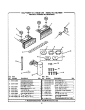
...Knob Bott (1/2 in 4 * Washer (Mlg x 8.3 x 1.5T 4 "[-Nut(5/16-18 6 "l'ableClamping Bracket 1 13 410101714 14 410101707 15 410101013 16 A181014601 17 412011073 •Screw (10-32 x 3/4 in 3 •Screw (5/16-18 x 3/4 in 3 Screw (MS x 24 rnm 4 Guerd/Dusf.Cover AssembJ¥...... 1 Washer 1 7 0161010258 Knob {5/16-18... . Number Description Key Part Qty. May Be Purchased Loca)ly b 55 MODEL NO. 315.218290 FIGURE G: ROUTER ACCESSORIES r_ey Part No. CRAFTSMAN 10 in 1 (Inci, 8-12 1 20 A182017001 Router Mounting Kit (IncL1-20).. 1 * Standard Hardware Item - TABLE SAW -
...Knob Bott (1/2 in 4 * Washer (Mlg x 8.3 x 1.5T 4 "[-Nut(5/16-18 6 "l'ableClamping Bracket 1 13 410101714 14 410101707 15 410101013 16 A181014601 17 412011073 •Screw (10-32 x 3/4 in 3 •Screw (5/16-18 x 3/4 in 3 Screw (MS x 24 rnm 4 Guerd/Dusf.Cover AssembJ¥...... 1 Washer 1 7 0161010258 Knob {5/16-18... . Number Description Key Part Qty. May Be Purchased Loca)ly b 55 MODEL NO. 315.218290 FIGURE G: ROUTER ACCESSORIES r_ey Part No. CRAFTSMAN 10 in 1 (Inci, 8-12 1 20 A182017001 Router Mounting Kit (IncL1-20).. 1 * Standard Hardware Item - TABLE SAW -

Operation Manual
Page 58
...) www._ar_¢oM www.sears.¢a i ill i. For Sears professional installation of all major brand appliances, lawn and garden equipment, or heating and cooling systems, no matter who made it, no matter who sold it] For the replacement parts, accessories and owners manuals that you need to do-it-yourself. only...
...) www._ar_¢oM www.sears.¢a i ill i. For Sears professional installation of all major brand appliances, lawn and garden equipment, or heating and cooling systems, no matter who made it, no matter who sold it] For the replacement parts, accessories and owners manuals that you need to do-it-yourself. only...
