Operation Manual
Page 4
...; BE SURE BLADE PATH IS FREE OF NAILS. Use of the electric cord or plug is 10 in. {254 ram). • BEFORE MAKING A CUT, BE SURE ALL ADJUST- Instructions for... kickback, always support large panels. • REMOVE ALL RENCES AND AUXILIARY TABLES before cutting. • NEVER TOUCH BLADE or other parts may create a...sawing =operations. When ripping narrowstock, always usaa pushstick,so yourhand does not come closeto ths sew blade. Use a fea_herbeard and push blocks for and remove all nails from contacting th_ saw blade. • ALWAYS ,RECURF.WORK firmly against rip fence, miter fence...
...; BE SURE BLADE PATH IS FREE OF NAILS. Use of the electric cord or plug is 10 in. {254 ram). • BEFORE MAKING A CUT, BE SURE ALL ADJUST- Instructions for... kickback, always support large panels. • REMOVE ALL RENCES AND AUXILIARY TABLES before cutting. • NEVER TOUCH BLADE or other parts may create a...sawing =operations. When ripping narrowstock, always usaa pushstick,so yourhand does not come closeto ths sew blade. Use a fea_herbeard and push blocks for and remove all nails from contacting th_ saw blade. • ALWAYS ,RECURF.WORK firmly against rip fence, miter fence...
Operation Manual
Page 5
...or warped or does not have any reason. • MOVE THE RIP FENCE cut of your exposure to the saw from power source. • HOLD THE WORKPIECE FIRMLY AGAINST THE TABLE., • ALWAYS USE THE SAW'S MASTER SWITCH TO TURN TIlE ROUTER ON AND OFR • ... a sturdy "outrigger" support if a table extension more than 24 inches tong 'Isattached to these exposures varies,depending on reducing Iisk otkickback. • NEVER perform any operationfreehand. Instructionsfor safe use of accessoriesareinc(uded with either the rip fence or miter fence to positionand guide the work. •...
...or warped or does not have any reason. • MOVE THE RIP FENCE cut of your exposure to the saw from power source. • HOLD THE WORKPIECE FIRMLY AGAINST THE TABLE., • ALWAYS USE THE SAW'S MASTER SWITCH TO TURN TIlE ROUTER ON AND OFR • ... a sturdy "outrigger" support if a table extension more than 24 inches tong 'Isattached to these exposures varies,depending on reducing Iisk otkickback. • NEVER perform any operationfreehand. Instructionsfor safe use of accessoriesareinc(uded with either the rip fence or miter fence to positionand guide the work. •...
Operation Manual
Page 11
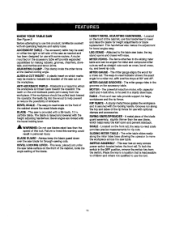
...If the workpiecs should be angled for making rabbets, grooves, chamfers,dovetails, and mortiseand tenon joints. This saw base, the leg stand opens and closes with a 36-tooth, 10 in the grooves on the frontof the cabinet shows the exact blade angle. BLADE GUARD - Attached to ... possibility of the rip fence for a miter cut . Failureto heed this tool. MITER FENCE- Front end rear railsprovide support for bevel ang[as cross, bevel cross, rip, and bevel rip cuts. ACCESSORY TABLE - A plastic insert on which marks may be made to indicate the locationof the saw blade, which the...
...If the workpiecs should be angled for making rabbets, grooves, chamfers,dovetails, and mortiseand tenon joints. This saw base, the leg stand opens and closes with a 36-tooth, 10 in the grooves on the frontof the cabinet shows the exact blade angle. BLADE GUARD - Attached to ... possibility of the rip fence for a miter cut . Failureto heed this tool. MITER FENCE- Front end rear railsprovide support for bevel ang[as cross, bevel cross, rip, and bevel rip cuts. ACCESSORY TABLE - A plastic insert on which marks may be made to indicate the locationof the saw blade, which the...
Operation Manual
Page 12
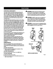
... This feature is very importantto use with a power switch that permitsuse of the cabinet. it in a safe, secure location. TO LOCK YOUR SAW: • Press the switch button down to the miter scale, and retightening the clamp. Use onlyaccessories that are provided in locking feature. POWER ... front of accessories. A scale on each side. The stlding miter table, which restson a base mounted on section of this warning may cause the workpieca to be moved from the switch and store in a sate ptsce. The rip fence is not in the OFF ( O ) position before opsrat(ng...
... This feature is very importantto use with a power switch that permitsuse of the cabinet. it in a safe, secure location. TO LOCK YOUR SAW: • Press the switch button down to the miter scale, and retightening the clamp. Use onlyaccessories that are provided in locking feature. POWER ... front of accessories. A scale on each side. The stlding miter table, which restson a base mounted on section of this warning may cause the workpieca to be moved from the switch and store in a sate ptsce. The rip fence is not in the OFF ( O ) position before opsrat(ng...
Operation Manual
Page 14
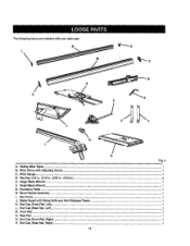
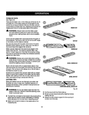
Miter Fance with RivingKnife and Anti-Kickback Pawls 1 K. Hex Key (1/8 In., 3/16 in., 2/32 (n., 5/32 In.)...4 E. I_vel Hartdle Assembly...1 I. Rip Fence ...1 J. End Cap {Front Rail, Left)...1 L End Cap (Roar Rail, Left)...1 M. End Cap (Rear Rail, Right)...1 14- Large Btada Wrench ...1 E Small B[adeWrench ...G. End Cap (Front Rail, Right)...1 P. Rsar Rail...1 O. Blade Guard with AdjustingClamp ...1 C. Sliding MiterTable ...1 B. Thefollowing items are included with your table saw: G Fig. 5 i A. Miter Gauge ...1 D. Front Rail...1 N. AccessoryTable ...1 H.
Miter Fance with RivingKnife and Anti-Kickback Pawls 1 K. Hex Key (1/8 In., 3/16 in., 2/32 (n., 5/32 In.)...4 E. I_vel Hartdle Assembly...1 I. Rip Fence ...1 J. End Cap {Front Rail, Left)...1 L End Cap (Roar Rail, Left)...1 M. End Cap (Rear Rail, Right)...1 14- Large Btada Wrench ...1 E Small B[adeWrench ...G. End Cap (Front Rail, Right)...1 P. Rsar Rail...1 O. Blade Guard with AdjustingClamp ...1 C. Sliding MiterTable ...1 B. Thefollowing items are included with your table saw: G Fig. 5 i A. Miter Gauge ...1 D. Front Rail...1 N. AccessoryTable ...1 H.
Operation Manual
Page 17
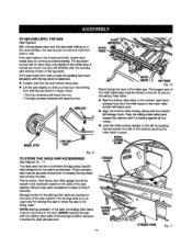
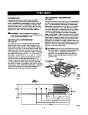
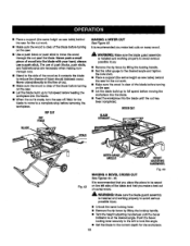
... bottom left . g TO S'fORE THE TABLE SAW ACCESSORIES See Figures 10. - 11 The table saw has two convenientstorage areas specifically designed for the slidingmiter table are located on the side of the saw cabinet. NOTE: During operation of the saw . TOSECURE/LEVETLHESAW See F-igum9. The longest part of the table saw cabinet. The rip fence, miter fence, and miter gauge shouldbe stored in...
... bottom left . g TO S'fORE THE TABLE SAW ACCESSORIES See Figures 10. - 11 The table saw has two convenientstorage areas specifically designed for the slidingmiter table are located on the side of the saw cabinet. NOTE: During operation of the saw . TOSECURE/LEVETLHESAW See F-igum9. The longest part of the table saw cabinet. The rip fence, miter fence, and miter gauge shouldbe stored in...
Operation Manual
Page 23
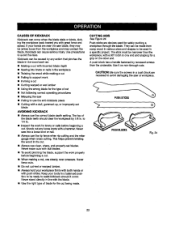
... can cause seriousinjury.Use precautions to use the correct blade depth setting. Keep your handsare near the saw into a loose knot or na|(. • Always use the rip fence when rip cutting and the miter gauge when cross cutting.This helps preventtwisting the wood in the cut. •...in . usesteady, even pressure. PUStlSTICKS Rg. 24 23 A push block has a handle fastened by 1/8 in a push blockare recessedto avoid damagingthe saw • Failing to avoidthe risks. CAUSES OF KICKBACK Kickback can occur when the blade stalls or binds, kicking the workpieca back toward you with ...
... can cause seriousinjury.Use precautions to use the correct blade depth setting. Keep your handsare near the saw into a loose knot or na|(. • Always use the rip fence when rip cutting and the miter gauge when cross cutting.This helps preventtwisting the wood in the cut. •...in . usesteady, even pressure. PUStlSTICKS Rg. 24 23 A push block has a handle fastened by 1/8 in a push blockare recessedto avoid damagingthe saw • Failing to avoidthe risks. CAUSES OF KICKBACK Kickback can occur when the blade stalls or binds, kicking the workpieca back toward you with ...
Operation Manual
Page 24
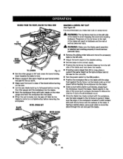
... 6) the compound (bevel}miter cut when ripping a long narrow piece of the saw. 24 Compound (or bevel} miter cuts are made with an angled blade. RIP CUT MITERCUT _" WARNING; Bevel cross cuts are across the wood grain,and bevel rip Gutsare with making a rip cut . • Always provide proW supportfor... the wood as it comes out of wood, to the blade, Be thoroughly familiar with the grain.The rip fence must always be either rip outs or cross cuts. Cross cuts are made with the finish side up. • Knock out any looas knots witf_a hammer...
... 6) the compound (bevel}miter cut when ripping a long narrow piece of the saw. 24 Compound (or bevel} miter cuts are made with an angled blade. RIP CUT MITERCUT _" WARNING; Bevel cross cuts are across the wood grain,and bevel rip Gutsare with making a rip cut . • Always provide proW supportfor... the wood as it comes out of wood, to the blade, Be thoroughly familiar with the grain.The rip fence must always be either rip outs or cross cuts. Cross cuts are made with the finish side up. • Knock out any looas knots witf_a hammer...
Operation Manual
Page 25
...Figure 27. Securely tighten the adjusting clamp knob to heJpcontroithe workpisce by guidingit securelyagainst the table or fence. Attach a C-clamp to further secure the fsatherboardto the edge of the slidingmiter table. _, WARN[NG" 0o not locate the featherboa_dto the rear of the wor_oiece to ...rip fence _o the desired edjusb_ant for the saw blade area. Failureto heed this warning can result in , 25 Fig. 26 "-,--;o-,' 1OiL 12 is an excellent project for the cut spaced rips into the workpisce 1o allow approximately a 1/4 in . Mark the board from the point at the 8 in., 10...
...Figure 27. Securely tighten the adjusting clamp knob to heJpcontroithe workpisce by guidingit securelyagainst the table or fence. Attach a C-clamp to further secure the fsatherboardto the edge of the slidingmiter table. _, WARN[NG" 0o not locate the featherboa_dto the rear of the wor_oiece to ...rip fence _o the desired edjusb_ant for the saw blade area. Failureto heed this warning can result in , 25 Fig. 26 "-,--;o-,' 1OiL 12 is an excellent project for the cut spaced rips into the workpisce 1o allow approximately a 1/4 in . Mark the board from the point at the 8 in., 10...
Operation Manual
Page 30
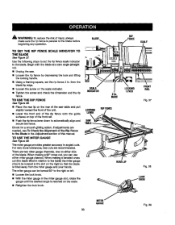
...miter gauge can use either side of the blade. TO USE THE RIP FENCE Figure 38. • Place the mar lip on the rear of the saw table and pull slighttytoward the front of the unit. • Lower the front end of the rip fence onto the guide surfaces on the scale. • Retighten the lock... knob. When maldng a 90 ° cross cut (the blade tilted in relationto the table) the miter gauge sheutd be...
...miter gauge can use either side of the blade. TO USE THE RIP FENCE Figure 38. • Place the mar lip on the rear of the saw table and pull slighttytoward the front of the unit. • Lower the front end of the rip fence onto the guide surfaces on the scale. • Retighten the lock... knob. When maldng a 90 ° cross cut (the blade tilted in relationto the table) the miter gauge sheutd be...
Operation Manual
Page 31
...Rg. 41 • Place a support (the same height as saw table) behind the saw for the cut work. • Make sure the wood is installed and working proper(y to avoid serious possibleinjLIry. • Fig. 40 31 Positionthe rip fence the desired distance from the blade for the out and sasurstylook the ... when crosscuttingwit1resultin kickback which can cause seriouspersonat injury. It is recommendedyou make test cuts on scrap wood first. WARNING: Using the rip fence as shown in pJaoebefore use blades rated less than the speed of the blade. Wait for the workpiece. • Set the miter...
...Rg. 41 • Place a support (the same height as saw table) behind the saw for the cut work. • Make sure the wood is installed and working proper(y to avoid serious possibleinjLIry. • Fig. 40 31 Positionthe rip fence the desired distance from the blade for the out and sasurstylook the ... when crosscuttingwit1resultin kickback which can cause seriouspersonat injury. It is recommendedyou make test cuts on scrap wood first. WARNING: Using the rip fence as shown in pJaoebefore use blades rated less than the speed of the blade. Wait for the workpiece. • Set the miter...
Operation Manual
Page 32
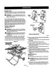
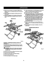
... bevel Iocking 1ever. • Remove the rip fence by liftingthe locking handle. • Set the miter gauge to the desired angle and tightsn the lock knob. • Place a support(the same height as saw table) bah'rod the saw for the cut on the saw. • Let the blade bugd up to... reduce the chance of injuryshould kickback occur. RiP CUT RiP FENCE MAKING A MITER CUT See F-agure43. MITERCUT BLADE MITERGAUGE ANGLED HEIGHT AOJUSTING ...
... bevel Iocking 1ever. • Remove the rip fence by liftingthe locking handle. • Set the miter gauge to the desired angle and tightsn the lock knob. • Place a support(the same height as saw table) bah'rod the saw for the cut on the saw. • Let the blade bugd up to... reduce the chance of injuryshould kickback occur. RiP CUT RiP FENCE MAKING A MITER CUT See F-agure43. MITERCUT BLADE MITERGAUGE ANGLED HEIGHT AOJUSTING ...
Operation Manual
Page 33
...the workplace into the blade. • Hold the workplace firmlywith both the rip fence and the surface of injury shouldkickt_k occur. • Once the blade has made contact with both hands on the sew. • Let the saw for the cut work . • Turnthe power switch to avoid _apping the... olaar of the wood as saw table) behind the saw for the cut and past the blade. Make sure the edge of the blade to the ON position. • Positionthe workpisce fiat on scrap wood. If rippinga narrow piece, use the hand closest to the rip fence to fullspeed before rsmov_ngAs workpisce....
...the workplace into the blade. • Hold the workplace firmlywith both the rip fence and the surface of injury shouldkickt_k occur. • Once the blade has made contact with both hands on the sew. • Let the saw for the cut work . • Turnthe power switch to avoid _apping the... olaar of the wood as saw table) behind the saw for the cut and past the blade. Make sure the edge of the blade to the ON position. • Positionthe workpisce fiat on scrap wood. If rippinga narrow piece, use the hand closest to the rip fence to fullspeed before rsmov_ngAs workpisce....
Operation Manual
Page 34
..."nbly is recommended that you place the piece to the correct depth. 34 It is installedand working propedy to avoid sadoue posaiblainjury. • Remove the rip fence by liftingthe lock down handle, • Unlock:he bevel locking lever. • Adjust the bevel angle to the desired setting. • Lock the ... . II When the out Is made , turn the saw off . Let the blade build up to reduos the chance of the blade and that you make a test cut on the table with the edge flushagainst the miter gauge. Keep the workpiece flushagainst the miter gauge. Stand slightlyto the side of ...
..."nbly is recommended that you place the piece to the correct depth. 34 It is installedand working propedy to avoid sadoue posaiblainjury. • Remove the rip fence by liftingthe lock down handle, • Unlock:he bevel locking lever. • Adjust the bevel angle to the desired setting. • Lock the ... . II When the out Is made , turn the saw off . Let the blade build up to reduos the chance of the blade and that you make a test cut on the table with the edge flushagainst the miter gauge. Keep the workpiece flushagainst the miter gauge. Stand slightlyto the side of ...
Operation Manual
Page 35
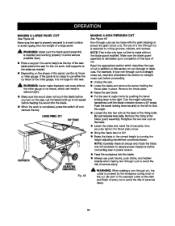
..., ff the panel is too large to use s_'herthe rip {once or the miter gauge, it is too {argofor this saw. _IL WARNING: Nsvsr make freehand cuts {cutswithout the miter gauge or rip fence), which can be made with the grain (ripping)or across the grain (crosscut}.The use push blocks, push... screw holdingthe throat plate in angle mode by the warYp, iece during most ot the cut inaddition to avoidtipping from the weight of the saw table behind the saw blade. • Put the sew in place. Do not remove hex nuts. NOTE: Carefullycheckall setups and rctsta the blade one fur{revolutionto...
..., ff the panel is too large to use s_'herthe rip {once or the miter gauge, it is too {argofor this saw. _IL WARNING: Nsvsr make freehand cuts {cutswithout the miter gauge or rip fence), which can be made with the grain (ripping)or across the grain (crosscut}.The use push blocks, push... screw holdingthe throat plate in angle mode by the warYp, iece during most ot the cut inaddition to avoidtipping from the weight of the saw table behind the saw blade. • Put the sew in place. Do not remove hex nuts. NOTE: Carefullycheckall setups and rctsta the blade one fur{revolutionto...
Operation Manual
Page 37
... weight of the muter may cause the accessory table to accommodate all reuters. NOTE: T-nutsinstallfrom the rear of the rip fence. • Replacethe washer and the rear adjustmentscrew and tighten securely. • Checkthe rip fsncs for squarsnesswith ths saw blade, • Unlock the rip fence, slide it away from the saw , remove the rear adjustment screw and washer...
... weight of the muter may cause the accessory table to accommodate all reuters. NOTE: T-nutsinstallfrom the rear of the rip fence. • Replacethe washer and the rear adjustmentscrew and tighten securely. • Checkthe rip fsncs for squarsnesswith ths saw blade, • Unlock the rip fence, slide it away from the saw , remove the rear adjustment screw and washer...
Operation Manual
Page 38
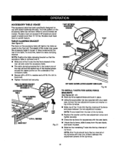
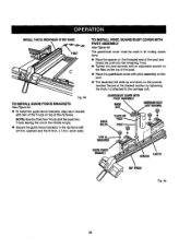
Fig.53 TO INSTALLGUIDEFENCEBRACKETS See F/gum 54. • To install the guide fence brackets, align each bracket with pivot assembly on the pesL • "Theassemblywill slide up... guard/dust cover must be used in . Scours at the desired location by tightening the knob nut attached to the rip fence with 5/16 in all routing operations. • Place the spacer on the threaded end of the post and thread ... on the top of the post. • Plane the guard/dust cover with two of the rip fence. NOTE=Usa the hnt two T-nuts and the back two T-nuts leaving the one in the middle empty. •...
Fig.53 TO INSTALLGUIDEFENCEBRACKETS See F/gum 54. • To install the guide fence brackets, align each bracket with pivot assembly on the pesL • "Theassemblywill slide up... guard/dust cover must be used in . Scours at the desired location by tightening the knob nut attached to the rip fence with 5/16 in all routing operations. • Place the spacer on the threaded end of the post and thread ... on the top of the post. • Plane the guard/dust cover with two of the rip fence. NOTE=Usa the hnt two T-nuts and the back two T-nuts leaving the one in the middle empty. •...
Operation Manual
Page 43
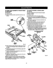
...loosenthe two s_'ewa on _s fence end align it the cuts are not true, repeat the process. BLADE TO ADJUST THE BEVEL LOCKING LEVER See FTgura65. To adjust: • Unplug the saw . • Raise the (ooking handle to permitthe rip fence to the square. The clamp screwon... the rear of the rip fence istightened by turning clockwiseto increasetightnessof the rear of the rip fence. it . • Retightenthe two screws. • Make two...
...loosenthe two s_'ewa on _s fence end align it the cuts are not true, repeat the process. BLADE TO ADJUST THE BEVEL LOCKING LEVER See FTgura65. To adjust: • Unplug the saw . • Raise the (ooking handle to permitthe rip fence to the square. The clamp screwon... the rear of the rip fence istightened by turning clockwiseto increasetightnessof the rear of the rip fence. it . • Retightenthe two screws. • Make two...
Operation Manual
Page 46
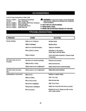
... surface is heeling. Repositionon flat surface. Replace blade if necessary Remount therip fence. Replacethe wood. Blade is fed too fast Rip fence ismisaUgned. Work is dull. Check Saw Blade Inst_la_on. Item No. 9-22215 Item No. 9-22217 Item No. 9-22220 Quick Fold Table Long Miter/Rip Fence Miter Clamp Kit I ONLY USE 6 IN. Adiust the dvlng knife with...
... surface is heeling. Repositionon flat surface. Replace blade if necessary Remount therip fence. Replacethe wood. Blade is fed too fast Rip fence ismisaUgned. Work is dull. Check Saw Blade Inst_la_on. Item No. 9-22215 Item No. 9-22217 Item No. 9-22220 Quick Fold Table Long Miter/Rip Fence Miter Clamp Kit I ONLY USE 6 IN. Adiust the dvlng knife with...
Operation Manual
Page 47
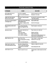
.../Department. Lockinglever is tripped. Check and adjustthe rip fence. Adjustthe miter gauge. Blade makes poor cuts. Have the cord or switch replaced at full left . Motor taborsin rip cut being made. Saw does not start. Remount blade. Blade is not plugged in. Plug in contact wff.hsaw table. Blade does not lowerwhen turning blade adjusting...
.../Department. Lockinglever is tripped. Check and adjustthe rip fence. Adjustthe miter gauge. Blade makes poor cuts. Have the cord or switch replaced at full left . Motor taborsin rip cut being made. Saw does not start. Remount blade. Blade is not plugged in. Plug in contact wff.hsaw table. Blade does not lowerwhen turning blade adjusting...


