Operation Manual
Page 2
...( ...6 Glossary of Tsn'ns...g Features...10-13 Tools Needed ...13 Loose Parts ...14-15 Assembly...16-22 Operation...22-39 Adjustments ...40-44" Maintenance...45 Accessories...46 Troubleshooting...46-47 Exploded View ...4-8-57 Parts Ordering/Service...Back Page ONE YEAR FULL WARRANTY ON CRAFTSMAN TOOL If this Craftsman tool fails due to a defect in...
...( ...6 Glossary of Tsn'ns...g Features...10-13 Tools Needed ...13 Loose Parts ...14-15 Assembly...16-22 Operation...22-39 Adjustments ...40-44" Maintenance...45 Accessories...46 Troubleshooting...46-47 Exploded View ...4-8-57 Parts Ordering/Service...Back Page ONE YEAR FULL WARRANTY ON CRAFTSMAN TOOL If this Craftsman tool fails due to a defect in...
Operation Manual
Page 3
...or attachment to determine that may resuttin electric shock, fire andlor serious personal injury. Read the operator's manual carefully.Learn the saw while it for better and safer performanca.FoJiow instructionsfor lubricatingand changingaccessories. • DISCONNECT TOOLS. Rubber glovesand nonskidfoo[wser are removedfrom ...hands to a complete stop, • PROTECT YOUR LUNGS. If in doubt, use it is in any tooL • USE RECOMMENDED ACCESSORIES. A guard or o_er part _at is unintention_lly con_.cted. • CHECK DAMAGED PARTS. They can get caught and draw you intomoving ...
...or attachment to determine that may resuttin electric shock, fire andlor serious personal injury. Read the operator's manual carefully.Learn the saw while it for better and safer performanca.FoJiow instructionsfor lubricatingand changingaccessories. • DISCONNECT TOOLS. Rubber glovesand nonskidfoo[wser are removedfrom ...hands to a complete stop, • PROTECT YOUR LUNGS. If in doubt, use it is in any tooL • USE RECOMMENDED ACCESSORIES. A guard or o_er part _at is unintention_lly con_.cted. • CHECK DAMAGED PARTS. They can get caught and draw you intomoving ...
Operation Manual
Page 4
... mum blade capacity of your saw . To minimize risk of blade pinchingand kickback, always support large panels. • REMOVE ALL RENCES AND AUXILIARY TABLES before connecting to remove cut ...clean- Failureto do not connect the equipment-grounding conductor to whether the tool is 10 in an accidsn.tcausing pose_le serious personalinjury. • ALWAYS USE BLADE GUARD, RMNG KNIFE/... .pieceas in this manual or addendums. Use of accessories that are tired. Normal sparking of cord location and keep itwen away from contacting th_ saw blade. • ALWAYS ,RECURF.WORK firmly against ...
... mum blade capacity of your saw . To minimize risk of blade pinchingand kickback, always support large panels. • REMOVE ALL RENCES AND AUXILIARY TABLES before connecting to remove cut ...clean- Failureto do not connect the equipment-grounding conductor to whether the tool is 10 in an accidsn.tcausing pose_le serious personalinjury. • ALWAYS USE BLADE GUARD, RMNG KNIFE/... .pieceas in this manual or addendums. Use of accessories that are tired. Normal sparking of cord location and keep itwen away from contacting th_ saw blade. • ALWAYS ,RECURF.WORK firmly against ...
Operation Manual
Page 5
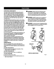
... TO TURN TIlE ROUTER ON AND OFR • THIS TOOL shouldhave the fo2low'_nmgarkings: a) Wear eye protection. d) Not retsasingthe work usingthe table saw blade. ROUTER ACCESSORY SAFETY RULES • ALWAYS DISCONNECT SAW FROM POWER SUP- g) Never reach around or over ,or within three inches of the blade or cutter with approved safety equipment, such...
... TO TURN TIlE ROUTER ON AND OFR • THIS TOOL shouldhave the fo2low'_nmgarkings: a) Wear eye protection. d) Not retsasingthe work usingthe table saw blade. ROUTER ACCESSORY SAFETY RULES • ALWAYS DISCONNECT SAW FROM POWER SUP- g) Never reach around or over ,or within three inches of the blade or cutter with approved safety equipment, such...
Operation Manual
Page 10
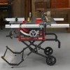
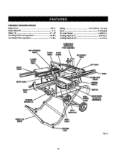
Blade Tilt 0° - 45" Net Weight Without Leg Stand 85 Ibs. Rating 120 V, 60 Hz - Blade Diameter 10 in , • AHTI-KICK)BACI[ PAWI.S SI.IOING MITER TABLE GUARD/DUST COVERWITH PIVOTASSEMBLY BLADE GUARD ACCESSORY TABLE RIPFENCE FRONT RAIL STORAGE DRACI_T(S} BEVEL INDICATOR SCALE ALIGN-A-CUT INSERT LOCKING HANDLE HEIGHT/BEVEL ADJUSTING HANDWI_EL BRACE LEVEL...
Blade Tilt 0° - 45" Net Weight Without Leg Stand 85 Ibs. Rating 120 V, 60 Hz - Blade Diameter 10 in , • AHTI-KICK)BACI[ PAWI.S SI.IOING MITER TABLE GUARD/DUST COVERWITH PIVOTASSEMBLY BLADE GUARD ACCESSORY TABLE RIPFENCE FRONT RAIL STORAGE DRACI_T(S} BEVEL INDICATOR SCALE ALIGN-A-CUT INSERT LOCKING HANDLE HEIGHT/BEVEL ADJUSTING HANDWI_EL BRACE LEVEL...
Operation Manual
Page 11
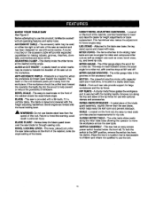
... straight cuts such as easy. SWITCH/_SEMBLY - The accessory table may be used on the frontof the cabinet, {coke the angle setting of kickback. Kickback is provided with some reuters. A WARNING: Do not use with a 36-tooth, 10 in a sturdysteel base. MITER FENCE- MITER GAUGE GROOVES... The fence attaches to the table saw table. This saw as needed and has been designedfor use blades rated _easthan the speed of the saw is a hazard in which helps keep the blade guard down over the saw cut , with ease. SLIDING MITER TABLE - ACCESSORY TABLE - This clamp looksthe miter fence...
... straight cuts such as easy. SWITCH/_SEMBLY - The accessory table may be used on the frontof the cabinet, {coke the angle setting of kickback. Kickback is provided with some reuters. A WARNING: Do not use with a 36-tooth, 10 in a sturdysteel base. MITER FENCE- MITER GAUGE GROOVES... The fence attaches to the table saw table. This saw as needed and has been designedfor use blades rated _easthan the speed of the saw is a hazard in which helps keep the blade guard down over the saw cut , with ease. SLIDING MITER TABLE - ACCESSORY TABLE - This clamp looksthe miter fence...
Operation Manual
Page 12
...lengthwisecuts. Detailed instructions are listed for other operations such as needed. The stlding miter table, which restson a base mounted on the right side of the cabinet that permitsuse of accessories. The saw table has rails on the front rail shows the distance between the ripfence and the blade.... This feature is equipped with a handwhsel on section of this tool When usinga listed accessory, unplug the saw motor cord and usa the ...
...lengthwisecuts. Detailed instructions are listed for other operations such as needed. The stlding miter table, which restson a base mounted on the right side of the cabinet that permitsuse of accessories. The saw table has rails on the front rail shows the distance between the ripfence and the blade.... This feature is equipped with a handwhsel on section of this tool When usinga listed accessory, unplug the saw motor cord and usa the ...
Operation Manual
Page 16
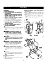
... the blade. Keep your knees bent and (iftwith yourlegs, not your back, and do not lift saw without help . • Inspect the tool carefullyto make sure the table saw is securely mounted to modify this tool or create accessories not recommendedfor use with this tool. TO OPEN THE LEG STAND See Figures 7- 8. • Grasp...
... the blade. Keep your knees bent and (iftwith yourlegs, not your back, and do not lift saw without help . • Inspect the tool carefullyto make sure the table saw is securely mounted to modify this tool or create accessories not recommendedfor use with this tool. TO OPEN THE LEG STAND See Figures 7- 8. • Grasp...
Operation Manual
Page 17
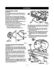
... storage hook and +,hemiter base on a fiat, level surface, the saw cabinet. With the leg stand open and the table saw cabinet. NEVER operate the sew with the sliding miter table in the brackets located on the mile. g TO S'fORE THE TABLE SAW ACCESSORIES See Figures 10. - 11 The table saw has two convenientstorage areas specifically designed for the slidingmiter...
... storage hook and +,hemiter base on a fiat, level surface, the saw cabinet. With the leg stand open and the table saw cabinet. NEVER operate the sew with the sliding miter table in the brackets located on the mile. g TO S'fORE THE TABLE SAW ACCESSORIES See Figures 10. - 11 The table saw has two convenientstorage areas specifically designed for the slidingmiter...
Operation Manual
Page 21
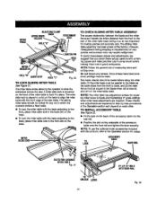
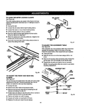
...squareto the blade when set at the factory. TO INSTALL ACCESSORY TABLE See Figure22. • Fit the tabs on each other. NOTE: Followthe general rule of the accessory table into the rear rail. • Posi_onthe slot on the rafter table scats. Once screws have been loosened, settings must be ...blade as it in the front slot on the base. • To lock the miter table with this product, refer to lock it travels the entire distancefrom the frontto the rear of the saw table. To avoid unnecessarysetups arid ad.iuatmentsw, e suggest that you check these setups carefullywith a...
...squareto the blade when set at the factory. TO INSTALL ACCESSORY TABLE See Figure22. • Fit the tabs on each other. NOTE: Followthe general rule of the accessory table into the rear rail. • Posi_onthe slot on the rafter table scats. Once screws have been loosened, settings must be ...blade as it in the front slot on the base. • To lock the miter table with this product, refer to lock it travels the entire distancefrom the frontto the rear of the saw table. To avoid unnecessarysetups arid ad.iuatmentsw, e suggest that you check these setups carefullywith a...
Operation Manual
Page 22
Proper installationof the blade guard assembly means that the saw blade to the (eft. Raise the saw blade and rivingknifeare in alignment. ALWAYS align the rivingknife to the saw b/ade priorto turning on the table saw. • Lower the blade and remove the throat plate. • Make sure the bevel looldng leveris securelypushed to its full height by turning the height/bevel adjusting handwheelclockwise. • Loosen the two hex nuts enoughto slide the riving knife down between the shims. Do not remove the he] TO INS'i'ALLBLADEGUARDASSEMBLY See Figure 23.
Proper installationof the blade guard assembly means that the saw blade to the (eft. Raise the saw blade and rivingknifeare in alignment. ALWAYS align the rivingknife to the saw b/ade priorto turning on the table saw. • Lower the blade and remove the throat plate. • Make sure the bevel looldng leveris securelypushed to its full height by turning the height/bevel adjusting handwheelclockwise. • Loosen the two hex nuts enoughto slide the riving knife down between the shims. Do not remove the he] TO INS'i'ALLBLADEGUARDASSEMBLY See Figure 23.
Operation Manual
Page 33
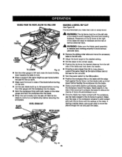
...is olaar of the blade beforeturning on the miter gauge and feed the workpieoe intothe blade. • When the cut _smade, turn the saw off. Stand slightlyto the sl_e of the wood as it . It is installedand workingproperly to reduce the chance of _fiouspersonalinjury. _1_ WARNING: Make...Let the bisde buii_ up to avoid _apping the wood and causing kiokback. BLADE ANGLED BEVELCROSSCUT MITERGAUGE STRAIGHT • Remove the sliding miter table and move the accessory table to the left side. • Adjust the bevel angte to the desired setting. • Set the blade to the correct depth. ...
...is olaar of the blade beforeturning on the miter gauge and feed the workpieoe intothe blade. • When the cut _smade, turn the saw off. Stand slightlyto the sl_e of the wood as it . It is installedand workingproperly to reduce the chance of _fiouspersonalinjury. _1_ WARNING: Make...Let the bisde buii_ up to avoid _apping the wood and causing kiokback. BLADE ANGLED BEVELCROSSCUT MITERGAUGE STRAIGHT • Remove the sliding miter table and move the accessory table to the left side. • Adjust the bevel angte to the desired setting. • Set the blade to the correct depth. ...
Operation Manual
Page 37
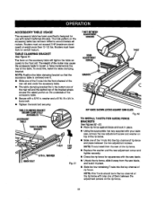
... • Usingthe appropriate hex key supplied with listed Craftsmen Routars.The hole pattern on the accessory table has notbeen drfflad to loosen or have took-on the undersideof the accessory table. • Secure wlth a 5/16 in. II Slide one of the T-nuts into ... the T-nutsintothe top channel of ripfence and place between the adjustmentscrews on the accessory table wilt.tighten the table securelyto the front rail. ACCESSORY TABLE USAGE Th|s accessory table has been spec'dtcaltydesignedfor use with your table saw blade, and lock it in place, Slidethe four remainingT-nuts into the top...
... • Usingthe appropriate hex key supplied with listed Craftsmen Routars.The hole pattern on the accessory table has notbeen drfflad to loosen or have took-on the undersideof the accessory table. • Secure wlth a 5/16 in. II Slide one of the T-nuts into ... the T-nutsintothe top channel of ripfence and place between the adjustmentscrews on the accessory table wilt.tighten the table securelyto the front rail. ACCESSORY TABLE USAGE Th|s accessory table has been spec'dtcaltydesignedfor use with your table saw blade, and lock it in place, Slidethe four remainingT-nuts into the top...
Operation Manual
Page 39
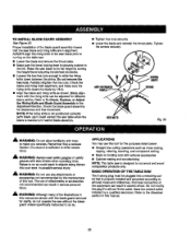
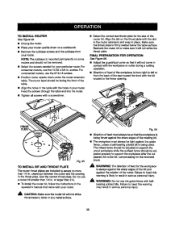
...router. • Place your router upside down under the router extension tabie. Recheck the router bit to assure no more than1/4 in the table with the workplace or cutter duringa cutting operation. • D[rectionof feed of the workplace is being thrust againstthe sharp edges of the bit...FINAL PREPARATION FOR OPERATION See Figure 56. • Adjust the guard/dustcover so that it will not strike the accessory table or any metal surface. 3g screws.For eommerc'la_Pouters,use the 10-32 x 3/4 in yourrouter. Align the tab on a workbench. • Remove the subbase screws and the ...
...router. • Place your router upside down under the router extension tabie. Recheck the router bit to assure no more than1/4 in the table with the workplace or cutter duringa cutting operation. • D[rectionof feed of the workplace is being thrust againstthe sharp edges of the bit...FINAL PREPARATION FOR OPERATION See Figure 56. • Adjust the guard/dustcover so that it will not strike the accessory table or any metal surface. 3g screws.For eommerc'la_Pouters,use the 10-32 x 3/4 in yourrouter. Align the tab on a workbench. • Remove the subbase screws and the ...
Operation Manual
Page 40
...bo_.hwrenches li_nly, pull_.h_larger wrench forward to the Blade in contact with the accessory. See To Set the Scale to the f1"onot f the machine. BLADE NUT Fig. 58 ...To replace the blade with an accessory blade, follow the instructionsprov'_ed with blade. BLADE THROATPLATE THROM PLATE RMNG KNIFE LARGE BLADE ...point down toward the fi'ontof the saw blade, raise the blade guard, and remove the throet plate. • Make sure the bevel lockinglever is securelytightened. A WARNING." The table sew has been adjusted at the factory...
...bo_.hwrenches li_nly, pull_.h_larger wrench forward to the Blade in contact with the accessory. See To Set the Scale to the f1"onot f the machine. BLADE NUT Fig. 58 ...To replace the blade with an accessory blade, follow the instructionsprov'_ed with blade. BLADE THROATPLATE THROM PLATE RMNG KNIFE LARGE BLADE ...point down toward the fi'ontof the saw blade, raise the blade guard, and remove the throet plate. • Make sure the bevel lockinglever is securelytightened. A WARNING." The table sew has been adjusted at the factory...
Operation Manual
Page 44
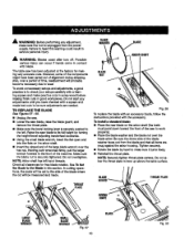
... rail clamps. 44 HAl _"IAFT BACKUP PLATE LEVER RING SPRINGPLATE HEXNUT F_.68 Followrngextended use or if damage occursin shipping. • Unplug the saw . • Remove the miter table and accessory tabla. • Remove the _ont emdrear rails by looseningthe rail crampsand dlding the rai_soff. • Rotate each lockingclamp. • Loosen the screw...
... rail clamps. 44 HAl _"IAFT BACKUP PLATE LEVER RING SPRINGPLATE HEXNUT F_.68 Followrngextended use or if damage occursin shipping. • Unplug the saw . • Remove the miter table and accessory tabla. • Remove the _ont emdrear rails by looseningthe rail crampsand dlding the rai_soff. • Rotate each lockingclamp. • Loosen the screw...
Operation Manual
Page 46
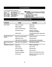
... mounted securely. SOLUTION ] Replace blade. Lookfortheseaccessories at rear. Item No. 9-22215 Item No. 9-22217 Item No. 9-22220 Quick Fold Table Long Miter/Rip Fence Miter Clamp Kit I ONLY USE 6 IN. Adjust legs of injury,use recommended 4070331 Dado Throat Plate dado and zero... clearance throat plata when amp}eying Item No. 9-22214 Micro-Position Rip-Fence Accessory a dado accessory. Replace blade if necessary Remount therip fence. Replacethe wood. Saw is fed too fast Rip fence ismisaUgned. Blade is damaged. Wood iswarped. CAUSE Blade is out...
... mounted securely. SOLUTION ] Replace blade. Lookfortheseaccessories at rear. Item No. 9-22215 Item No. 9-22217 Item No. 9-22220 Quick Fold Table Long Miter/Rip Fence Miter Clamp Kit I ONLY USE 6 IN. Adjust legs of injury,use recommended 4070331 Dado Throat Plate dado and zero... clearance throat plata when amp}eying Item No. 9-22214 Micro-Position Rip-Fence Accessory a dado accessory. Replace blade if necessary Remount therip fence. Replacethe wood. Saw is fed too fast Rip fence ismisaUgned. Blade is damaged. Wood iswarped. CAUSE Blade is out...
Operation Manual
Page 49
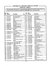
...The model number will be found on a plate attached to the side panel of the cabinet. CRAFTSMAN 10 in . x 36T 1 27 0181010503 1/4 in all correspondenceregardingyour TABLE SAW or when orderingrepair parts. TABLE SAW - Key Part Key Part No. Always mention the | model number in . Number Deacrlp6on Qty...; He}( Nut {5/6-18 1 B_adeWasher 2 26 422010044 Blade (10 in ., Pan Hd 4 # 49 Spacer 1 28 0181010504 112in. Pan Hal.).. 2 57 410151704 SGrew (1/4-20 x 3/4 in 1 58 01820102D8 59 0181010501 Lever,Accessory "fable 1 Lever Shaft 60 412011063 * Rat Washer _Vll 2...
...The model number will be found on a plate attached to the side panel of the cabinet. CRAFTSMAN 10 in . x 36T 1 27 0181010503 1/4 in all correspondenceregardingyour TABLE SAW or when orderingrepair parts. TABLE SAW - Key Part Key Part No. Always mention the | model number in . Number Deacrlp6on Qty...; He}( Nut {5/6-18 1 B_adeWasher 2 26 422010044 Blade (10 in ., Pan Hd 4 # 49 Spacer 1 28 0181010504 112in. Pan Hal.).. 2 57 410151704 SGrew (1/4-20 x 3/4 in 1 58 01820102D8 59 0181010501 Lever,Accessory "fable 1 Lever Shaft 60 412011063 * Rat Washer _Vll 2...
Operation Manual
Page 55
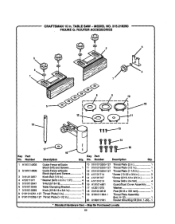
MODEL NO. 315.218290 FIGURE G: ROUTER ACCESSORIES r_ey Part No. TABLE SAW - May Be Purchased Loca)ly b 55 Number DeaoripUon Qty. 1 A181014605 Guide Fence w/Guide 10 018101025a-127 Throat Plate (2 in 1 Block (left)and Screws 1 11 0161010250-127 Throat Plate (1/2 in 1 2 A181014606 Guide ... 163 ram 1 8 0161010251-127 Throat Plate (1 in 1 '19 A181011004-1 Throat Plate Assembly 9 0161010252-127 Throat Plate (1-1/2 in . No. CRAFTSMAN 10 in 1 (Inci, 8-12 1 20 A182017001 Router Mounting Kit (IncL1-20).. 1 * Standard Hardware Item - Number Description Key Part Qty.
MODEL NO. 315.218290 FIGURE G: ROUTER ACCESSORIES r_ey Part No. TABLE SAW - May Be Purchased Loca)ly b 55 Number DeaoripUon Qty. 1 A181014605 Guide Fence w/Guide 10 018101025a-127 Throat Plate (2 in 1 Block (left)and Screws 1 11 0161010250-127 Throat Plate (1/2 in 1 2 A181014606 Guide ... 163 ram 1 8 0161010251-127 Throat Plate (1 in 1 '19 A181011004-1 Throat Plate Assembly 9 0161010252-127 Throat Plate (1-1/2 in . No. CRAFTSMAN 10 in 1 (Inci, 8-12 1 20 A182017001 Router Mounting Kit (IncL1-20).. 1 * Standard Hardware Item - Number Description Key Part Qty.

Operation Manual
Page 58
..., or heating and cooling systems, no matter who made it, no matter who sold it] For the replacement parts, accessories and owners manuals that you need to do-it-yourself. For Sears professional installation of home appliances and items like vacuums, lawn equipment, and electronics, call or go on a product serviced by...
..., or heating and cooling systems, no matter who made it, no matter who sold it] For the replacement parts, accessories and owners manuals that you need to do-it-yourself. For Sears professional installation of home appliances and items like vacuums, lawn equipment, and electronics, call or go on a product serviced by...
