
Technical Guide
Page 3
...chip when combined with a switch-based interconnect demonstrates its side. Hot swappable disks, fans, and power supplies allow repairs to 5.2 Gbytes/sec (peak) using 36.4 GB disks. The rackmount system requires 5U space and can order the system that supports multiple operating ... choose the size of these Alpha chips. Integrated on the World Wide Web: http://www.compaq.com/alphaserver/platforms.html. Compaq AlphaServer DS20E Systems The Compaq AlphaServer DS20E system delivers high performance for one additional 5.25-inch removable media device. The system accommodates...
...chip when combined with a switch-based interconnect demonstrates its side. Hot swappable disks, fans, and power supplies allow repairs to 5.2 Gbytes/sec (peak) using 36.4 GB disks. The rackmount system requires 5U space and can order the system that supports multiple operating ... choose the size of these Alpha chips. Integrated on the World Wide Web: http://www.compaq.com/alphaserver/platforms.html. Compaq AlphaServer DS20E Systems The Compaq AlphaServer DS20E system delivers high performance for one additional 5.25-inch removable media device. The system accommodates...

Technical Guide
Page 10
...to eight AlphaServer systems. Data written to one speeds up to support critical customer configurations. N+1 power redundancy A third power supply can be added to provide redundant power to protect against overheating and possible hardware destruction. The operating systems are monitored to the system...similar to communicate over a common interface, share disks, and spread the computing load across a group of systems that system fans, power supplies, and disks can build high-availability clusters using the PCI to -memory computer system interconnect that permits I /O failures. For ...
...to eight AlphaServer systems. Data written to one speeds up to support critical customer configurations. N+1 power redundancy A third power supply can be added to provide redundant power to protect against overheating and possible hardware destruction. The operating systems are monitored to the system...similar to communicate over a common interface, share disks, and spread the computing load across a group of systems that system fans, power supplies, and disks can build high-availability clusters using the PCI to -memory computer system interconnect that permits I /O failures. For ...

Technical Guide
Page 11
...-day response time. Hardware Warranty The AlphaServer DS20E system and components, including CPU, memory, PCI controllers, and power supplies, have a 3-year on-site, 5-day per week, 9-hour per day hardware warranty with other components. Network products carry the network products warranty. The first year includes on Compaq Services, point your Web browser to http...
...-day response time. Hardware Warranty The AlphaServer DS20E system and components, including CPU, memory, PCI controllers, and power supplies, have a 3-year on-site, 5-day per week, 9-hour per day hardware warranty with other components. Network products carry the network products warranty. The first year includes on Compaq Services, point your Web browser to http...

Technical Guide
Page 13
System Features at a Glance Table 1 provides a quick reference to features of Compaq AlphaServer DS20E systems. Table 1 AlphaServer DS20E Features CPU Features Processor CPU clock speed Cache on chip On-board cache Upgradable in pedestal and cabinet ...GB each) 6 PCI slots (5 PCI and 1 PCI/ISA) Over 500 MB/sec with two 256 MB/sec buses System auto reboot, thermal management, remote system management, RAID 0, 1, 0+1, 5, hot swap of disks, power supplies, and fans, memory failover, ECC memory, ECC cache, N+1 power supply, SMP CPU failover, error logging, optional uninterruptible power supply...
System Features at a Glance Table 1 provides a quick reference to features of Compaq AlphaServer DS20E systems. Table 1 AlphaServer DS20E Features CPU Features Processor CPU clock speed Cache on chip On-board cache Upgradable in pedestal and cabinet ...GB each) 6 PCI slots (5 PCI and 1 PCI/ISA) Over 500 MB/sec with two 256 MB/sec buses System auto reboot, thermal management, remote system management, RAID 0, 1, 0+1, 5, hot swap of disks, power supplies, and fans, memory failover, ECC memory, ECC cache, N+1 power supply, SMP CPU failover, error logging, optional uninterruptible power supply...

Technical Guide
Page 14
...7.5 G, 10+/-3ms 5.0 G, 10+/-3ms Average 5.8 LwA, B 6.3 LwA, B Declared 44 LpAm, dba 49 LpAm, dba Electrical (Power supplies are universal, PFC, auto ranging, 100/240 Vac) Nominal voltage (Vac) Voltage range (Vac) temporary condition Power source phase Nominal frequency (Hz) Frequency range (Hz) RMS current (maximum steady state) Pedestal and rackmount Single...Each power cord 100 90-100 Single 50/60 49-51 / 59-61 6.6 A 780 100 24 A 120 110-128 Single 50/60 49-51 / 59-61 5.5 A 765 120 24 A 200-240 180-250 Single 50/60 49-51 / 59-61 3.0 A 730 220-240 16 A 12 Table 2 AlphaServer DS20E ...
...7.5 G, 10+/-3ms 5.0 G, 10+/-3ms Average 5.8 LwA, B 6.3 LwA, B Declared 44 LpAm, dba 49 LpAm, dba Electrical (Power supplies are universal, PFC, auto ranging, 100/240 Vac) Nominal voltage (Vac) Voltage range (Vac) temporary condition Power source phase Nominal frequency (Hz) Frequency range (Hz) RMS current (maximum steady state) Pedestal and rackmount Single...Each power cord 100 90-100 Single 50/60 49-51 / 59-61 6.6 A 780 100 24 A 120 110-128 Single 50/60 49-51 / 59-61 5.5 A 765 120 24 A 200-240 180-250 Single 50/60 49-51 / 59-61 3.0 A 730 220-240 16 A 12 Table 2 AlphaServer DS20E ...
Reference Guide
Page 3
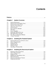
... Overview 1.1 System Enclosures 1-2 1.2 System Parts (Front/Side View 1-4 1.3 System Parts (Rear View 1-6 1.4 Operator Control Panel 1-8 1.5 System Board 1-10 1.6 Server Feature Module 1-12 1.7 PCI Slots 1-14 1.8 Power Supplies 1-16 1.9 Removable Media Storage 1-18 1.10 Hard Disk Drive Storage 1-19 1.11 Two-Way Combination Module 1-20 1.12 Console Terminal 1-21 Chapter 2 Installing the Pedestal...
... Overview 1.1 System Enclosures 1-2 1.2 System Parts (Front/Side View 1-4 1.3 System Parts (Rear View 1-6 1.4 Operator Control Panel 1-8 1.5 System Board 1-10 1.6 Server Feature Module 1-12 1.7 PCI Slots 1-14 1.8 Power Supplies 1-16 1.9 Removable Media Storage 1-18 1.10 Hard Disk Drive Storage 1-19 1.11 Two-Way Combination Module 1-20 1.12 Console Terminal 1-21 Chapter 2 Installing the Pedestal...

Reference Guide
Page 4
... Configuration 5-6 5.4.1 Installing and Removing DIMMs 5-8 5.5 CPU Configuration 5-10 5.6 Installing a PCI or ISA Option 5-11 5.6.1 Installing a PCI Option 5-12 5.6.2 Installing a Multichannel SCSI Option 5-14 5.7 Installing a Redundant Power Supply 5-16 5.8 Network Configuration 5-18 5.9 Disk Drive Configuration 5-20 5.10 Installing Disk Drives 5-22 5.10.1 Drive Status LEDs 5-24 5.11 Configuring the Storage Subsystem 5-26 5.11...
... Configuration 5-6 5.4.1 Installing and Removing DIMMs 5-8 5.5 CPU Configuration 5-10 5.6 Installing a PCI or ISA Option 5-11 5.6.1 Installing a PCI Option 5-12 5.6.2 Installing a Multichannel SCSI Option 5-14 5.7 Installing a Redundant Power Supply 5-16 5.8 Network Configuration 5-18 5.9 Disk Drive Configuration 5-20 5.10 Installing Disk Drives 5-22 5.10.1 Drive Status LEDs 5-24 5.11 Configuring the Storage Subsystem 5-26 5.11...

Reference Guide
Page 9
...3-2 3-3 3-4 3-5 3-6 3-7 3-8 3-9 3-10 3-11 3-12 3-13 3-14 5-1 5-2 DS20E System Variants 1-2 System Parts 1-4 Ports and Connectors 1-6 Control and Status Indicators 1-8 System Board 1-10 Server Feature Module 1-12 PCI Slots (Rack Orientation 1-14 Power Supplies (Pedestal Orientation 1-16 Removable Media Storage 1-18 Four-Slot and Six-Slot Storage Subsystems 1-19 Combination... Module 1-20 Console Terminal Connections 1-21 System Dimensions 2-2 Power Supply Requirements 2-3 Unpacking the Shipment 2-4 Cabling the System 2-5 System Lock and Key ...
...3-2 3-3 3-4 3-5 3-6 3-7 3-8 3-9 3-10 3-11 3-12 3-13 3-14 5-1 5-2 DS20E System Variants 1-2 System Parts 1-4 Ports and Connectors 1-6 Control and Status Indicators 1-8 System Board 1-10 Server Feature Module 1-12 PCI Slots (Rack Orientation 1-14 Power Supplies (Pedestal Orientation 1-16 Removable Media Storage 1-18 Four-Slot and Six-Slot Storage Subsystems 1-19 Combination... Module 1-20 Console Terminal Connections 1-21 System Dimensions 2-2 Power Supply Requirements 2-3 Unpacking the Shipment 2-4 Cabling the System 2-5 System Lock and Key ...

Reference Guide
Page 17
Chapter 1 System Overview This chapter provides an overview of the AlphaServer/AlphaStation DS20E system, including: • System enclosures • System parts (front/side view) • System parts (rear view) • Operator control panel • System board • Server feature module • PCI slots • Power supplies • Removable media storage • Hard disk drive storage • Two-way combination module • Console terminal System Overview 1-1
Chapter 1 System Overview This chapter provides an overview of the AlphaServer/AlphaStation DS20E system, including: • System enclosures • System parts (front/side view) • System parts (rear view) • Operator control panel • System board • Server feature module • PCI slots • Power supplies • Removable media storage • Hard disk drive storage • Two-way combination module • Console terminal System Overview 1-1

Reference Guide
Page 19
... is housed in an enclosure containing the system board, other logic modules, and two power supplies (maximum of brackets, can be mounted in the horizontal position in the vertical position, or with a Power button, Halt button, and Reset button, and diagnostic LEDs System Overview 1-3 The enclosure...ISA or 64-bit PCI slot • A removable media bay that houses six 1.0-inch drives • Two 375-watt power supplies and a bay for a third supply for external options • An operator control panel with the addition of three) with internal fans. An operator control panel includes...
... is housed in an enclosure containing the system board, other logic modules, and two power supplies (maximum of brackets, can be mounted in the horizontal position in the vertical position, or with a Power button, Halt button, and Reset button, and diagnostic LEDs System Overview 1-3 The enclosure...ISA or 64-bit PCI slot • A removable media bay that houses six 1.0-inch drives • Two 375-watt power supplies and a bay for a third supply for external options • An operator control panel with the addition of three) with internal fans. An operator control panel includes...

Reference Guide
Page 28
... panel connector ˜ Main logic board connector ™ Fan 0 connector š Fan 1 connector › Side cover interlock connector œ RMC switch pack (see Chapter 6) 1-12 DS20E Reference Guide The SFM supports the two system fans and three power supplies and monitors the state of the CPU fans on the system board.
... panel connector ˜ Main logic board connector ™ Fan 0 connector š Fan 1 connector › Side cover interlock connector œ RMC switch pack (see Chapter 6) 1-12 DS20E Reference Guide The SFM supports the two system fans and three power supplies and monitors the state of the CPU fans on the system board.

Reference Guide
Page 32
Power supply 0 (PS0) is installed to maintain the proper airflow. 1-16 DS20E Reference Guide A third power supply can be added for redundancy. Figure 1-8 Power Supplies (Pedestal Orientation) CAT0043 NOTE: On a system with two 375-watt power supplies that are connected in a rackmount system. 1.8 Power Supplies The system comes with two power supplies, a power supply blank is the leftmost supply in a pedestal system and the topmost supply in parallel.
Power supply 0 (PS0) is installed to maintain the proper airflow. 1-16 DS20E Reference Guide A third power supply can be added for redundancy. Figure 1-8 Power Supplies (Pedestal Orientation) CAT0043 NOTE: On a system with two 375-watt power supplies that are connected in a rackmount system. 1.8 Power Supplies The system comes with two power supplies, a power supply blank is the leftmost supply in a pedestal system and the topmost supply in parallel.

Reference Guide
Page 33
.... Two internal fans cool the power supply. System Overview 1-17 The power supplies can be removed for the system to operate. The fans are provided: +3.3, +5.0, +12.0, -12.0, +5.0 Aux (+5.0 Aux always powered). The following voltages are temperature controlled and speed up as the power supply temperature increases. N+1 Power Supply Configuration Two power supplies must be installed and working power supplies ever falls below two.
.... Two internal fans cool the power supply. System Overview 1-17 The power supplies can be removed for the system to operate. The fans are provided: +3.3, +5.0, +12.0, -12.0, +5.0 Aux (+5.0 Aux always powered). The following voltages are temperature controlled and speed up as the power supply temperature increases. N+1 Power Supply Configuration Two power supplies must be installed and working power supplies ever falls below two.

Reference Guide
Page 41
Figure 2-2 shows maximum current ratings for a fully loaded system (without monitor or terminal). Figure 2-2 Power Supply Requirements 100-120VAC 7.5A 50/60 Hz 220-240VAC 3.8A 50/60 HZ CAT0013 Installing the Pedestal System 2-3 2.2 Power Requirements The system automatically detects the voltage source when it powers up, and adjusts the power supply input to plug in Chapter 9. Power supply ratings and power cord requirements are given in the AC power connector. It also shows where to accept that voltage.
Figure 2-2 shows maximum current ratings for a fully loaded system (without monitor or terminal). Figure 2-2 Power Supply Requirements 100-120VAC 7.5A 50/60 Hz 220-240VAC 3.8A 50/60 HZ CAT0013 Installing the Pedestal System 2-3 2.2 Power Requirements The system automatically detects the voltage source when it powers up, and adjusts the power supply input to plug in Chapter 9. Power supply ratings and power cord requirements are given in the AC power connector. It also shows where to accept that voltage.

Reference Guide
Page 57
Figure 3-1 Power Requirements and Connections 100-120VAC 7.5A 50/60 Hz 220-240VAC 3.8A 50/60 HZ CAT0012A Installing the Rackmount System 3-3 Power supply ratings and power cord requirements are given in the AC power connector. It also shows where to plug in Chapter 9. 3.2 Power Requirements Figure 3-1 shows maximum current ratings for a fully loaded system (without monitor or terminal).
Figure 3-1 Power Requirements and Connections 100-120VAC 7.5A 50/60 Hz 220-240VAC 3.8A 50/60 HZ CAT0012A Installing the Rackmount System 3-3 Power supply ratings and power cord requirements are given in the AC power connector. It also shows where to plug in Chapter 9. 3.2 Power Requirements Figure 3-1 shows maximum current ratings for a fully loaded system (without monitor or terminal).

Reference Guide
Page 107
...1. Installation Tools You need the following tools to configure and install user-replaceable components, including DIMMs, PCI or ISA options, power supplies, disk drives, and tape drives. WARNING: To prevent injury, access to internal components is limited to persons who have appropriate ... is recommended) • Antistatic wrist strap Configuring and Installing Components 5-1 WARNING: To prevent injury, unplug the power cord before installing components. It also covers configuring CPUs, installing a six-slot storage subsystem, AlphaBIOS configuration utilities, and updating firmware.
...1. Installation Tools You need the following tools to configure and install user-replaceable components, including DIMMs, PCI or ISA options, power supplies, disk drives, and tape drives. WARNING: To prevent injury, access to internal components is limited to persons who have appropriate ... is recommended) • Antistatic wrist strap Configuring and Installing Components 5-1 WARNING: To prevent injury, unplug the power cord before installing components. It also covers configuring CPUs, installing a six-slot storage subsystem, AlphaBIOS configuration utilities, and updating firmware.

Reference Guide
Page 108
... in a three-supply configuration. 5-2 DS20E Reference Guide Shut down the system if you are installing a third power supply for installation or replacement of components, assemble the required equipment, perform shutdown procedures, and attach an antistatic wrist strap. Press the Power button on the ...wrist strap. Remove the side cover (pedestal) or top cover (rackmount). 6. Customer DIMMs CPU upgrades PCI/ISA options Power supply Disk drive cages Service Provider System board System feature module System backplane Fans Combination CD-ROM/floppy disk drive Operator control panel...
... in a three-supply configuration. 5-2 DS20E Reference Guide Shut down the system if you are installing a third power supply for installation or replacement of components, assemble the required equipment, perform shutdown procedures, and attach an antistatic wrist strap. Press the Power button on the ...wrist strap. Remove the side cover (pedestal) or top cover (rackmount). 6. Customer DIMMs CPU upgrades PCI/ISA options Power supply Disk drive cages Service Provider System board System feature module System backplane Fans Combination CD-ROM/floppy disk drive Operator control panel...

Reference Guide
Page 122
5.7 Installing a Redundant Power Supply The system comes with two power supplies. In a three-supply configuration, you can add a third supply for redundancy without shutting down the system. Figure 5-10 Adding a Third Supply (Pedestal Orientation) Power Supply 2 3 Power Power Supply 1 Supply 0 2 1 PK3202 5-16 DS20E Reference Guide You can replace a supply without shutting down the system.
5.7 Installing a Redundant Power Supply The system comes with two power supplies. In a three-supply configuration, you can add a third supply for redundancy without shutting down the system. Figure 5-10 Adding a Third Supply (Pedestal Orientation) Power Supply 2 3 Power Power Supply 1 Supply 0 2 1 PK3202 5-16 DS20E Reference Guide You can replace a supply without shutting down the system.

Reference Guide
Page 123
Loosen the thumbscrew — on the power supply handle, and then pull it from the power supply backplane. 3. Loosen the thumbscrew ˜ on the power supply blank and remove the blank from the system. 4. Power up on the power supply handle, open the handle, and insert the new power supply into the bay. 4. To add a third power supply 1. Loosen the thumbscrew ˜ on the...
Loosen the thumbscrew — on the power supply handle, and then pull it from the power supply backplane. 3. Loosen the thumbscrew ˜ on the power supply blank and remove the blank from the system. 4. Power up on the power supply handle, open the handle, and insert the new power supply into the bay. 4. To add a third power supply 1. Loosen the thumbscrew ˜ on the...

Reference Guide
Page 136
Retain the screws. • Remove the bracket — (previous page) from the new disk drive cage. If replacing a cage: • Remove and discard the bracket from the old drive cage and secure it to the chassis and remove the drive cage. Save the two screws. • Open the power supply door ˜ by loosening the two captive fasteners to gain access to the drive cage. • Remove the four screws securing the old drive cage to the new cage with the two bracket screws. 3 5-30 DS20E Reference Guide PK0977-00 3.
Retain the screws. • Remove the bracket — (previous page) from the new disk drive cage. If replacing a cage: • Remove and discard the bracket from the old drive cage and secure it to the chassis and remove the drive cage. Save the two screws. • Open the power supply door ˜ by loosening the two captive fasteners to gain access to the drive cage. • Remove the four screws securing the old drive cage to the new cage with the two bracket screws. 3 5-30 DS20E Reference Guide PK0977-00 3.

