Service Guide
Page 4
...Compaq ProLiant DL580 Server Maintenance and Service Guide Removal and Replacement Procedures continued Cable Routing Diagrams 2-20 24X or Higher Low-Profile CD-ROM Signal and Power Cables 2-20 Diskette Drive Signal and Power Cables 2-20 Power Switch Cables 2-21 Power Backplane Board Cables 2-22 Peripheral Board Data Cables 2-23 Hot-Plug Power Supply...Utilities Access...3-5 Running the Utilities from the System Partition 3-5 Running the Utilities from Diskette 3-6 Running the Utilities from the Compaq SmartStart and Support Software CD 3-6 Power-On Self-Test 3-7 POST Error Messages 3-7
...Compaq ProLiant DL580 Server Maintenance and Service Guide Removal and Replacement Procedures continued Cable Routing Diagrams 2-20 24X or Higher Low-Profile CD-ROM Signal and Power Cables 2-20 Diskette Drive Signal and Power Cables 2-20 Power Switch Cables 2-21 Power Backplane Board Cables 2-22 Peripheral Board Data Cables 2-23 Hot-Plug Power Supply...Utilities Access...3-5 Running the Utilities from the System Partition 3-5 Running the Utilities from Diskette 3-6 Running the Utilities from the Compaq SmartStart and Support Software CD 3-6 Power-On Self-Test 3-7 POST Error Messages 3-7

Service Guide
Page 6
vi Compaq ProLiant DL580 Server Maintenance and Service Guide Connectors, Switches, and LED Indicators continued LED Indicators ...4-11 Front Bezel LED Indicators 4-12 Interlock Status LED Indicators 4-13 Internal Diagnostics Display Indicator 4-14 Hot-Plug Power Supply LED Indicators 4-15 Hot-Plug Fan LED Indicators... Drive and CD-ROM LED Indicators 4-20 Chapter 5 Physical and Operating Specifications System Unit ...5-2 Hot-Plug Hard Drives 5-3 Hot-Plug Power Supply 5-4 Memory ...5-5 1.44-MB Diskette Drive 5-5 24X Low-Profile CD-ROM Drive 5-6 NC3134 Fast Ethernet NIC 64 PCI Dual Base ...
vi Compaq ProLiant DL580 Server Maintenance and Service Guide Connectors, Switches, and LED Indicators continued LED Indicators ...4-11 Front Bezel LED Indicators 4-12 Interlock Status LED Indicators 4-13 Internal Diagnostics Display Indicator 4-14 Hot-Plug Power Supply LED Indicators 4-15 Hot-Plug Fan LED Indicators... Drive and CD-ROM LED Indicators 4-20 Chapter 5 Physical and Operating Specifications System Unit ...5-2 Hot-Plug Hard Drives 5-3 Hot-Plug Power Supply 5-4 Memory ...5-5 1.44-MB Diskette Drive 5-5 24X Low-Profile CD-ROM Drive 5-6 NC3134 Fast Ethernet NIC 64 PCI Dual Base ...

Service Guide
Page 8
...at a time. All troubleshooting and repair procedures are extended to the equipment: If the system has multiple power supplies, disconnect power from the power supplies. Plug the power cord into a properly grounded AC outlet only. CAUTION: The computer is a single-rack installation. Improper ...the complexity of the rack rests on the leveling jacks. Do not disable the power cord grounding plug. viii Compaq ProLiant DL580 Server Maintenance and Service Guide Compaq Technician Notes WARNING: Only authorized technicians trained by unplugging all times. The stabilizing ...
...at a time. All troubleshooting and repair procedures are extended to the equipment: If the system has multiple power supplies, disconnect power from the power supplies. Plug the power cord into a properly grounded AC outlet only. CAUTION: The computer is a single-rack installation. Improper ...the complexity of the rack rests on the leveling jacks. Do not disable the power cord grounding plug. viii Compaq ProLiant DL580 Server Maintenance and Service Guide Compaq Technician Notes WARNING: Only authorized technicians trained by unplugging all times. The stabilizing ...

Service Guide
Page 12
...-ROM stop c) Peripheral board card guide * d) PCI card guide retainer * e) Filter cover * f) Memory board guide * g) Optional hot-plug expansion board retainer * h) Optional expansion board retainer * 5 Power supply blank cover 6 Hard drive blank cover * Not shown Illustrated Parts Catalog 1-3 Spare Part Number 177899-001 177900-001 191444-001 187681-001 122641-001 122759...
...-ROM stop c) Peripheral board card guide * d) PCI card guide retainer * e) Filter cover * f) Memory board guide * g) Optional hot-plug expansion board retainer * h) Optional expansion board retainer * 5 Power supply blank cover 6 Hard drive blank cover * Not shown Illustrated Parts Catalog 1-3 Spare Part Number 177899-001 177900-001 191444-001 187681-001 122641-001 122759...

Service Guide
Page 14
...1 ½ inch) 8 Hot-plug fan assembly, 92 x 25.4 mm (3.62 x 1 inch) 9 Hot-plug fan assembly, 80 x 20 mm (3.15 x 0.79 inch) System Components 10 Power supply, 450 watts, hot-plug 11 Replacement battery, peripheral board 12 Processors a) 700-MHz (1-MB) processor with green heatsink b) 700-MHz (2-MB) processor with green heatsink..., CL-2) * 18 512-MB DIMM (100-MHz SDRAM, 128-Megabit, CL-2) * 19 512-MB DIMM (100-MHz SDRAM, 256-Megabit, CL-2) * 20 1-GB DIMM (100-MHz SDRAM, 256-Megabit, CL-2) * * Not shown Spare Part Number 177902-001 177903-001 177901-001 101920-001 179322-001 175292-001 175293...
...1 ½ inch) 8 Hot-plug fan assembly, 92 x 25.4 mm (3.62 x 1 inch) 9 Hot-plug fan assembly, 80 x 20 mm (3.15 x 0.79 inch) System Components 10 Power supply, 450 watts, hot-plug 11 Replacement battery, peripheral board 12 Processors a) 700-MHz (1-MB) processor with green heatsink b) 700-MHz (2-MB) processor with green heatsink..., CL-2) * 18 512-MB DIMM (100-MHz SDRAM, 128-Megabit, CL-2) * 19 512-MB DIMM (100-MHz SDRAM, 256-Megabit, CL-2) * 20 1-GB DIMM (100-MHz SDRAM, 256-Megabit, CL-2) * * Not shown Spare Part Number 177902-001 177903-001 177901-001 101920-001 179322-001 175292-001 175293...

Service Guide
Page 19
...qualified personnel. WARNING: To reduce the risk of injury from electric shock hazards, do not open this surface is supplied by multiple sources of power. Weight kg Weight lb This symbol indicates that the component exceeds the recommended weight for injury exists if warnings are ...documentation for manual material handling. This symbol indicates the presence of electric shock, fire, or damage to handle safely. This symbol on power supplies or systems indicate the equipment is contacted, the potential for any of the following symbols indicates the presence of a potential hazard. ...
...qualified personnel. WARNING: To reduce the risk of injury from electric shock hazards, do not open this surface is supplied by multiple sources of power. Weight kg Weight lb This symbol indicates that the component exceeds the recommended weight for injury exists if warnings are ...documentation for manual material handling. This symbol indicates the presence of electric shock, fire, or damage to handle safely. This symbol on power supplies or systems indicate the equipment is contacted, the potential for any of the following symbols indicates the presence of a potential hazard. ...

Service Guide
Page 20
... and the drives, but portions of the server. Non-hot-pluggable parts include the processors, some expansion boards, fans, and power supplies. 2-4 Compaq ProLiant DL580 Server Maintenance and Service Guide Preparation Procedures The system power in the ProLiant DL580 server does not completely power down with products capable of options other than on and standby, rather than hot-plug...
... and the drives, but portions of the server. Non-hot-pluggable parts include the processors, some expansion boards, fans, and power supplies. 2-4 Compaq ProLiant DL580 Server Maintenance and Service Guide Preparation Procedures The system power in the ProLiant DL580 server does not completely power down with products capable of options other than on and standby, rather than hot-plug...

Service Guide
Page 21
... see "Electrostatic Discharge Information" earlier in this chapter. Press the Power On/Standby switch. NOTE: It is amber and that disables the main power supply output and provides only auxiliary power (+5V) to the equipment, observe local occupational health and safety ...injury from the system. 4. Refer to completely disconnect power from electric shock, remove all power cords to the Compaq ProLiant DL580 Server Setup and Installation Guide for non-hot-plug devices: 1. Removal and Replacement Procedures 2-5 Powering Down the Server Before beginning any of the removal...
... see "Electrostatic Discharge Information" earlier in this chapter. Press the Power On/Standby switch. NOTE: It is amber and that disables the main power supply output and provides only auxiliary power (+5V) to the equipment, observe local occupational health and safety ...injury from the system. 4. Refer to completely disconnect power from electric shock, remove all power cords to the Compaq ProLiant DL580 Server Setup and Installation Guide for non-hot-plug devices: 1. Removal and Replacement Procedures 2-5 Powering Down the Server Before beginning any of the removal...
Service Guide
Page 22
2-6 Compaq ProLiant DL580 Server Maintenance and Service Guide Rack Warnings WARNING: To reduce the risk of the rack as it rolls down the ramp from the pallet; The ... moving the rack. Do not attempt to the floor. Remove all cautions and warnings throughout the installation instructions provided with the server. Heed all pluggable power supplies and modules to the equipment: Observe local occupational safety requirements and guidelines for any reason. Be sure that precautions have been taken to provide for...
2-6 Compaq ProLiant DL580 Server Maintenance and Service Guide Rack Warnings WARNING: To reduce the risk of the rack as it rolls down the ramp from the pallet; The ... moving the rack. Do not attempt to the floor. Remove all cautions and warnings throughout the installation instructions provided with the server. Heed all pluggable power supplies and modules to the equipment: Observe local occupational safety requirements and guidelines for any reason. Be sure that precautions have been taken to provide for...

Service Guide
Page 23
...operation during normal operation. -OrInstall the server in the product documentation. Power down the product and disconnect all AC power cords before removing covers and touching internal components. CAUTION: The ProLiant DL580 server must always be performed by individuals who are detailed to hazardous ... complexity of electric shock or damage to the equipment: Allow the product to the server. Not overloading AC power to the rack power supply circuit reduces the risk of repair specified in the procedures in a controlled access location where only qualified personnel have...
...operation during normal operation. -OrInstall the server in the product documentation. Power down the product and disconnect all AC power cords before removing covers and touching internal components. CAUTION: The ProLiant DL580 server must always be performed by individuals who are detailed to hazardous ... complexity of electric shock or damage to the equipment: Allow the product to the server. Not overloading AC power to the rack power supply circuit reduces the risk of repair specified in the procedures in a controlled access location where only qualified personnel have...
Service Guide
Page 40
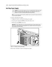
... 2-17. Unplug the AC power cord from the server. Removing a hot-plug power supply Reverse steps 1 through 3 to place the system in the up the release lever. 3. Do not operate for a hot-plug power supply replacement in a power supply configuration. 2-24 Compaq ProLiant DL580 Server Maintenance and Service Guide Hot-Plug Power Supply CAUTION: If one of the power supplies is removed exactly the...
... 2-17. Unplug the AC power cord from the server. Removing a hot-plug power supply Reverse steps 1 through 3 to place the system in the up the release lever. 3. Do not operate for a hot-plug power supply replacement in a power supply configuration. 2-24 Compaq ProLiant DL580 Server Maintenance and Service Guide Hot-Plug Power Supply CAUTION: If one of the power supplies is removed exactly the...

Service Guide
Page 44
2-28 Compaq ProLiant DL580 Server Maintenance and Service Guide Peripheral Board CAUTION: Disconnect all power cords from the power supplies to break. 6. Disconnect all power cords from the system. CAUTION: Rotating the peripheral board handles a full 90 degrees causes the handles to completely remove power from the server before removing the peripheral board. See "Preparation Procedures" earlier in this...
2-28 Compaq ProLiant DL580 Server Maintenance and Service Guide Peripheral Board CAUTION: Disconnect all power cords from the power supplies to break. 6. Disconnect all power cords from the system. CAUTION: Rotating the peripheral board handles a full 90 degrees causes the handles to completely remove power from the server before removing the peripheral board. See "Preparation Procedures" earlier in this...

Service Guide
Page 49
...this chapter. 8. Remove the peripheral board. See "Hot-Plug Power Supply" earlier in this chapter. 5. Loosen the two captive thumbscrews that secure the center wall to replace the center wall. Lift the center wall up from the power backplane board. 6. Removing the center wall Reverse steps 1 through... removable media assembly. Remove the PCI guide bracket. Remove the three fan assemblies secured to the center wall. Pull the center hot-plug power supply out of the chassis. See "Top Access Panel" earlier in this chapter. 4. See "Hot-Plug Fan Assembly Identification" and "Hot-...
...this chapter. 8. Remove the peripheral board. See "Hot-Plug Power Supply" earlier in this chapter. 5. Loosen the two captive thumbscrews that secure the center wall to replace the center wall. Lift the center wall up from the power backplane board. 6. Removing the center wall Reverse steps 1 through... removable media assembly. Remove the PCI guide bracket. Remove the three fan assemblies secured to the center wall. Pull the center hot-plug power supply out of the chassis. See "Top Access Panel" earlier in this chapter. 4. See "Hot-Plug Fan Assembly Identification" and "Hot-...

Service Guide
Page 60
... the four T-15 screws that secure the backplane board to replace the power backplane board assembly. 2-44 Compaq ProLiant DL580 Server Maintenance and Service Guide Power Backplane Board To remove the power backplane board: 1. See "PCI Guide Bracket" earlier in this chapter. 4. Disconnect all power supplies partially out of the unit. See "Preparation Procedures" earlier in this chapter...
... the four T-15 screws that secure the backplane board to replace the power backplane board assembly. 2-44 Compaq ProLiant DL580 Server Maintenance and Service Guide Power Backplane Board To remove the power backplane board: 1. See "PCI Guide Bracket" earlier in this chapter. 4. Disconnect all power supplies partially out of the unit. See "Preparation Procedures" earlier in this chapter...

Service Guide
Page 63
... assemblies. Remove the PCI guide bracket. See "System Board with Subpan" earlier in this chapter. Remove all hot-plug power supplies. Remove the primary power supply cable and the secondary power supply cable from the two rear power outlets. See "Center Wall" earlier in this chapter. 7. See "PCI Guide Bracket" earlier in this chapter. 6. Cut the plastic...
... assemblies. Remove the PCI guide bracket. See "System Board with Subpan" earlier in this chapter. Remove all hot-plug power supplies. Remove the primary power supply cable and the secondary power supply cable from the two rear power outlets. See "Center Wall" earlier in this chapter. 7. See "PCI Guide Bracket" earlier in this chapter. 6. Cut the plastic...

Service Guide
Page 65
Removing the AC power cable assembly from the chassis 12. Removal and Replacement Procedures 2-49 11. Remove the two T-15 screws securing the plug assembly connector to replace the AC power cord and plug assembly. Pull the AC power cord and plug assembly back, then out of the chassis. 8 Figure 2-42. Removing the AC power supply connector from the chassis Reverse steps 1 through 12 to the chassis, then push in the plug assembly . 6 7 Figure 2-41.
Removing the AC power cable assembly from the chassis 12. Removal and Replacement Procedures 2-49 11. Remove the two T-15 screws securing the plug assembly connector to replace the AC power cord and plug assembly. Pull the AC power cord and plug assembly back, then out of the chassis. 8 Figure 2-42. Removing the AC power supply connector from the chassis Reverse steps 1 through 12 to the chassis, then push in the plug assembly . 6 7 Figure 2-41.

Service Guide
Page 76
... step, and then run Diagnostics or the System Configuration Utility. Diagnostics and Troubleshooting 3-7 Power-On Self-Test Power-On Self-Test (POST) is a series of the actions listed require you to ...NOTE: Many of diagnostic tests that the computer system is functioning properly: System ROM Keyboard Power supply System board Memory Memory expansion boards Controllers Diskette drives Hard drives Fans POST Error Messages ...If POST finds an error in the system, an error condition is powered up. After completing each step, run on the screen during POST or after resetting ...
... step, and then run Diagnostics or the System Configuration Utility. Diagnostics and Troubleshooting 3-7 Power-On Self-Test Power-On Self-Test (POST) is a series of the actions listed require you to ...NOTE: Many of diagnostic tests that the computer system is functioning properly: System ROM Keyboard Power supply System board Memory Memory expansion boards Controllers Diskette drives Hard drives Fans POST Error Messages ...If POST finds an error in the system, an error condition is powered up. After completing each step, run on the screen during POST or after resetting ...

Service Guide
Page 80
...X) failure detected 2 short 1612-Primary power 2 short supply failure 1613-Low System None Battery 1615-Power Supply None Failure, Power Supply Unplugged, or Power Supply Fan Failure in system environment. Primary power supply has failed. A power supply has failed. Replace or check specified power supply. Check and replace failed controller assembly... 2 short 1611-Fan failure detected 2 short 1611-I /O fan failed CPU fan failed Check fans. Replace power supply as soon as possible. Run Diagnostics. Check and replace missing or failed assembly. Verify SCSI bus cabling. Replace...
...X) failure detected 2 short 1612-Primary power 2 short supply failure 1613-Low System None Battery 1615-Power Supply None Failure, Power Supply Unplugged, or Power Supply Fan Failure in system environment. Primary power supply has failed. A power supply has failed. Replace or check specified power supply. Check and replace failed controller assembly... 2 short 1611-Fan failure detected 2 short 1611-I /O fan failed CPU fan failed Check fans. Replace power supply as soon as possible. Run Diagnostics. Check and replace missing or failed assembly. Verify SCSI bus cabling. Replace...

Service Guide
Page 114
... be reattached to your user documentation for cable guidelines and reconfigure as indicated. Replace the power supply. SOLUTION: Replace the power supply. Refer to an available bus. A power supply in the external storage unit has failed. Storage enclosure on SCSI bus X indicated a power supply failure. The side panel of the storage unit is open. continued The current cable...
... be reattached to your user documentation for cable guidelines and reconfigure as indicated. Replace the power supply. SOLUTION: Replace the power supply. Refer to an available bus. A power supply in the external storage unit has failed. Storage enclosure on SCSI bus X indicated a power supply failure. The side panel of the storage unit is open. continued The current cable...
Service Guide
Page 125
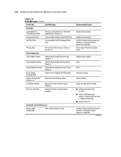
... Compaq ProLiant DL580 Server Maintenance and Service Guide Table 3-19 Event Messages continued Event Type Event Message Processor Correctable Error Threshold exceeded Processor Correctable Error Threshold passed (Slot X, Socket X) Uncorrectable Error Unrecoverable Host Bus Data Parity Error Host Bus Error Unrecoverable Host Bus Address Parity Error PCI Bus Error Power Subsystem Power Supply Failure Power Supply Inserted Power Supply Removed Power Supply...
... Compaq ProLiant DL580 Server Maintenance and Service Guide Table 3-19 Event Messages continued Event Type Event Message Processor Correctable Error Threshold exceeded Processor Correctable Error Threshold passed (Slot X, Socket X) Uncorrectable Error Unrecoverable Host Bus Data Parity Error Host Bus Error Unrecoverable Host Bus Address Parity Error PCI Bus Error Power Subsystem Power Supply Failure Power Supply Inserted Power Supply Removed Power Supply...

