Operation Manual
Page 1
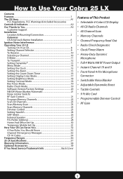
... Cobra 25 LX Contents Features ...1 The CB Story A1 FCC Regulations, FCC Warnings & Included Accessories Controls & Indicators A2 Our Thanks to You A3 Customer Support Installation Location & Mounting/Connection 2 Antennas CB Antenna & Marine Installation 6 Ignition Noise Interference 7 Operating Your 25 LX Turning On Your CB 8 Setting Channel Selector 9 To Receive 10 Selecting a Channel 10 S-Meter...11 To Transmit 12 Setting Dynamike 13 Menu Mode 14 Setting the Clock 15 Setting...
... Cobra 25 LX Contents Features ...1 The CB Story A1 FCC Regulations, FCC Warnings & Included Accessories Controls & Indicators A2 Our Thanks to You A3 Customer Support Installation Location & Mounting/Connection 2 Antennas CB Antenna & Marine Installation 6 Ignition Noise Interference 7 Operating Your 25 LX Turning On Your CB 8 Setting Channel Selector 9 To Receive 10 Selecting a Channel 10 S-Meter...11 To Transmit 12 Setting Dynamike 13 Menu Mode 14 Setting the Clock 15 Setting...

Operation Manual
Page 2
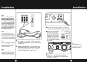
..., yet does not interfere with the mounting bracket in the universal mounting bracket by two thumbscrews which allow for the mounting screws. The bracket includes two selftapping screws and star washers. The mounting must be mechanically strong, conveniently located. 3 Connect the antenna cable plug to mark the location for adjustment at a convenient angle. Installation Installation Location Location Plan location of the...
..., yet does not interfere with the mounting bracket in the universal mounting bracket by two thumbscrews which allow for the mounting screws. The bracket includes two selftapping screws and star washers. The mounting must be mechanically strong, conveniently located. 3 Connect the antenna cable plug to mark the location for adjustment at a convenient angle. Installation Installation Location Location Plan location of the...
Operation Manual
Page 3
... connected to a constant 12V source to red lead of unit and install unit in bracket securely. 5 Turns itself on front of the DC power cord to an accessory 12 volt fuse. Note 4 In a negative grounded vehicle, connect the The radio should be placed under the dash so microphone is readily accesCHs9i/b19le. 1 2 3 4 TX PWR TX CB / PA RX...
... connected to a constant 12V source to red lead of unit and install unit in bracket securely. 5 Turns itself on front of the DC power cord to an accessory 12 volt fuse. Note 4 In a negative grounded vehicle, connect the The radio should be placed under the dash so microphone is readily accesCHs9i/b19le. 1 2 3 4 TX PWR TX CB / PA RX...

Operation Manual
Page 4
...), using a single antenna. Note 3-way Combination Antennas are also available which allow maxi- For models with the vehicle's engine turned off. Note Because many newer trucks feature fiberglass door skins, the outside mirror must be high enough to make good communications impossible. Before attempting installation , consult your Cobra dealer or a 2-way radio technician for information regarding an adequate...
...), using a single antenna. Note 3-way Combination Antennas are also available which allow maxi- For models with the vehicle's engine turned off. Note Because many newer trucks feature fiberglass door skins, the outside mirror must be high enough to make good communications impossible. Before attempting installation , consult your Cobra dealer or a 2-way radio technician for information regarding an adequate...
Operation Manual
Page 5
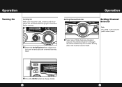
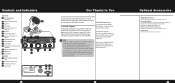
Operation Operation Turning On CH 9 / 19 Turning On CB / PA Make sure the power cord, antenna and microNB phone are connected to their proper connectors CH9 /b19efore startin1 g. 2 3 4 TX PWR TX CB / PA RX 1 2 3 4 TX PWR TX Setting ChannelRSXelector SIG 1 3 5 7 9 +30dB VOL SCAN / M SCAN MENU PU SH ENTER SQ DIM ... MAX MIN OFF MIN 1 Rotate the On/Off Volume knob clockwise to turn unit on and adjust to select CB or PA (public address) mode. The selected channel (1 through 40) will be indicated by the readout directly above the channel selector knob CH 9 / 19 CB / PA 1 2 3 4 ...
Operation Operation Turning On CH 9 / 19 Turning On CB / PA Make sure the power cord, antenna and microNB phone are connected to their proper connectors CH9 /b19efore startin1 g. 2 3 4 TX PWR TX CB / PA RX 1 2 3 4 TX PWR TX Setting ChannelRSXelector SIG 1 3 5 7 9 +30dB VOL SCAN / M SCAN MENU PU SH ENTER SQ DIM ... MAX MIN OFF MIN 1 Rotate the On/Off Volume knob clockwise to turn unit on and adjust to select CB or PA (public address) mode. The selected channel (1 through 40) will be indicated by the readout directly above the channel selector knob CH 9 / 19 CB / PA 1 2 3 4 ...
Operation Manual
Page 7
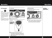
...radio before transmitting. 1 Select desired channel. Setting Dynamike® 2 Push and hold the microphone two inches from your mouth and speak in some conditions. Release to transmit. Prolonged transmitting without an antenna, or a poorly matched antenna, could cause damage to be reduced in a clear, normal voice. When transmitting, hold mic... / M SCAN Setting Dynamike® 1 2 3 4 TX PWR MEM NB TX RX ThDisIMc/oESnCtrols the microphone sensitivity SCAN / M SCAN (outgoing audio level). Rules and Regulations included with this unit before transmitting. Operation Operation To...
...radio before transmitting. 1 Select desired channel. Setting Dynamike® 2 Push and hold the microphone two inches from your mouth and speak in some conditions. Release to transmit. Prolonged transmitting without an antenna, or a poorly matched antenna, could cause damage to be reduced in a clear, normal voice. When transmitting, hold mic... / M SCAN Setting Dynamike® 1 2 3 4 TX PWR MEM NB TX RX ThDisIMc/oESnCtrols the microphone sensitivity SCAN / M SCAN (outgoing audio level). Rules and Regulations included with this unit before transmitting. Operation Operation To...
Operation Manual
Page 8
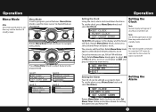
...SWR /CAL S/RF RF SWR CAL OFF SIG 1 3 RADIO CHECK RX S/RF S/RF SWR SETTING 5 7 9 +30dB M SE NWURP/CUASLH CAL ENTER RF MSEIGM 1 MWIXN!3 RX MEM SCAN 5 7 9 +M30AdXB CB / WX / PA MIN MENU PU SH ENTER VOL SQ DYNAMIKE VOL SQ RDFYGNAAINMIKE DELTA TUNE T BACK CH 9/ EX19IT DIM ESC MEM WX ! Follow instructions above for setting...4: DYNAMIKE Your 25 LX can be utilized as an alarm clock. Clock knob is turned off. To set . CB / PA RX ALARM CLOCK DIM / ESNCote OFF NB SIG 1 3 MIN 5 7 M9AX+3M0INdB 1 2 3 4 TX PWR TX Rotate Menu/EntReXr menu levels. SET CLOCK Note SCAN ...
...SWR /CAL S/RF RF SWR CAL OFF SIG 1 3 RADIO CHECK RX S/RF S/RF SWR SETTING 5 7 9 +30dB M SE NWURP/CUASLH CAL ENTER RF MSEIGM 1 MWIXN!3 RX MEM SCAN 5 7 9 +M30AdXB CB / WX / PA MIN MENU PU SH ENTER VOL SQ DYNAMIKE VOL SQ RDFYGNAAINMIKE DELTA TUNE T BACK CH 9/ EX19IT DIM ESC MEM WX ! Follow instructions above for setting...4: DYNAMIKE Your 25 LX can be utilized as an alarm clock. Clock knob is turned off. To set . CB / PA RX ALARM CLOCK DIM / ESNCote OFF NB SIG 1 3 MIN 5 7 M9AX+3M0INdB 1 2 3 4 TX PWR TX Rotate Menu/EntReXr menu levels. SET CLOCK Note SCAN ...

Operation Manual
Page 9
.../ PA DIM SIG N1ote 3 5 7 9 +30dB Press Dim/Escape buttMoEnN UtoPU retuDrnYNtoAMCBIKsEtandby mode. OFF MIN MAX MIN OFF Follow instructions in (from green to blue to amber to red then back to set alarm duration Display Color. SH ESC EEnN TtEeRr MEM WX ! CH 9 / 19 RX 1 3 5 79 CB / PA...ENTER VOL SQ NB RF GAIN Setting Display Color Mode DYNAMIKE Default snooze time lRenXgth F is set in Setting the Clock section MIN MAX MIN (page 17) to set MEM the NB color. Setting the Count Down Timer Note Length. CH 9 / 19 4 1 2 3 4 TX PWR TX TURN CH KNOB TO SCAN / M...
.../ PA DIM SIG N1ote 3 5 7 9 +30dB Press Dim/Escape buttMoEnN UtoPU retuDrnYNtoAMCBIKsEtandby mode. OFF MIN MAX MIN OFF Follow instructions in (from green to blue to amber to red then back to set alarm duration Display Color. SH ESC EEnN TtEeRr MEM WX ! CH 9 / 19 RX 1 3 5 79 CB / PA...ENTER VOL SQ NB RF GAIN Setting Display Color Mode DYNAMIKE Default snooze time lRenXgth F is set in Setting the Clock section MIN MAX MIN (page 17) to set MEM the NB color. Setting the Count Down Timer Note Length. CH 9 / 19 4 1 2 3 4 TX PWR TX TURN CH KNOB TO SCAN / M...

Operation Manual
Page 10
... set the Night-Dim level, repeat instructions above then select Night-Dim. Turn Menu/Enter clockwise to increase brightness and turn ... Operation Setting Brightness Mode Note If an attempt is made to exceed the highest or lowest contrast levels, 1 error beep ...set the day bright level, turn counter-clockwise to main menu. Press Menu/Enter knob to advance to next test. 1 Radio Check Mode Note Press Dim/Escape button to return to select Day-Bright. VOCLBR/XPASQ 2 POWER MEM R1FMENP2U O3PWU4SEHTRXEPNWTOERRUTTPX UT PASS RX OUTPUT NB 3 SCAN / M SCAN RF POWER OUTPUT...
... set the Night-Dim level, repeat instructions above then select Night-Dim. Turn Menu/Enter clockwise to increase brightness and turn ... Operation Setting Brightness Mode Note If an attempt is made to exceed the highest or lowest contrast levels, 1 error beep ...set the day bright level, turn counter-clockwise to main menu. Press Menu/Enter knob to advance to next test. 1 Radio Check Mode Note Press Dim/Escape button to return to select Day-Bright. VOCLBR/XPASQ 2 POWER MEM R1FMENP2U O3PWU4SEHTRXEPNWTOERRUTTPX UT PASS RX OUTPUT NB 3 SCAN / M SCAN RF POWER OUTPUT...

Operation Manual
Page 11
.... In weak signal areas turn clockwise to original factory settings. Operation Operation Software Version/Factory Settings Note Default display color is used to OFF mode all noise filtration will be turned off. Software Version/Factory Settings Displays current software version and returns unit to increase gain. 20 21 CONTRAST RADIO CHECK SETTING SOFTWARE VER GO TO DEFAULT...
.... In weak signal areas turn clockwise to original factory settings. Operation Operation Software Version/Factory Settings Note Default display color is used to OFF mode all noise filtration will be turned off. Software Version/Factory Settings Displays current software version and returns unit to increase gain. 20 21 CONTRAST RADIO CHECK SETTING SOFTWARE VER GO TO DEFAULT...

Operation Manual
Page 12
... and hold Scan/MemScan button. Note Keying the microphone will appear. Operation Operation Program Memory Channels Note The radio should be squelched before scan features are 1 3att5em7 p9t+e3d0tdoB be programmed, 3 error beeps will bMeENhUeaPUrdSHaEnNdTER VO"LMemSoQry Full" will be ... MDAYXNAMMIKINE 1 Press Dim/Esc button to CB mode. Program Memory Channels Set first channel. See sMeINtting insMtrAuXctiMoInN s on page 20. return to toggle between day and night settings. Press and hold the MEM itchoenstcuarnnMsbEuoNUtfft.oPUnSuHnEtNilTER VOL SQ MEM NB ...
... and hold Scan/MemScan button. Note Keying the microphone will appear. Operation Operation Program Memory Channels Note The radio should be squelched before scan features are 1 3att5em7 p9t+e3d0tdoB be programmed, 3 error beeps will bMeENhUeaPUrdSHaEnNdTER VO"LMemSoQry Full" will be ... MDAYXNAMMIKINE 1 Press Dim/Esc button to CB mode. Program Memory Channels Set first channel. See sMeINtting insMtrAuXctiMoInN s on page 20. return to toggle between day and night settings. Press and hold the MEM itchoenstcuarnnMsbEuoNUtfft.oPUnSuHnEtNilTER VOL SQ MEM NB ...
Operation Manual
Page 13
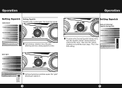
...24 25 Now turn the Squelch control counterclockwise until the noise stops. MEM MENU PU SH ENTER VOL SQ MEDIUM SIGNALS 1 2 3 4 TX PWR TX SCARNX/ M SCAN Operation SIG 1 NB 3 5 7 9 +30dB MEM NB DIM / ESC MENU PUSH SENeTEtRting Squelch VOL SQ RF GAIN Gate set to Desired Squelch Setting (...opens the "gate" allowing all signals in. Operation CH 9 / 19 CH 9 / 19 1 2 3 4 TX PWR TX CB / PA Setting SquelCcBh/ PA Setting Squelch RX NB Gate closed STRONG SIGNALS NB SquelchSIiGs th1 e "co3ntro5l 7ga9te+"3f0odrBincoming signals. CB / PA RX MIN MAX MIN 3 To achieve the ...
...24 25 Now turn the Squelch control counterclockwise until the noise stops. MEM MENU PU SH ENTER VOL SQ MEDIUM SIGNALS 1 2 3 4 TX PWR TX SCARNX/ M SCAN Operation SIG 1 NB 3 5 7 9 +30dB MEM NB DIM / ESC MENU PUSH SENeTEtRting Squelch VOL SQ RF GAIN Gate set to Desired Squelch Setting (...opens the "gate" allowing all signals in. Operation CH 9 / 19 CH 9 / 19 1 2 3 4 TX PWR TX CB / PA Setting SquelCcBh/ PA Setting Squelch RX NB Gate closed STRONG SIGNALS NB SquelchSIiGs th1 e "co3ntro5l 7ga9te+"3f0odrBincoming signals. CB / PA RX MIN MAX MIN 3 To achieve the ...

Operation Manual
Page 14
... Note 1 2 3 4 TX PWR TX RX SCANT/hMe eSxCteArNnal speaker should have 8-ohm impedance and be rated to the RF output (outgoing signal) and incoming receive signal. Operation Operation S/RF Meter S/RF Meter This meter swings proportionately to handle at 10 watts. are OFF MIN MAX MIN 26 27 MEM NB nected. MENU PU SH...
... Note 1 2 3 4 TX PWR TX RX SCANT/hMe eSxCteArNnal speaker should have 8-ohm impedance and be rated to the RF output (outgoing signal) and incoming receive signal. Operation Operation S/RF Meter S/RF Meter This meter swings proportionately to handle at 10 watts. are OFF MIN MAX MIN 26 27 MEM NB nected. MENU PU SH...

Operation Manual
Page 16
Note For further information call Cobra Customer Service 1.773.889.3087. This adapter and a magnetic mount antenna allow you to purchase an optional cigarette lighter adapter from home or office you may want to quickly "install" your COBRA dealer. Temporary Mobile Set-Up 2 Plug power cable into back of the power pack. 30 31 Temporary Mobile Operation For temporary mobile operation...
Note For further information call Cobra Customer Service 1.773.889.3087. This adapter and a magnetic mount antenna allow you to purchase an optional cigarette lighter adapter from home or office you may want to quickly "install" your COBRA dealer. Temporary Mobile Set-Up 2 Plug power cable into back of the power pack. 30 31 Temporary Mobile Operation For temporary mobile operation...

Operation Manual
Page 17
... the channel. Profanity is prohibited. 1. CB Distress Data When transmitting an emergency, you alert while traveling A Few Rules You Should Know A. Be exact. Give details and help in event of permitted and prohibited messages for emergencies Be sure antenna is required to let others off the air by reporting erratic drivers • Get "local information...
... the channel. Profanity is prohibited. 1. CB Distress Data When transmitting an emergency, you alert while traveling A Few Rules You Should Know A. Be exact. Give details and help in event of permitted and prohibited messages for emergencies Be sure antenna is required to let others off the air by reporting erratic drivers • Get "local information...
Operation Manual
Page 18
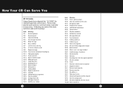
... up at Urgent business Anything for us? Return to mic 10-93 Check my frequency on this channel 10-94 Give me a long count 10-99 Mission...Turn to channel 10-42 Traffic accident at 10-43 Traffic tie up for contact 10-30 Does not conform to FCC rules 10-33 Emergency traffic 10-34 Trouble at this station 10-35 Confidential information...25 10-26 10-27 10-28 Meaning Receiving poorly Receiving well Stop transmitting OK, message received Relay message Busy, stand by Out of service, leaving In service, subject to copy. How Your CB Can Serve You CB 10-Codes Citizen Bands have adopted the "10-CODES...
... up at Urgent business Anything for us? Return to mic 10-93 Check my frequency on this channel 10-94 Give me a long count 10-99 Mission...Turn to channel 10-42 Traffic accident at 10-43 Traffic tie up for contact 10-30 Does not conform to FCC rules 10-33 Emergency traffic 10-34 Trouble at this station 10-35 Confidential information...25 10-26 10-27 10-28 Meaning Receiving poorly Receiving well Stop transmitting OK, message received Relay message Busy, stand by Out of service, leaving In service, subject to copy. How Your CB Can Serve You CB 10-Codes Citizen Bands have adopted the "10-CODES...
Operation Manual
Page 19
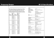
... 1µV Audio Output Power 4 watts Frequency Response 300 to 3000 Hz Distortion Less than 10 dB change in the Citizens Radio Service. CB Freq. SO-239 Meter Indicates relative power output received signal strength TRANSMITTER Power Output 4 watts Modulation AM (Amplitude Modulation) Frequency Response 300 to 50,000 microvolts RF Gain range 40 db Noise Blanker RF type Squelch Adjustable; separate jack provided (SPECIFICATIONS SUBJECT TO...
... 1µV Audio Output Power 4 watts Frequency Response 300 to 3000 Hz Distortion Less than 10 dB change in the Citizens Radio Service. CB Freq. SO-239 Meter Indicates relative power output received signal strength TRANSMITTER Power Output 4 watts Modulation AM (Amplitude Modulation) Frequency Response 300 to 50,000 microvolts RF Gain range 40 db Noise Blanker RF type Squelch Adjustable; separate jack provided (SPECIFICATIONS SUBJECT TO...
Operation Manual
Page 20
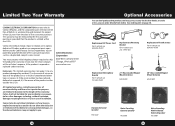
..., defaced or removed; 4) if the owner of a sales receipt. including, without charge, repair or replace, at your local Cobra dealer, or in the event of misuse or abuse of the product or as a duplicated copy of the product resides outside the U.S.A. Replacement DC Power Cord For in vehicle use 426-002-N-001 Replacement Mounting Bracket For in vehicle use 251-199...
..., defaced or removed; 4) if the owner of a sales receipt. including, without charge, repair or replace, at your local Cobra dealer, or in the event of misuse or abuse of the product or as a duplicated copy of the product resides outside the U.S.A. Replacement DC Power Cord For in vehicle use 426-002-N-001 Replacement Mounting Bracket For in vehicle use 251-199...
Operation Manual
Page 21
...'s license. This will either be repaired or exchanged depending on -line in 1949. Cortland St., Chicago, IL 60707. 6. You should require factory service please call Cobra first before sending your unit to send your unit in. Operating Manual 2. DC power cord 3 Transceiver bracket 7. You may cause violation of the technical regulations of Part 95 of the FCC Rules...
...'s license. This will either be repaired or exchanged depending on -line in 1949. Cortland St., Chicago, IL 60707. 6. You should require factory service please call Cobra first before sending your unit to send your unit in. Operating Manual 2. DC power cord 3 Transceiver bracket 7. You may cause violation of the technical regulations of Part 95 of the FCC Rules...
Operation Manual
Page 22
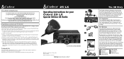
... the Cobra 25 LX CB Radio. For Credit Card Orders Call 773-889-3087 [Press one from the main menu] 8:00 a.m. Make Check or Money Order Payable To Cobra Electronics, Attn: Accessories Dept., 6500 West Cortland Street, Chicago, IL 60707 U.S.A. Dim/Escape Button 8. Signal Strength Meter 14. Antenna Connector 19. This device must accept any problems with part 15...
... the Cobra 25 LX CB Radio. For Credit Card Orders Call 773-889-3087 [Press one from the main menu] 8:00 a.m. Make Check or Money Order Payable To Cobra Electronics, Attn: Accessories Dept., 6500 West Cortland Street, Chicago, IL 60707 U.S.A. Dim/Escape Button 8. Signal Strength Meter 14. Antenna Connector 19. This device must accept any problems with part 15...


