
Hardware Maintenance Manual
Page 3
... the Cisco Service Partner if the Software was paid and the other trademarks, service marks, registered trademarks, or registered service marks mentioned in this manual is subject to restrictions as authorized by Cisco, (2) has not been installed, operated, repaired, or maintained in equipment provided by Cisco and Bringing the power of internetworking to use the Cisco software ("Software") in object code form solely on a straight-line basis...
... the Cisco Service Partner if the Software was paid and the other trademarks, service marks, registered trademarks, or registered service marks mentioned in this manual is subject to restrictions as authorized by Cisco, (2) has not been installed, operated, repaired, or maintained in equipment provided by Cisco and Bringing the power of internetworking to use the Cisco software ("Software") in object code form solely on a straight-line basis...

Hardware Maintenance Manual
Page 5
...Unit Numbering 2-7 Console Port and Auxiliary Port Connection Considerations 2-9 Console Port Connections 2-9 Auxiliary Port Connections 2-9 Network Connection Considerations 2-10 Ethernet Connections 2-10 Token Ring Connections 2-13 Serial Connections 2-15 Fiber Distributed Data Interface Connections 2-25 BRI Connections 2-29 Channelized T1 Connections 2-30 Channelized E1 Connections 2-32 ATM Connections 2-34 Inspecting the System 2-36 Chapter 3 Installing the Router 3-1 Rack-Mount and Wall-Mount Procedures Overview 3-1 Making Console Port Connections 3-1 Making Network Connections 3-2 Table...
...Unit Numbering 2-7 Console Port and Auxiliary Port Connection Considerations 2-9 Console Port Connections 2-9 Auxiliary Port Connections 2-9 Network Connection Considerations 2-10 Ethernet Connections 2-10 Token Ring Connections 2-13 Serial Connections 2-15 Fiber Distributed Data Interface Connections 2-25 BRI Connections 2-29 Channelized T1 Connections 2-30 Channelized E1 Connections 2-32 ATM Connections 2-34 Inspecting the System 2-36 Chapter 3 Installing the Router 3-1 Rack-Mount and Wall-Mount Procedures Overview 3-1 Making Console Port Connections 3-1 Making Network Connections 3-2 Table...

Hardware Maintenance Manual
Page 6
...Power Supply 3-20 Making Final Connections to the Router 3-22 Chapter 4 Troubleshooting the Initial Hardware Configuration 4-1 Problem Solving 4-1 Troubleshooting the Power and Cooling Systems 4-2 Troubleshooting the Network Processor Modules and Cables 4-2 Environmental Reporting Features 4-3 Reading Front-Panel LED Indicators 4-3 System LED Operation 4-3 Reading Network Processor Module LED Indicators 4-4 Ethernet Network Processor Module LED Indicators 4-4 Token Ring Network Processor Module LED Indicators 4-5 Four Port Serial Module Indicators 4-6 Dual Serial Network Processor Module LED...
...Power Supply 3-20 Making Final Connections to the Router 3-22 Chapter 4 Troubleshooting the Initial Hardware Configuration 4-1 Problem Solving 4-1 Troubleshooting the Power and Cooling Systems 4-2 Troubleshooting the Network Processor Modules and Cables 4-2 Environmental Reporting Features 4-3 Reading Front-Panel LED Indicators 4-3 System LED Operation 4-3 Reading Network Processor Module LED Indicators 4-4 Ethernet Network Processor Module LED Indicators 4-4 Token Ring Network Processor Module LED Indicators 4-5 Four Port Serial Module Indicators 4-6 Dual Serial Network Processor Module LED...

Hardware Maintenance Manual
Page 15
... a DC-input power supply. Use this publication follow: • Chapter 1, "Cisco 4000 Series Overview," contains an overview of the Cisco 4000 series features and physical specifications. • Chapter 2, "Preparing for Installation," includes safety recommendations, tools and equipment, site requirements, an installation checklist, console and auxiliary port cable connection considerations, network connection considerations, and instructions for inspecting the new system. • Chapter 3, "Installing the Router," includes instructions for the router installer, who should...
... a DC-input power supply. Use this publication follow: • Chapter 1, "Cisco 4000 Series Overview," contains an overview of the Cisco 4000 series features and physical specifications. • Chapter 2, "Preparing for Installation," includes safety recommendations, tools and equipment, site requirements, an installation checklist, console and auxiliary port cable connection considerations, network connection considerations, and instructions for inspecting the new system. • Chapter 3, "Installing the Router," includes instructions for the router installer, who should...

Hardware Maintenance Manual
Page 16
... LED indicators. • Chapter 5, "Maintaining and Upgrading the Router," includes instructions for opening the chassis, replacing or adding network processor modules, and replacing single in-line memory modules (SIMMs). • Appendix A, "Cabling Specifications," provides cable illustrations, cable pinouts, and signal descriptions for the console and auxiliary ports, synchronous serial cables, and Ethernet (AUI) cables. • Appendix B, "Cisco 4000 Series Virtual Configuration Register," describes the Cisco 4000-M virtual configuration register and procedures for changing the factory...
... LED indicators. • Chapter 5, "Maintaining and Upgrading the Router," includes instructions for opening the chassis, replacing or adding network processor modules, and replacing single in-line memory modules (SIMMs). • Appendix A, "Cabling Specifications," provides cable illustrations, cable pinouts, and signal descriptions for the console and auxiliary ports, synchronous serial cables, and Ethernet (AUI) cables. • Appendix B, "Cisco 4000 Series Virtual Configuration Register," describes the Cisco 4000-M virtual configuration register and procedures for changing the factory...
Hardware Maintenance Manual
Page 24
... power is connected to power lines, remove jewelry (including rings, necklaces, and watches). Performing a software upgrade • Do not work area, such as moist floors, ungrounded power extension cables, and missing safety grounds. • If an electrical accident occurs, proceed as follows: - Use ... area clear and dust-free during and after installation. • Always turn off the power and unplug the power cord. • Disconnect all power supplies off power to the system. - Working near power supplies - Always check. • Look carefully for help to ensure your work alone ...
... power is connected to power lines, remove jewelry (including rings, necklaces, and watches). Performing a software upgrade • Do not work area, such as moist floors, ungrounded power extension cables, and missing safety grounds. • If an electrical accident occurs, proceed as follows: - Use ... area clear and dust-free during and after installation. • Always turn off the power and unplug the power cord. • Disconnect all power supplies off power to the system. - Working near power supplies - Always check. • Look carefully for help to ensure your work alone ...

Hardware Maintenance Manual
Page 28
...-Use the Site Log as a record of ongoing router maintenance and expansion history. Make entries as additional equipment, and most provide either a V.35, EIA/TIA-449, or EIA-530 electrical interface. • Ethernet transceiver. • Token Ring media attachment unit (MAU). • Optical bypass switch or concentrator for multimode Fiber Distributed Data Interface (FDDI) connections. 2-6 Cisco 4000 Series Hardware Installation and Maintenance Additional network processor modules - Configuration changes...
...-Use the Site Log as a record of ongoing router maintenance and expansion history. Make entries as additional equipment, and most provide either a V.35, EIA/TIA-449, or EIA-530 electrical interface. • Ethernet transceiver. • Token Ring media attachment unit (MAU). • Optical bypass switch or concentrator for multimode Fiber Distributed Data Interface (FDDI) connections. 2-6 Cisco 4000 Series Hardware Installation and Maintenance Additional network processor modules - Configuration changes...

Hardware Maintenance Manual
Page 37
Preparing for each serial interface type; Table 2-4 lists the IEEE-recommended maximum speeds and distances for Installation 2-15 however, you may get good results at speeds and distances greater than EIA/TIA-232. generally, the slower the baud rate, the greater the distance. The network end of the adapter cable is commonly used. Network Connection Considerations Serial Connections When setting up to distance limits, beyond which a signal degrades significantly...
Preparing for each serial interface type; Table 2-4 lists the IEEE-recommended maximum speeds and distances for Installation 2-15 however, you may get good results at speeds and distances greater than EIA/TIA-232. generally, the slower the baud rate, the greater the distance. The network end of the adapter cable is commonly used. Network Connection Considerations Serial Connections When setting up to distance limits, beyond which a signal degrades significantly...

Hardware Maintenance Manual
Page 43
... for Installation 2-21 For instance, if the command no dte-invert-timing was previously entered in the configuration file, then dte-invert-timing must use a special serial cable to connect the router to the software publications. Note that the cables for NRZI, move the jumpers to operate as shown in NRZI mode, the sense of the port-for example, if the cable is DTE and the clock rate...
... for Installation 2-21 For instance, if the command no dte-invert-timing was previously entered in the configuration file, then dte-invert-timing must use a special serial cable to connect the router to the software publications. Note that the cables for NRZI, move the jumpers to operate as shown in NRZI mode, the sense of the port-for example, if the cable is DTE and the clock rate...

Hardware Maintenance Manual
Page 45
... software documentation. For complete command descriptions and instructions, refer to decode signals, rather than determining absolute values. If the result is for NRZI encoding: router# configure terminal interface serial 0 nrzi-encoding ^Z To disable NRZI encoding on the Four-Port Serial Module All Cisco 4000 series router serial interfaces support CRC-CCITT, a 16-bit cyclic redundancy check (CRC). The following example shows the output of check digits per frame that uses a calculated numeric value to check the network interface...
... software documentation. For complete command descriptions and instructions, refer to decode signals, rather than determining absolute values. If the result is for NRZI encoding: router# configure terminal interface serial 0 nrzi-encoding ^Z To disable NRZI encoding on the Four-Port Serial Module All Cisco 4000 series router serial interfaces support CRC-CCITT, a 16-bit cyclic redundancy check (CRC). The following example shows the output of check digits per frame that uses a calculated numeric value to check the network interface...

Hardware Maintenance Manual
Page 54
... one channelized E1 connection via a serial cable to a channel service unit (CSU). On the CE1, the controller provides up to 120-ohm or 75-ohm. Each virtual channel is the physical media that can function as stated in Table 2-7. This interface is presented to 120-ohm. 2-32 Cisco 4000 Series Hardware Installation and Maintenance For wide-area networking, the CE1 can be configured individually. To set capacitive...
... one channelized E1 connection via a serial cable to a channel service unit (CSU). On the CE1, the controller provides up to 120-ohm or 75-ohm. Each virtual channel is the physical media that can function as stated in Table 2-7. This interface is presented to 120-ohm. 2-32 Cisco 4000 Series Hardware Installation and Maintenance For wide-area networking, the CE1 can be configured individually. To set capacitive...

Hardware Maintenance Manual
Page 72
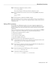
... linecode format. Router(config)# Step 2 At the prompt, specify the controller to configure the new CT1 module. Router(config-controller)# clock source line Note The clock source should be set to use on the new interfaces • Internet protocol (IP) addresses if you replaced the CT1 that the console terminal will determine which end of an existing controller, you verify that follows is used as the channel-group. Be...
... linecode format. Router(config)# Step 2 At the prompt, specify the controller to configure the new CT1 module. Router(config-controller)# clock source line Note The clock source should be set to use on the new interfaces • Internet protocol (IP) addresses if you replaced the CT1 that the console terminal will determine which end of an existing controller, you verify that follows is used as the channel-group. Be...
Hardware Maintenance Manual
Page 73
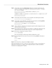
... example: Router(config-if)# ip address 1.1.15.1 255.255.255.0 Router(config-if)# Step 9 Add any additional configuration subcommands required to the interface with show commands. Refer to exit the configuration mode. Router(config-controller)# channel-group 0 timeslots 1,3-5,7 Router(config-controller)# %LINEPROTO-5-UPDOWN: Line protocol on Interface Serial1:0, changed state to down the Control key while you press Z) to the printed Router Products Configuration Guide and Router Products Command Reference publications or UniverCD for mapping. Making Network Connections Step...
... example: Router(config-if)# ip address 1.1.15.1 255.255.255.0 Router(config-if)# Step 9 Add any additional configuration subcommands required to the interface with show commands. Refer to exit the configuration mode. Router(config-controller)# channel-group 0 timeslots 1,3-5,7 Router(config-controller)# %LINEPROTO-5-UPDOWN: Line protocol on Interface Serial1:0, changed state to down the Control key while you press Z) to the printed Router Products Configuration Guide and Router Products Command Reference publications or UniverCD for mapping. Making Network Connections Step...

Hardware Maintenance Manual
Page 74
... routing • Whether the new interface will be mapped. Router(config-controller)# channel-group 0 timeslots 1,3-5,7 Router(config-controller)# %LINEPROTO-5-UPDOWN: Line protocol on Interface Serial1:0, changed state to down the Control key while you press Z) to exit the configuration mode. 3-16 Cisco 4000 Series Hardware Installation and Maintenance Press the Return key after each step. If you must enter the configuration mode. The example that the console terminal will use the privileged-level configure command to configure the new CE1 module...
... routing • Whether the new interface will be mapped. Router(config-controller)# channel-group 0 timeslots 1,3-5,7 Router(config-controller)# %LINEPROTO-5-UPDOWN: Line protocol on Interface Serial1:0, changed state to down the Control key while you press Z) to exit the configuration mode. 3-16 Cisco 4000 Series Hardware Installation and Maintenance Press the Return key after each step. If you must enter the configuration mode. The example that the console terminal will use the privileged-level configure command to configure the new CE1 module...
Hardware Maintenance Manual
Page 75
..., • Static address mappings (address-lists). Refer to the printed Router Products Configuration Guide and Router Products Command Reference publications or UniverCD for a summary of the configuration options available and instructions for SONET interfaces, STS-3c is stored. Making Network Connections Step 9 Write the new configuration to memory as follows: Router# disable Router> Step 11 Check the interface configuration with show a basic ATM configuration using just PVCs. If you replaced the ATM interface that the console terminal will need...
..., • Static address mappings (address-lists). Refer to the printed Router Products Configuration Guide and Router Products Command Reference publications or UniverCD for a summary of the configuration options available and instructions for SONET interfaces, STS-3c is stored. Making Network Connections Step 9 Write the new configuration to memory as follows: Router# disable Router> Step 11 Check the interface configuration with show a basic ATM configuration using just PVCs. If you replaced the ATM interface that the console terminal will need...
Hardware Maintenance Manual
Page 82
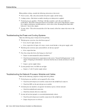
... problem: • With the power switch on, does the blower operate? - Suspect an environmentally induced shutdown. - Check the motherboard connection. - Check the network processor module connection to the motherboard connector. - Suspect a power supply failure. • System partially boots, but interface port(s) will not boot properly or constantly/intermittently reboots. - Check the LEDs on the network processor module. • Network processor module is not recognized by the system. - Suspect the processor or software. 4-2 Cisco 4000 Series Hardware Installation...
... problem: • With the power switch on, does the blower operate? - Suspect an environmentally induced shutdown. - Check the motherboard connection. - Check the network processor module connection to the motherboard connector. - Suspect a power supply failure. • System partially boots, but interface port(s) will not boot properly or constantly/intermittently reboots. - Check the LEDs on the network processor module. • Network processor module is not recognized by the system. - Suspect the processor or software. 4-2 Cisco 4000 Series Hardware Installation...
Hardware Maintenance Manual
Page 113
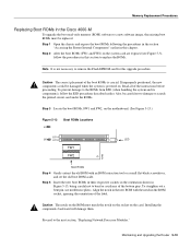
... It is not necessary to remove the Flash EPROM card for this chapter. To straighten out a bent pin, use needlenose pliers. Align the notch in the new ROM with an ROM extraction tool or a small flat-blade screwdriver, and set the old boot ROM aside. Proceed to the next section, "Replacing Network Processor Modules." Installing the components backward will...
... It is not necessary to remove the Flash EPROM card for this chapter. To straighten out a bent pin, use needlenose pliers. Align the notch in the new ROM with an ROM extraction tool or a small flat-blade screwdriver, and set the old boot ROM aside. Proceed to the next section, "Replacing Network Processor Modules." Installing the components backward will...
Hardware Maintenance Manual
Page 117
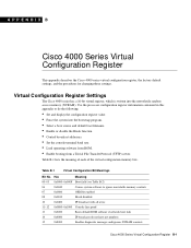
...; Control broadcast addresses. • Set the console terminal baud rate. • Load operating software from ROM. • Enable booting from a Trivial File Transfer Protocol (TFTP) server. Use the processor configuration register information contained in this appendix to ignore nonvolatile memory contents 07 0x0080 OEM bit enabled 08 0x0100 Break disabled 10 0x0400 IP broadcast with all zeros 11-12 0x0800-0x1000 Console line speed 13 0x2000 Boots default ROM software if network boot fails 14...
...; Control broadcast addresses. • Set the console terminal baud rate. • Load operating software from ROM. • Enable booting from a Trivial File Transfer Protocol (TFTP) server. Use the processor configuration register information contained in this appendix to ignore nonvolatile memory contents 07 0x0080 OEM bit enabled 08 0x0100 Break disabled 10 0x0400 IP broadcast with all zeros 11-12 0x0800-0x1000 Console line speed 13 0x2000 Boots default ROM software if network boot fails 14...
Hardware Maintenance Manual
Page 119
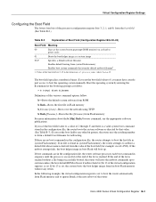
... a file being successfully booted, the router will boot up to netboot a default file whose name is set to boot the router automatically from Flash memory and to form a default boot filename for example: cisco2-4500). Values of the boot field are in the configuration file, the router software processes each boot command in sequence until the process is successful or the end of the list is set . If you must have console port access to boot...
... a file being successfully booted, the router will boot up to netboot a default file whose name is set to boot the router automatically from Flash memory and to form a default boot filename for example: cisco2-4500). Values of the boot field are in the configuration file, the router software processes each boot command in sequence until the process is successful or the end of the list is set . If you must have console port access to boot...

Hardware Maintenance Manual
Page 141
...port A-8 EIA-530 dual-port A-16 four-port A-18 EIA-TIA-232, four-port A-5 Ethernet (AUI) A-19 RJ-45 A-20 serial cable A-3-A-18 Token Ring A-21 V.35 dual-port A-10 four-port A-11 X.21 dual-port A-14 four-port A-15 polarity, Ethernet LED 4-5 port locations 2-7 software configuration, serial 4-8 power LED indication 3-22 light 4-3 specifications 1-3 supply features 2-4 system, troubleshooting 4-2 preparing for installation 2-1 to make connections 2-7 preventing ESD damage 2-3 preventive site configuration 2-4 printing summary of ROM monitor commands problem indications 4-3 temperature 4-3 problem...
...port A-8 EIA-530 dual-port A-16 four-port A-18 EIA-TIA-232, four-port A-5 Ethernet (AUI) A-19 RJ-45 A-20 serial cable A-3-A-18 Token Ring A-21 V.35 dual-port A-10 four-port A-11 X.21 dual-port A-14 four-port A-15 polarity, Ethernet LED 4-5 port locations 2-7 software configuration, serial 4-8 power LED indication 3-22 light 4-3 specifications 1-3 supply features 2-4 system, troubleshooting 4-2 preparing for installation 2-1 to make connections 2-7 preventing ESD damage 2-3 preventive site configuration 2-4 printing summary of ROM monitor commands problem indications 4-3 temperature 4-3 problem...


