
Hardware Maintenance Manual
Page 7
...530 Four-Port Serial Module Cable Assembly A-18 Ethernet Cable Pinouts A-19 Ethernet (AUI) Cable Pinouts A-19 RJ-45 10BaseT Connector Pinouts A-20 Token Ring Port Pinout A-21 BRI Pinout A-22 Channelized T1 Pinouts A-22 Channelized E1 Pinouts A-... Register Settings B-2 Configuring the Boot Field B-3 Enabling Booting from Flash Memory B-6 Appendix C Cisco 4000-M ROM Monitor C-1 Entering the Cisco 4000-M ROM Monitor Program C-1 Available ROM Monitor Commands C-2 Appendix D Cisco 4500-M and Cisco 4700 ROM Monitor D-1 Entering the ROM Monitor Program D-1 Available ROM Monitor Commands D-2 ROM ...
...530 Four-Port Serial Module Cable Assembly A-18 Ethernet Cable Pinouts A-19 Ethernet (AUI) Cable Pinouts A-19 RJ-45 10BaseT Connector Pinouts A-20 Token Ring Port Pinout A-21 BRI Pinout A-22 Channelized T1 Pinouts A-22 Channelized E1 Pinouts A-... Register Settings B-2 Configuring the Boot Field B-3 Enabling Booting from Flash Memory B-6 Appendix C Cisco 4000-M ROM Monitor C-1 Entering the Cisco 4000-M ROM Monitor Program C-1 Available ROM Monitor Commands C-2 Appendix D Cisco 4500-M and Cisco 4700 ROM Monitor D-1 Entering the ROM Monitor Program D-1 Available ROM Monitor Commands D-2 ROM ...

Hardware Maintenance Manual
Page 10
...2-34 E1 Interface Cable for 120-Ohm, Balanced Connections (with Twinax Connectors) 2-34 E1 Interface Cable for 120-Ohm, Balanced Connections (with RJ-45 Connector) 2-34 ATM Network Processor Module with STS-3c/STM-1 Single Mode PLIM 2-35 ATM Network Processor Module with STS-3c/STM-1 ...Multimode FDDI Connections 3-12 Single-Mode Dual-Attachment FDDI Connections 3-13 Cisco 4000 Series DC-Input Power Supply-Rear View 3-20 Cisco 4000 Series AC-Input Power Supply-Rear View 3-20 DC-Input Power Supply Connections 3-21 Cisco 4000 Series-Front Panel Indicators 4-3 Dual-Port Ethernet Network Processor ...
...2-34 E1 Interface Cable for 120-Ohm, Balanced Connections (with Twinax Connectors) 2-34 E1 Interface Cable for 120-Ohm, Balanced Connections (with RJ-45 Connector) 2-34 ATM Network Processor Module with STS-3c/STM-1 Single Mode PLIM 2-35 ATM Network Processor Module with STS-3c/STM-1 ...Multimode FDDI Connections 3-12 Single-Mode Dual-Attachment FDDI Connections 3-13 Cisco 4000 Series DC-Input Power Supply-Rear View 3-20 Cisco 4000 Series AC-Input Power Supply-Rear View 3-20 DC-Input Power Supply Connections 3-21 Cisco 4000 Series-Front Panel Indicators 4-3 Dual-Port Ethernet Network Processor ...

Hardware Maintenance Manual
Page 11
...for Chassis With a Safety Latch 5-3 Component Tray Removal for Chassis Without a Safety Latch 5-4 Typical Cisco 4000 Series Component Tray-Cisco 4000-M Shown 5-5 Network Processor Module Locations 5-6 Cisco 4000-M SIMM Locations 5-7 Cisco 4500-M and Cisco 4700 SIMM Locations 5-8 Cisco 4000 Series Main Memory SIMM 5-8 Removing Main Memory SIMMs 5-10 Installing Main Memory SIMMs 5-12 ...15 Dual Serial Module EIA-530 Cable Assembly A-16 Four-Port Serial Module EIA-530 Cable Assembly A-18 Ethernet (AUI) Cable Assembly A-19 RJ-45 10BaseT Connector A-20 T1 Interface Cable A-22 List of Figures xi
...for Chassis With a Safety Latch 5-3 Component Tray Removal for Chassis Without a Safety Latch 5-4 Typical Cisco 4000 Series Component Tray-Cisco 4000-M Shown 5-5 Network Processor Module Locations 5-6 Cisco 4000-M SIMM Locations 5-7 Cisco 4500-M and Cisco 4700 SIMM Locations 5-8 Cisco 4000 Series Main Memory SIMM 5-8 Removing Main Memory SIMMs 5-10 Installing Main Memory SIMMs 5-12 ...15 Dual Serial Module EIA-530 Cable Assembly A-16 Four-Port Serial Module EIA-530 Cable Assembly A-18 Ethernet (AUI) Cable Assembly A-19 RJ-45 10BaseT Connector A-20 T1 Interface Cable A-22 List of Figures xi

Hardware Maintenance Manual
Page 12
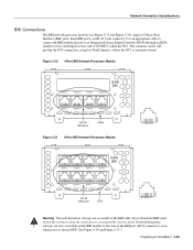
Figure A-14 Figure A-15 Figure A-16 Figure A-17 E1 Interface Cable for 75-Ohm, Unbalanced Connections (with BNC Connectors) A-23 E1 Interface Cable for 120-Ohm, Balanced Connections (with DB-15 Connectors) A-24 E1 Interface Cable for 120-Ohm, Balanced Connections (with Twinax Connectors) A-24 E1 Interface Cable for 120-Ohm, Balanced Connections (with RJ-45 Connector) A-24 xii Cisco 4000 Series Hardware Installation and Maintenance
Figure A-14 Figure A-15 Figure A-16 Figure A-17 E1 Interface Cable for 75-Ohm, Unbalanced Connections (with BNC Connectors) A-23 E1 Interface Cable for 120-Ohm, Balanced Connections (with DB-15 Connectors) A-24 E1 Interface Cable for 120-Ohm, Balanced Connections (with Twinax Connectors) A-24 E1 Interface Cable for 120-Ohm, Balanced Connections (with RJ-45 Connector) A-24 xii Cisco 4000 Series Hardware Installation and Maintenance

Hardware Maintenance Manual
Page 13
... Maximum Transmission Distances 2-25 BRI Cable Specifications 2-30 Jumper Settings and Functions 2-33 BRI Cable Specifications 3-6 BRI Port Pinout (RJ-45) 3-8 Creepage and Clearance Distances Based on Voltage 3-10 Four Port Serial Network Processor Module LED Indicators 4-7 Dual Serial Network ...Processor Module LED Indicators 4-9 Cisco 4000-M Console and Auxiliary Port Signals A-2 Cisco 4500-M and Cisco 4700 Console and Auxiliary Port Signals A-2 Dual Serial Module EIA/TIA-232 DTE and DCE Serial Cable ...
... Maximum Transmission Distances 2-25 BRI Cable Specifications 2-30 Jumper Settings and Functions 2-33 BRI Cable Specifications 3-6 BRI Port Pinout (RJ-45) 3-8 Creepage and Clearance Distances Based on Voltage 3-10 Four Port Serial Network Processor Module LED Indicators 4-7 Dual Serial Network ...Processor Module LED Indicators 4-9 Cisco 4000-M Console and Auxiliary Port Signals A-2 Cisco 4500-M and Cisco 4700 Console and Auxiliary Port Signals A-2 Dual Serial Module EIA/TIA-232 DTE and DCE Serial Cable ...
Hardware Maintenance Manual
Page 14
Table A-21 Table A-22 Table A-23 Table A-24 Table B-1 Table B-2 Table B-3 Table B-4 Table B-5 Table C-1 BRI Port Pinout (RJ-45) A-22 T1 Null-Modem Cable Pinouts (P/N 72-0800-xx) A-23 T1 Straight-Through Cable Pinouts (P/N 72-0799-xx) A-23 E1 Interface Cable Pinouts A-24 ... Field (Configuration Register Bits 00-03) B-3 Default Boot Filenames B-4 Configuration Register Settings for Broadcast Address Destination B-5 System Console Terminal Baud Rate Settings B-5 O Command Options C-3 xiv Cisco 4000 Series Hardware Installation and Maintenance
Table A-21 Table A-22 Table A-23 Table A-24 Table B-1 Table B-2 Table B-3 Table B-4 Table B-5 Table C-1 BRI Port Pinout (RJ-45) A-22 T1 Null-Modem Cable Pinouts (P/N 72-0800-xx) A-23 T1 Straight-Through Cable Pinouts (P/N 72-0799-xx) A-23 E1 Interface Cable Pinouts A-24 ... Field (Configuration Register Bits 00-03) B-3 Default Boot Filenames B-4 Configuration Register Settings for Broadcast Address Destination B-5 System Console Terminal Baud Rate Settings B-5 O Command Options C-3 xiv Cisco 4000 Series Hardware Installation and Maintenance
Hardware Maintenance Manual
Page 51
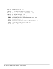
... called the NT1. Figure 2-30 4-Port BRI Network Processor Module PORT-7 PORT-6 PORT-5 PORT-4 ISDN BRI PORT-3 PORT-2 PORT-1 PORT-0 7 6 5 4 3 2 1 0 RJ-45 BRI ports LEDs Figure 2-31 8-Port BRI Network Processor Module 87654321 H2520 PORT-7 PORT-6 PORT-5 ISDN BRI PORT-4 H2412 PORT-3 PORT-2 PORT-1 PORT... are also accessible on the BRI module in the BRI cable. Network hazardous voltages are accessible in the area of the BRI port (RJ-45 connector), even when power is turned OFF. (See Figure 2-30 and Figure 2-31.) Preparing for Installation 2-29 Use an appropriate...
... called the NT1. Figure 2-30 4-Port BRI Network Processor Module PORT-7 PORT-6 PORT-5 PORT-4 ISDN BRI PORT-3 PORT-2 PORT-1 PORT-0 7 6 5 4 3 2 1 0 RJ-45 BRI ports LEDs Figure 2-31 8-Port BRI Network Processor Module 87654321 H2520 PORT-7 PORT-6 PORT-5 ISDN BRI PORT-4 H2412 PORT-3 PORT-2 PORT-1 PORT... are also accessible on the BRI module in the BRI cable. Network hazardous voltages are accessible in the area of the BRI port (RJ-45 connector), even when power is turned OFF. (See Figure 2-30 and Figure 2-31.) Preparing for Installation 2-29 Use an appropriate...

Hardware Maintenance Manual
Page 55
... the potential for 75-Ohm, Unbalanced Connections (with no ground. For either BNC, DB-15, Twinax, or RJ-45 connectors on the network end. For the CE1 module, four serial cables are available from Cisco Systems. All three have DB-15 connectors on the CE1end and either impedance option, a jumper installed at...
... the potential for 75-Ohm, Unbalanced Connections (with no ground. For either BNC, DB-15, Twinax, or RJ-45 connectors on the network end. For the CE1 module, four serial cables are available from Cisco Systems. All three have DB-15 connectors on the CE1end and either impedance option, a jumper installed at...
Hardware Maintenance Manual
Page 56
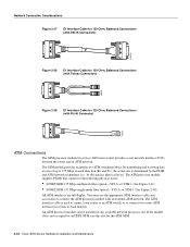
...-Ohm, Balanced Connections (with an external ATM network. The ATM processor module supports PLIMs that connect to connect the ATM processor module with RJ-45 Connector) H2422 ATM Connections The ATM processor module for transmitting and receiving data at rates of up to -back manner. You must...two router ATM interfaces in a back-to 155 Mbps in any available network processor slot. The ATM module provides an interface to ATM switching fabrics for a Cisco 4000 series router provides a user network interface (UNI) between the router and an ATM network. An ATM processor module can be ...
...-Ohm, Balanced Connections (with an external ATM network. The ATM processor module supports PLIMs that connect to connect the ATM processor module with RJ-45 Connector) H2422 ATM Connections The ATM processor module for transmitting and receiving data at rates of up to -back manner. You must...two router ATM interfaces in a back-to 155 Mbps in any available network processor slot. The ATM module provides an interface to ATM switching fabrics for a Cisco 4000 series router provides a user network interface (UNI) between the router and an ATM network. An ATM processor module can be ...

Hardware Maintenance Manual
Page 64
... unit (CSU/DSU). Making Network Connections Caution For proper router operation, both ends of the BRI port (RJ-45 connector) even when power is customer owned. 3-6 Cisco 4000 Series Hardware Installation and Maintenance When all your network connections are not implemented. The BRI module does not...an appropriate cable to connect the BRI module directly to it, must be connected. The common carrier will "flap." The NT1 is an RJ-45 8-pin connector. Only one source (the transmitter) and one sink (the receiver) are also accessible on the network processor module in...
... unit (CSU/DSU). Making Network Connections Caution For proper router operation, both ends of the BRI port (RJ-45 connector) even when power is customer owned. 3-6 Cisco 4000 Series Hardware Installation and Maintenance When all your network connections are not implemented. The BRI module does not...an appropriate cable to connect the BRI module directly to it, must be connected. The common carrier will "flap." The NT1 is an RJ-45 8-pin connector. Only one source (the transmitter) and one sink (the receiver) are also accessible on the network processor module in...

Hardware Maintenance Manual
Page 65
...are also accessible on the BRI module in the BRI cable. Network hazardous voltages are accessible in the area of the BRI port (RJ-45 connector), even when power is turned OFF. (See Figure 3-7 and Figure 3-8.) Figure 3-7 Four-Port BRI Network Processor Module PORT...-7 PORT-6 PORT-5 PORT-4 ISDN BRI PORT-3 PORT-2 PORT-1 PORT-0 7 6 5 4 3 2 1 0 RJ-45 BRI ports LEDs Figure 3-8 Eight-Port BRI Network Processor Module 87654321 H2520 PORT-7 PORT-6 PORT-5 ISDN BRI PORT-4 H2412 PORT-3 PORT-2 PORT-1 PORT...
...are also accessible on the BRI module in the BRI cable. Network hazardous voltages are accessible in the area of the BRI port (RJ-45 connector), even when power is turned OFF. (See Figure 3-7 and Figure 3-8.) Figure 3-7 Four-Port BRI Network Processor Module PORT...-7 PORT-6 PORT-5 PORT-4 ISDN BRI PORT-3 PORT-2 PORT-1 PORT-0 7 6 5 4 3 2 1 0 RJ-45 BRI ports LEDs Figure 3-8 Eight-Port BRI Network Processor Module 87654321 H2520 PORT-7 PORT-6 PORT-5 ISDN BRI PORT-4 H2412 PORT-3 PORT-2 PORT-1 PORT...

Hardware Maintenance Manual
Page 66
... port pinout is shown in a BRI port, use within a range of data communication (gateway and router) chassis supplied by Cisco Systems throughout Europe. Table 3-2 BRI Port Pinout (RJ-45) 8 Pin1 TE2 NT3 Polarity 3 Transmit Receive + 4 Receive Transmit + 5 Receive Transmit - 6 Transmit Receive - ... Host The Cisco Systems Basic Rate Interface (BRI) network processor module is not established on the corresponding port. When not on, the LEDs indicate that provides all of the hardware necessary to either four or eight Basic Access Integrated Switched Digital Networks ...
... port pinout is shown in a BRI port, use within a range of data communication (gateway and router) chassis supplied by Cisco Systems throughout Europe. Table 3-2 BRI Port Pinout (RJ-45) 8 Pin1 TE2 NT3 Polarity 3 Transmit Receive + 4 Receive Transmit + 5 Receive Transmit - 6 Transmit Receive - ... Host The Cisco Systems Basic Rate Interface (BRI) network processor module is not established on the corresponding port. When not on, the LEDs indicate that provides all of the hardware necessary to either four or eight Basic Access Integrated Switched Digital Networks ...

Hardware Maintenance Manual
Page 67
... PTO-provided equipment or connection hardware. The BRI network processor module consists of the following sections before connecting the BRI port of your Cisco Systems dealer will advise). No attempt should only be plugged in lost (nonrecoverable) data packets due to the ISDN while removed from ...module must have a dedicated S-bus connection for each compatible chassis has no other than by a nonremovable, connect one -time-only, nonremovable plug (RJ-45 with host attachments, which are provided by the use of a connect one -time-only plug) must be set up over the digital ...
... PTO-provided equipment or connection hardware. The BRI network processor module consists of the following sections before connecting the BRI port of your Cisco Systems dealer will advise). No attempt should only be plugged in lost (nonrecoverable) data packets due to the ISDN while removed from ...module must have a dedicated S-bus connection for each compatible chassis has no other than by a nonremovable, connect one -time-only, nonremovable plug (RJ-45 with host attachments, which are provided by the use of a connect one -time-only plug) must be set up over the digital ...

Hardware Maintenance Manual
Page 91
... 4-13 Eight-Port BRI Network Processor Module PORT-7 PORT-6 PORT-5 ISDN BRI PORT-4 PORT-3 PORT-2 PORT-1 PORT-0 7 6 5 4 3 2 1 0 RJ-45 BRI ports LEDs Figure 4-14 Four-Port BRI Network Processor Module 87654321 H2412 PORT-7 PORT-6 PORT-5 PORT-4 ISDN BRI PORT-3 PORT-2 PORT-1 PORT...-0 7 6 5 4 3 2 1 0 RJ-45 BRI ports LEDs 87654321 H2520 Troubleshooting the Initial Hardware Configuration 4-11 When off, the LEDs indicate that the link is not established on ...
... 4-13 Eight-Port BRI Network Processor Module PORT-7 PORT-6 PORT-5 ISDN BRI PORT-4 PORT-3 PORT-2 PORT-1 PORT-0 7 6 5 4 3 2 1 0 RJ-45 BRI ports LEDs Figure 4-14 Four-Port BRI Network Processor Module 87654321 H2412 PORT-7 PORT-6 PORT-5 PORT-4 ISDN BRI PORT-3 PORT-2 PORT-1 PORT...-0 7 6 5 4 3 2 1 0 RJ-45 BRI ports LEDs 87654321 H2520 Troubleshooting the Initial Hardware Configuration 4-11 When off, the LEDs indicate that the link is not established on ...
Hardware Maintenance Manual
Page 137
... ATM cabling 2-35 network processor module 2-34 autopolarity 4-5 AUX See auxiliary port auxiliary port connections 2-9 location 2-7 pinouts A-2 RJ-45 connector caution 3-8, A-22 B b command (boot) C-2 Basic Rate Interface See BRI boot command D-3 boot ROMs, replacing ...5-19 booting from Flash B-6 from the ROM monitor Cisco 4000-M C-2 Cisco 4500-M D-3 Cisco 4700 D-3 bootstrap clear memory contents C-2 stack trace, system software C-2 Break key (interrupt) C-1, D-1 BRI distance limitations 2-30, 3-6 making ...
... ATM cabling 2-35 network processor module 2-34 autopolarity 4-5 AUX See auxiliary port auxiliary port connections 2-9 location 2-7 pinouts A-2 RJ-45 connector caution 3-8, A-22 B b command (boot) C-2 Basic Rate Interface See BRI boot command D-3 boot ROMs, replacing ...5-19 booting from Flash B-6 from the ROM monitor Cisco 4000-M C-2 Cisco 4500-M D-3 Cisco 4700 D-3 bootstrap clear memory contents C-2 stack trace, system software C-2 Break key (interrupt) C-1, D-1 BRI distance limitations 2-30, 3-6 making ...

Hardware Maintenance Manual
Page 138
...-M D-4 Cisco 4700 D-4 displaying settings C-3 resetting C-3 confreg command D-4 connections 10BaseT 2-10 9-pin D-type 3-2 auxiliary port 2-9 considerations when making 2-10 console port 2-9 Ethernet attaching to network 3-3 port, considerations 2-12 final 3-22 NT1 3-6 optical bypass switch 3-13 power 3-22 preparing to make 2-7 serial 3-5 Token Ring 2-13, 3-2 console cable, pinout A-2 port alarm message 4-3 connections 2-9 console port RJ...
...-M D-4 Cisco 4700 D-4 displaying settings C-3 resetting C-3 confreg command D-4 connections 10BaseT 2-10 9-pin D-type 3-2 auxiliary port 2-9 considerations when making 2-10 console port 2-9 Ethernet attaching to network 3-3 port, considerations 2-12 final 3-22 NT1 3-6 optical bypass switch 3-13 power 3-22 preparing to make 2-7 serial 3-5 Token Ring 2-13, 3-2 console cable, pinout A-2 port alarm message 4-3 connections 2-9 console port RJ...

Hardware Maintenance Manual
Page 141
...o command (configuration register options) C-3 o/r command (reset) C-3 opening the chassis 5-1 operating conditions European Community F-1 temperature 1-3 operating conditions United Kingdom E-1 optical bypass switch connecting to 3-13 uses 2-28 ordering publications xv overview, series 1-1 P packing list 2-36 pinouts auxiliary port A-2 BRI 3-8, A-22 console port A-2 EIA/TIA...port A-7 four-port A-8 EIA-530 dual-port A-16 four-port A-18 EIA-TIA-232, four-port A-5 Ethernet (AUI) A-19 RJ-45 A-20 serial cable A-3-A-18 Token Ring A-21 V.35 dual-port A-10 four-port A-11 X.21 dual-port A-14 four-port...
...o command (configuration register options) C-3 o/r command (reset) C-3 opening the chassis 5-1 operating conditions European Community F-1 temperature 1-3 operating conditions United Kingdom E-1 optical bypass switch connecting to 3-13 uses 2-28 ordering publications xv overview, series 1-1 P packing list 2-36 pinouts auxiliary port A-2 BRI 3-8, A-22 console port A-2 EIA/TIA...port A-7 four-port A-8 EIA-530 dual-port A-16 four-port A-18 EIA-TIA-232, four-port A-5 Ethernet (AUI) A-19 RJ-45 A-20 serial cable A-3-A-18 Token Ring A-21 V.35 dual-port A-10 four-port A-11 X.21 dual-port A-14 four-port...
Hardware Maintenance Manual
Page 142
...registers, software configuration B-1 reinitializing hardware C-2 reload command B-2 removing network processor modules 5-4 shared-memory SIMMs 5-13 replacing Cisco 4000-M boot ROMs 5-19 component tray 5-20 network processor modules 5-20 shared-memory SIMMs 5-14 system-memory SIMMs...D-3 resetting virtual configuration register C-3 RFI implications 2-18 ring speed 4-5 RJ-45, cable pinout A-20 ROM monitor commands Cisco 4000-M C-2 Cisco 4500-M D-2 Cisco 4700 D-2 diagnostics C-3-C-4, D-4 entering Cisco 4000-M C-1 Cisco 4500-M D-1 Cisco 4700 D-1 exiting C-2 prompt (>) C-1 ROM, replacing boot ROMs 5-...
...registers, software configuration B-1 reinitializing hardware C-2 reload command B-2 removing network processor modules 5-4 shared-memory SIMMs 5-13 replacing Cisco 4000-M boot ROMs 5-19 component tray 5-20 network processor modules 5-20 shared-memory SIMMs 5-14 system-memory SIMMs...D-3 resetting virtual configuration register C-3 RFI implications 2-18 ring speed 4-5 RJ-45, cable pinout A-20 ROM monitor commands Cisco 4000-M C-2 Cisco 4500-M D-2 Cisco 4700 D-2 diagnostics C-3-C-4, D-4 entering Cisco 4000-M C-1 Cisco 4500-M D-1 Cisco 4700 D-1 exiting C-2 prompt (>) C-1 ROM, replacing boot ROMs 5-...