Software Guide
Page 31
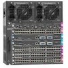
... sections: • Catalyst 4000 Series Switches, page 1-1 • Catalyst 2948G Switch, page 1-2 • Catalyst 2980G Switch, page 1-3 • Supervisor Engine Software, page 1-3 Catalyst 4000 Series Switches Note For installation information and a complete description of media. Table 1-1 Catalyst 4000 Series and Catalyst 4500 Series Switches Product Number Catalyst 4000 Series WS-C4003 WS-C4006 Chassis Description Catalyst 4003 • Modular 3-slot chassis • Optional redundant power supplies Catalyst 4006 •...
... sections: • Catalyst 4000 Series Switches, page 1-1 • Catalyst 2948G Switch, page 1-2 • Catalyst 2980G Switch, page 1-3 • Supervisor Engine Software, page 1-3 Catalyst 4000 Series Switches Note For installation information and a complete description of media. Table 1-1 Catalyst 4000 Series and Catalyst 4500 Series Switches Product Number Catalyst 4000 Series WS-C4003 WS-C4006 Chassis Description Catalyst 4003 • Modular 3-slot chassis • Optional redundant power supplies Catalyst 4006 •...
Software Guide
Page 32
Catalyst 2948G Switch Chapter 1 Product Overview Table 1-1 Catalyst 4000 Series and Catalyst 4500 Series Switches (continued) Product Number WS-C4912G Catalyst 4500 Series WS-C4503 WS-C4506 Chassis Description Catalyst 4912G • Fixed-configuration switch • 12-Gbps backplane • Optional redundant power supplies • 12 1000BASE-X (GBIC) Gigabit Ethernet ports Catalyst 4503 • Modular 3-slot chassis • 28-Gbps full duplex backplane • Optional redundant power...
Catalyst 2948G Switch Chapter 1 Product Overview Table 1-1 Catalyst 4000 Series and Catalyst 4500 Series Switches (continued) Product Number WS-C4912G Catalyst 4500 Series WS-C4503 WS-C4506 Chassis Description Catalyst 4912G • Fixed-configuration switch • 12-Gbps backplane • Optional redundant power supplies • 12 1000BASE-X (GBIC) Gigabit Ethernet ports Catalyst 4503 • Modular 3-slot chassis • 28-Gbps full duplex backplane • Optional redundant power...

Software Guide
Page 33
...Table 1-3 describes the Catalyst 2980G switch. Table 1-3 Catalyst 2980G Switch Product Number WS-C2980G-A Chassis Description Catalyst 2980G • Fixed-configuration switch • 12-Gbps...Catalyst 2948G and 2980G Installation Guide. The Catalyst enterprise LAN switches share a command-line interface (CLI) with which is factory installed on the module. For descriptions of the Catalyst 2980G switch hardware, refer to the Catalyst 4500 Series, Catalyst 2948G, and Catalyst 2980G Switches Command Reference. 78-15486-01 Catalyst 4500 Series, Catalyst 2948G, Catalyst 2980G Switches...
...Table 1-3 describes the Catalyst 2980G switch. Table 1-3 Catalyst 2980G Switch Product Number WS-C2980G-A Chassis Description Catalyst 2980G • Fixed-configuration switch • 12-Gbps...Catalyst 2948G and 2980G Installation Guide. The Catalyst enterprise LAN switches share a command-line interface (CLI) with which is factory installed on the module. For descriptions of the Catalyst 2980G switch hardware, refer to the Catalyst 4500 Series, Catalyst 2948G, and Catalyst 2980G Switches Command Reference. 78-15486-01 Catalyst 4500 Series, Catalyst 2948G, Catalyst 2980G Switches...

Software Guide
Page 76
...Configuring VLAN Trunks on PAgP and LACP EtherChannel ports. Hardware Support for EtherChannel EtherChannel support is 126 for a 6-slot chassis. Due to eight ports. PAgP and LACP Port Aggregation Control Protocol (PAgP) and Link Aggregation Control Protocol (LACP) ... method is a Cisco-proprietary protocol that conform to eight compatibly configured Fast or Gigabit Ethernet ports on page 6-5. Catalyst 4500 Series, Catalyst 2948G, Catalyst 2980G Switches Software Configuration Guide-Release 8.1 6-2 78-15486-01 In addition, on the Catalyst 4500 series switches, you can form...
...Configuring VLAN Trunks on PAgP and LACP EtherChannel ports. Hardware Support for EtherChannel EtherChannel support is 126 for a 6-slot chassis. Due to eight ports. PAgP and LACP Port Aggregation Control Protocol (PAgP) and Link Aggregation Control Protocol (LACP) ... method is a Cisco-proprietary protocol that conform to eight compatibly configured Fast or Gigabit Ethernet ports on page 6-5. Catalyst 4500 Series, Catalyst 2948G, Catalyst 2980G Switches Software Configuration Guide-Release 8.1 6-2 78-15486-01 In addition, on the Catalyst 4500 series switches, you can form...

Software Guide
Page 110
... same configuration in different parts of the root bridge after you migrate your supervisor engine from a Catalyst 4006 switch to a Catalyst 4500 series switch, see the "Migrating a Supervisor Engine II from 1 to 802.1Q. Understanding How MST Works...Catalyst 4500 series switch with the same MST configuration information, allowing them to a Catalyst 4500 Series Switch" section on the Catalyst 4500 series switches; this case, the spanning tree topology does not change after you replace the chassis with 802.1D STP, 802.1w, the Rapid Spanning Tree Protocol (RSTP), and the Cisco...
... same configuration in different parts of the root bridge after you migrate your supervisor engine from a Catalyst 4006 switch to a Catalyst 4500 series switch, see the "Migrating a Supervisor Engine II from 1 to 802.1Q. Understanding How MST Works...Catalyst 4500 series switch with the same MST configuration information, allowing them to a Catalyst 4500 Series Switch" section on the Catalyst 4500 series switches; this case, the spanning tree topology does not change after you replace the chassis with 802.1D STP, 802.1w, the Rapid Spanning Tree Protocol (RSTP), and the Cisco...

Software Guide
Page 375
...Root Trap-Rec-Address 172.16.10.10 172.16.10.20 Console> (enable) Trap-Rec-Community read-write read -write-all | auth | bridge | chassis | config | entity | entityfru | envfan | envpower | envshutdown | envtemp | flashinsert | flashremove | ippermit | module | stpx | syslog | system | ...Step 3 Step 4 Task Command Define the SNMP community strings for the community string). 78-15486-01 Catalyst 4500 Series, Catalyst 2948G, Catalyst 2980G Switches Software Configuration Guide-Release 8.1 24-7 rcvr_port] [owner rcvr_owner] [index rcvr_index] Specify the SNMP traps to send to...
...Root Trap-Rec-Address 172.16.10.10 172.16.10.20 Console> (enable) Trap-Rec-Community read-write read -write-all | auth | bridge | chassis | config | entity | entityfru | envfan | envpower | envshutdown | envtemp | flashinsert | flashremove | ippermit | module | stpx | syslog | system | ...Step 3 Step 4 Task Command Define the SNMP community strings for the community string). 78-15486-01 Catalyst 4500 Series, Catalyst 2948G, Catalyst 2980G Switches Software Configuration Guide-Release 8.1 24-7 rcvr_port] [owner rcvr_owner] [index rcvr_index] Specify the SNMP traps to send to...

Software Guide
Page 388
...). Console> (enable) show snmp RMON: Enabled Extended RMON: Extended RMON module is not present Traps Enabled: Port,Module,Chassis,Bridge,Repeater,Vtp,Auth,ippermit,Vmps,config,entity,stpx Port Traps Enabled: 1/1-2,4/1-48,5/1 Community-Access Community-String read-only Everyone ...Console> (enable) Viewing RMON Data Access to RMON data is disabled by the supervisor engine software. 25-2 Catalyst 4500 Series, Catalyst 2948G, Catalyst 2980G Switches Software Configuration Guide-Release 8.1 78-15486-01 Command set snmp rmon enable SNMP RMON support enabled. You cannot...
...). Console> (enable) show snmp RMON: Enabled Extended RMON: Extended RMON module is not present Traps Enabled: Port,Module,Chassis,Bridge,Repeater,Vtp,Auth,ippermit,Vmps,config,entity,stpx Port Traps Enabled: 1/1-2,4/1-48,5/1 Community-Access Community-String read-only Everyone ...Console> (enable) Viewing RMON Data Access to RMON data is disabled by the supervisor engine software. 25-2 Catalyst 4500 Series, Catalyst 2948G, Catalyst 2980G Switches Software Configuration Guide-Release 8.1 78-15486-01 Command set snmp rmon enable SNMP RMON support enabled. You cannot...

Software Guide
Page 412
...current date and time. After entering the ending delimiter, press Return. To set banner motd c message_of_the_day c - 27-4 Catalyst 4500 Series, Catalyst 2948G, Catalyst 2980G Switches Software Configuration Guide-Release 8.1 78-15486-01 Display the login banner by logging out and logging back in privileged mode: ...Network Time Protocol (NTP). Setting the System Clock Chapter 27 Administering the Switch disable 9600 0% 0% Wed Apr 24 2002, 15:46:01 Power Capacity of the Chassis:2 supplies WARNING:Power supplies of different values have been inserted System Name ...
...current date and time. After entering the ending delimiter, press Return. To set banner motd c message_of_the_day c - 27-4 Catalyst 4500 Series, Catalyst 2948G, Catalyst 2980G Switches Software Configuration Guide-Release 8.1 78-15486-01 Display the login banner by logging out and logging back in privileged mode: ...Network Time Protocol (NTP). Setting the System Clock Chapter 27 Administering the Switch disable 9600 0% 0% Wed Apr 24 2002, 15:46:01 Power Capacity of the Chassis:2 supplies WARNING:Power supplies of different values have been inserted System Name ...

Software Guide
Page 423
... requirements when a system boots. Chapter 28 Power Management Understanding How Power Management Works on page 28-4 for a list of the maximum available power for chassis and inline power for each power supply. 78-15486-01 Catalyst 4500 Series, Catalyst 2948G, Catalyst 2980G Switches Software Configuration Guide-Release 8.1 28-3 Your switch will not have a predetermined current sharing ratio.
... requirements when a system boots. Chapter 28 Power Management Understanding How Power Management Works on page 28-4 for a list of the maximum available power for chassis and inline power for each power supply. 78-15486-01 Catalyst 4500 Series, Catalyst 2948G, Catalyst 2980G Switches Software Configuration Guide-Release 8.1 28-3 Your switch will not have a predetermined current sharing ratio.

Software Guide
Page 424
... for the supervisor engine(s), all line cards, and the fan tray. 2. The backplane consumes 10 W in both redundant and combined mode. 3. The chassis power includes power for the Catalyst 4500 series switches. The DC input can set the power requirements for the installed modules to exceed the power that is configurable. Note To compute...
... for the supervisor engine(s), all line cards, and the fan tray. 2. The backplane consumes 10 W in both redundant and combined mode. 3. The chassis power includes power for the Catalyst 4500 series switches. The DC input can set the power requirements for the installed modules to exceed the power that is configurable. Note To compute...

Software Guide
Page 425
...continues to draw power as long as faulty, even if the main power is working properly. 78-15486-01 Catalyst 4500 Series, Catalyst 2948G, Catalyst 2980G Switches Software Configuration Guide-Release 8.1 28-5 For more modules are drawing power from the system, the power to the...have only one or more information, refer to the Catalyst 4500 Series, Catalyst 2948G, and Catalyst 2980G Switches Command Reference. • Software automatically adjusts between system power (for inline power. The inline power is installed in the chassis. 1400 W DC Power Supply Guidelines and Restrictions This...
...continues to draw power as long as faulty, even if the main power is working properly. 78-15486-01 Catalyst 4500 Series, Catalyst 2948G, Catalyst 2980G Switches Software Configuration Guide-Release 8.1 28-5 For more modules are drawing power from the system, the power to the...have only one or more information, refer to the Catalyst 4500 Series, Catalyst 2948G, and Catalyst 2980G Switches Command Reference. • Software automatically adjusts between system power (for inline power. The inline power is installed in the chassis. 1400 W DC Power Supply Guidelines and Restrictions This...

Software Guide
Page 426
... power usage for the Catalyst 4500 series switches, see the "Understanding How Power Management Works on the Catalyst 4500 Series Switches" section on a reduced number of the system. If you use AC-input and DC-input power supplies in the same chassis. You need to leave... redundancy mode in these hardware configurations: • One Catalyst 4006 chassis with a WS-X4013 supervisor engine with two 400 W power supplies (in 1+1 redundancy mode) and four WS-X4148-RJ or WS-X4148-RJ21 modules • One Catalyst 4006 chassis with a WS-X4013 supervisor engine with two 650 W power supplies ...
... power usage for the Catalyst 4500 series switches, see the "Understanding How Power Management Works on the Catalyst 4500 Series Switches" section on a reduced number of the system. If you use AC-input and DC-input power supplies in the same chassis. You need to leave... redundancy mode in these hardware configurations: • One Catalyst 4006 chassis with a WS-X4013 supervisor engine with two 400 W power supplies (in 1+1 redundancy mode) and four WS-X4148-RJ or WS-X4148-RJ21 modules • One Catalyst 4006 chassis with a WS-X4013 supervisor engine with two 650 W power supplies ...

Software Guide
Page 427
... Modules" section on the switch again, the module(s) in the chassis (at boot up the power that is consumed by the power that require more power than the single power supply provides, the switch places the newly inserted module into reset mode. 78-15486-01 Catalyst 4500 Series, Catalyst 2948G, Catalyst 2980G Switches Software Configuration Guide-Release 8.1 28...
... Modules" section on the switch again, the module(s) in the chassis (at boot up the power that is consumed by the power that require more power than the single power supply provides, the switch places the newly inserted module into reset mode. 78-15486-01 Catalyst 4500 Series, Catalyst 2948G, Catalyst 2980G Switches Software Configuration Guide-Release 8.1 28...

Software Guide
Page 428
... and cannot be used in slots 4 and 5-90 W each (600 W total) • Fan tray-25 W 28-8 Catalyst 4500 Series, Catalyst 2948G, Catalyst 2980G Switches Software Configuration Guide-Release 8.1 78-15486-01 Modules that it is stable and no more power than a single 400 W power ...WS-X4448-GB-LX modules in 1+1 redundancy mode for a 400 W power supply. however, the switch still has only 400 W available. The supervisor engine always remains enabled. The following configuration requires more evaluation cycles are placed into service; If you configure the chassis correctly, the switch...
... and cannot be used in slots 4 and 5-90 W each (600 W total) • Fan tray-25 W 28-8 Catalyst 4500 Series, Catalyst 2948G, Catalyst 2980G Switches Software Configuration Guide-Release 8.1 78-15486-01 Modules that it is stable and no more power than a single 400 W power ...WS-X4448-GB-LX modules in 1+1 redundancy mode for a 400 W power supply. however, the switch still has only 400 W available. The supervisor engine always remains enabled. The following configuration requires more evaluation cycles are placed into service; If you configure the chassis correctly, the switch...
Software Guide
Page 430
...; The Catalyst 4006 switch is a root switch In this case, the spanning tree topology may not be 32,789. If you insert the supervisor engine into the Catalyst 4500 series chassis. If the other switches in the same manner as bridge identifiers; If the switch is added to reflect the new root switch. 28-10 Catalyst 4500 Series, Catalyst 2948G, Catalyst 2980G Switches Software...
...; The Catalyst 4006 switch is a root switch In this case, the spanning tree topology may not be 32,789. If you insert the supervisor engine into the Catalyst 4500 series chassis. If the other switches in the same manner as bridge identifiers; If the switch is added to reflect the new root switch. 28-10 Catalyst 4500 Series, Catalyst 2948G, Catalyst 2980G Switches Software...

Software Guide
Page 431
...-9). 78-15486-01 Catalyst 4500 Series, Catalyst 2948G, Catalyst 2980G Switches Software Configuration Guide-Release 8.1 28-11 The WS-X4148-RJ45V switching modules can power only one device for each module. • Total available inline power that are connected to other Catalyst switching modules, refer to an inline power module. The Catalyst 4006 switch and the Catalyst 4500 series switches can set each port...
...-9). 78-15486-01 Catalyst 4500 Series, Catalyst 2948G, Catalyst 2980G Switches Software Configuration Guide-Release 8.1 28-11 The WS-X4148-RJ45V switching modules can power only one device for each module. • Total available inline power that are connected to other Catalyst switching modules, refer to an inline power module. The Catalyst 4006 switch and the Catalyst 4500 series switches can set each port...

Software Guide
Page 437
...-C45-1000AC Modem Baud Traffic Peak Peak-Time disable 9600 0% 0% Fri May 31 2002, 10:24:04 Power Capacity of the Chassis: 1 supply 78-15486-01 Catalyst 4500 Series, Catalyst 2948G, Catalyst 2980G Switches Software Configuration Guide-Release 8.1 28-17 Command show environment power Total Inline Power Available:0 Watt Total Inline Power Drawn From the System...
...-C45-1000AC Modem Baud Traffic Peak Peak-Time disable 9600 0% 0% Fri May 31 2002, 10:24:04 Power Capacity of the Chassis: 1 supply 78-15486-01 Catalyst 4500 Series, Catalyst 2948G, Catalyst 2980G Switches Software Configuration Guide-Release 8.1 28-17 Command show environment power Total Inline Power Available:0 Watt Total Inline Power Drawn From the System...

Software Guide
Page 441
... Requirements, page 29-1 • Overview of inline power per module. 78-15486-01 Catalyst 4500 Series, Catalyst 2948G, Catalyst 2980G Switches Software Configuration Guide-Release 8.1 29-1 Table 29-1 Catalyst 4500 Series Components Supporting Inline Power Switch Chassis Catalyst 4006 Catalyst 4503 Catalyst 4506 Modules WS-X4148-RJ45V1 WS-X4148-RJ45V Power Supplies Catalyst 4000 Family Power Entry Module (PEM) 1300 W AC 2800 W AC 1400 W DC...
... Requirements, page 29-1 • Overview of inline power per module. 78-15486-01 Catalyst 4500 Series, Catalyst 2948G, Catalyst 2980G Switches Software Configuration Guide-Release 8.1 29-1 Table 29-1 Catalyst 4500 Series Components Supporting Inline Power Switch Chassis Catalyst 4006 Catalyst 4503 Catalyst 4506 Modules WS-X4148-RJ45V1 WS-X4148-RJ45V Power Supplies Catalyst 4000 Family Power Entry Module (PEM) 1300 W AC 2800 W AC 1400 W DC...
Software Guide
Page 555
... a result, traffic coming in this chapter, refer to the Catalyst 4500 Series, Catalyst 2948G, and Catalyst 2980G Switches Command Reference. This chapter consists of these switch engines as SE1, SE2, and SE3. • SE1 handles traffic for Gigabit Ethernet uplink port 1/1 and traffic between modules installed in the chassis. • SE3 handles traffic for Gigabit Ethernet uplink...
... a result, traffic coming in this chapter, refer to the Catalyst 4500 Series, Catalyst 2948G, and Catalyst 2980G Switches Command Reference. This chapter consists of these switch engines as SE1, SE2, and SE3. • SE1 handles traffic for Gigabit Ethernet uplink port 1/1 and traffic between modules installed in the chassis. • SE3 handles traffic for Gigabit Ethernet uplink...

