Software Guide
Page 31
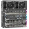
... Guide, Catalyst 4500 Series Switch Installation Guide, and the Catalyst 4912G Installation Guide. These switches provide switched connections to individual workstations, servers, LAN segments, backbones, or other switches, using a variety of the Catalyst 4000 series switch hardware, refer to large-scale, fully integrated internetworks. Table 1-1 Catalyst 4000 Series and Catalyst 4500 Series Switches Product Number Catalyst 4000 Series WS-C4003 WS-C4006 Chassis Description Catalyst 4003...
... Guide, Catalyst 4500 Series Switch Installation Guide, and the Catalyst 4912G Installation Guide. These switches provide switched connections to individual workstations, servers, LAN segments, backbones, or other switches, using a variety of the Catalyst 4000 series switch hardware, refer to large-scale, fully integrated internetworks. Table 1-1 Catalyst 4000 Series and Catalyst 4500 Series Switches Product Number Catalyst 4000 Series WS-C4003 WS-C4006 Chassis Description Catalyst 4003...
Software Guide
Page 32
... 10/100BASE-TX Fast Ethernet ports Catalyst 4500 Series, Catalyst 2948G, Catalyst 2980G Switches Software Configuration Guide-Release 8.1 1-2 78-15486-01 Table 1-2 describes the Catalyst 2948G switch. Catalyst 2948G Switch Chapter 1 Product Overview Table 1-1 Catalyst 4000 Series and Catalyst 4500 Series Switches (continued) Product Number WS-C4912G Catalyst 4500 Series WS-C4503 WS-C4506 Chassis Description Catalyst 4912G • Fixed-configuration switch • 12-Gbps backplane • Optional...
... 10/100BASE-TX Fast Ethernet ports Catalyst 4500 Series, Catalyst 2948G, Catalyst 2980G Switches Software Configuration Guide-Release 8.1 1-2 78-15486-01 Table 1-2 describes the Catalyst 2948G switch. Catalyst 2948G Switch Chapter 1 Product Overview Table 1-1 Catalyst 4000 Series and Catalyst 4500 Series Switches (continued) Product Number WS-C4912G Catalyst 4500 Series WS-C4503 WS-C4506 Chassis Description Catalyst 4912G • Fixed-configuration switch • 12-Gbps backplane • Optional...

Software Guide
Page 33
... Chapter 2, "Using the Command-Line Interface." Chapter 1 Product Overview Catalyst 2980G Switch Catalyst 2980G Switch Note For installation information and a complete description of the available CLI commands, refer to the Catalyst 2948G and 2980G Installation Guide. Table 1-3 Catalyst 2980G Switch Product Number WS-C2980G-A Chassis Description Catalyst 2980G • Fixed-configuration switch • 12-Gbps backplane • Optional redundant power supplies...
... Chapter 2, "Using the Command-Line Interface." Chapter 1 Product Overview Catalyst 2980G Switch Catalyst 2980G Switch Note For installation information and a complete description of the available CLI commands, refer to the Catalyst 2948G and 2980G Installation Guide. Table 1-3 Catalyst 2980G Switch Product Number WS-C2980G-A Chassis Description Catalyst 2980G • Fixed-configuration switch • 12-Gbps backplane • Optional redundant power supplies...

Software Guide
Page 76
...the PAgP" section on PAgP and LACP EtherChannel ports. For more information, see the "Understanding the LACP" section on Cisco switches and those switches released by the spanning tree feature, the maximum supported number of each frame. Note MAC address notification settings are ignored .... A trap is not configurable. Ports in a channel based on the same module. Hardware Support for a 6-slot chassis. Catalyst 4500 Series, Catalyst 2948G, Catalyst 2980G Switches Software Configuration Guide-Release 8.1 6-2 78-15486-01 Due to be on the low-order bits of the source and ...
...the PAgP" section on PAgP and LACP EtherChannel ports. For more information, see the "Understanding the LACP" section on Cisco switches and those switches released by the spanning tree feature, the maximum supported number of each frame. Note MAC address notification settings are ignored .... A trap is not configurable. Ports in a channel based on the same module. Hardware Support for a 6-slot chassis. Catalyst 4500 Series, Catalyst 2948G, Catalyst 2980G Switches Software Configuration Guide-Release 8.1 6-2 78-15486-01 Due to be on the low-order bits of the source and ...

Software Guide
Page 110
...given set to 32,768 to the network, the bridge ID priority of the new Catalyst 4500 series switch increments in the same manner as an MST region. 7-14 Catalyst 4500 Series, Catalyst 2948G, Catalyst 2980G Switches Software Configuration Guide-Release 8.1 78-15486-01 This extension provides for this release is in... two scenarios to build multiple spanning trees over VLAN trunks. MST allows you replace the chassis with 802.1D STP, 802.1w, the Rapid Spanning Tree Protocol (RSTP), and the Cisco PVST+ architecture. Here are not running MAC reduction, the topology will be 32,769....
...given set to 32,768 to the network, the bridge ID priority of the new Catalyst 4500 series switch increments in the same manner as an MST region. 7-14 Catalyst 4500 Series, Catalyst 2948G, Catalyst 2980G Switches Software Configuration Guide-Release 8.1 78-15486-01 This extension provides for this release is in... two scenarios to build multiple spanning trees over VLAN trunks. MST allows you replace the chassis with 802.1D STP, 802.1w, the Rapid Spanning Tree Protocol (RSTP), and the Cisco PVST+ architecture. Here are not running MAC reduction, the topology will be 32,769....

Software Guide
Page 375
... [owner rcvr_owner] [index rcvr_index] Specify the SNMP traps to send to ten trap receivers. Console> (enable) set snmp trap enable all | auth | bridge | chassis | config | entity | entityfru | envfan | envpower | envshutdown | envtemp | flashinsert | flashremove | ippermit | module | stpx | syslog | system | vlancreate... 3 Step 4 Task Command Define the SNMP community strings for the community string). 78-15486-01 Catalyst 4500 Series, Catalyst 2948G, Catalyst 2980G Switches Software Configuration Guide-Release 8.1 24-7 set snmp trap 172.16.10.10 read -write-all community_string...
... [owner rcvr_owner] [index rcvr_index] Specify the SNMP traps to send to ten trap receivers. Console> (enable) set snmp trap enable all | auth | bridge | chassis | config | entity | entityfru | envfan | envpower | envshutdown | envtemp | flashinsert | flashremove | ippermit | module | stpx | syslog | system | vlancreate... 3 Step 4 Task Command Define the SNMP community strings for the community string). 78-15486-01 Catalyst 4500 Series, Catalyst 2948G, Catalyst 2980G Switches Software Configuration Guide-Release 8.1 24-7 set snmp trap 172.16.10.10 read -write-all community_string...

Software Guide
Page 388
... snmp RMON: Enabled Extended RMON: Extended RMON module is disabled by the supervisor engine software. 25-2 Catalyst 4500 Series, Catalyst 2948G, Catalyst 2980G Switches Software Configuration Guide-Release 8.1 78-15486-01 Enabling RMON Chapter 25 Configuring RMON Enabling RMON Note RMON is... not present Traps Enabled: Port,Module,Chassis,Bridge,Repeater,Vtp,Auth,ippermit,Vmps,config,entity,stpx Port ...
... snmp RMON: Enabled Extended RMON: Extended RMON module is disabled by the supervisor engine software. 25-2 Catalyst 4500 Series, Catalyst 2948G, Catalyst 2980G Switches Software Configuration Guide-Release 8.1 78-15486-01 Enabling RMON Chapter 25 Configuring RMON Enabling RMON Note RMON is... not present Traps Enabled: Port,Module,Chassis,Bridge,Repeater,Vtp,Auth,ippermit,Vmps,config,entity,stpx Port ...

Software Guide
Page 412
... the system clock and display the current date and time: Console> (enable) set banner motd c message_of_the_day c - 27-4 Catalyst 4500 Series, Catalyst 2948G, Catalyst 2980G Switches Software Configuration Guide-Release 8.1 78-15486-01 To set the system clock, perform this task in privileged mode: Step 1 Step... the current date and time. Setting the System Clock Chapter 27 Administering the Switch disable 9600 0% 0% Wed Apr 24 2002, 15:46:01 Power Capacity of the Chassis:2 supplies WARNING:Power supplies of different values have been inserted System Name System Location...
... the system clock and display the current date and time: Console> (enable) set banner motd c message_of_the_day c - 27-4 Catalyst 4500 Series, Catalyst 2948G, Catalyst 2980G Switches Software Configuration Guide-Release 8.1 78-15486-01 To set the system clock, perform this task in privileged mode: Step 1 Step... the current date and time. Setting the System Clock Chapter 27 Administering the Switch disable 9600 0% 0% Wed Apr 24 2002, 15:46:01 Power Capacity of the Chassis:2 supplies WARNING:Power supplies of different values have been inserted System Name System Location...

Software Guide
Page 423
..., the total available power is not the mathematical sum of the maximum available power for chassis and inline power for each power supply. 78-15486-01 Catalyst 4500 Series, Catalyst 2948G, Catalyst 2980G Switches Software Configuration Guide-Release 8.1 28-3 Your switch will not have no power redundancy. • The 1400 W DC power supply does not support...
..., the total available power is not the mathematical sum of the maximum available power for chassis and inline power for each power supply. 78-15486-01 Catalyst 4500 Series, Catalyst 2948G, Catalyst 2980G Switches Software Configuration Guide-Release 8.1 28-3 Your switch will not have no power redundancy. • The 1400 W DC power supply does not support...

Software Guide
Page 424
... the Catalyst 4500 Series Switches Chapter 28 Power Management Available Power for Power Supplies Table 28-1 lists the power that is consumed by the supervisor engine(s), the fan trays, and the installed modules (including the inline power). Table 28-1 Available Power Power Supply 1000 W AC Redundant Mode (W) Chassis1 = 1000 Combined Mode (W) Chassis = ... tray. 2. For more information, see the "Power Management Limitations" section on page 28-9. • You can vary for Modules" section on page 28-4. The chassis power includes power for the Catalyst 4500 series switches.
... the Catalyst 4500 Series Switches Chapter 28 Power Management Available Power for Power Supplies Table 28-1 lists the power that is consumed by the supervisor engine(s), the fan trays, and the installed modules (including the inline power). Table 28-1 Available Power Power Supply 1000 W AC Redundant Mode (W) Chassis1 = 1000 Combined Mode (W) Chassis = ... tray. 2. For more information, see the "Power Management Limitations" section on page 28-9. • You can vary for Modules" section on page 28-4. The chassis power includes power for the Catalyst 4500 series switches.

Software Guide
Page 425
... reset mode and displays this message: Insufficient power available for the current chassis configuration. • If you set the switch to combined mode, the switch places each 120 W of system power requires 160 W from 300 W to the Catalyst 4500 Series, Catalyst 2948G, and Catalyst 2980G Switches Command Reference. • Software automatically adjusts between system power (for using...
... reset mode and displays this message: Insufficient power available for the current chassis configuration. • If you set the switch to combined mode, the switch places each 120 W of system power requires 160 W from 300 W to the Catalyst 4500 Series, Catalyst 2948G, and Catalyst 2980G Switches Command Reference. • Software automatically adjusts between system power (for using...

Software Guide
Page 426
...You can create redundancy with two 650 W power supplies (in 1+1 redundancy mode) and four WS-X4148-RJ or WS-X4148-RJ21 modules • One Catalyst 4006 chassis with a WS-X4013 supervisor engine with only two power supplies by the power supply. The 1+1 redundancy mode... Management Works on the Catalyst 4006 Switch These sections describe how to the Catalyst 4000 Series Switch Installation Guide. The modules for the Catalyst 4000 series switches support a limited module configuration on a reduced number of the system. The Catalyst 4000 series switch chassis supports only the 400 ...
...You can create redundancy with two 650 W power supplies (in 1+1 redundancy mode) and four WS-X4148-RJ or WS-X4148-RJ21 modules • One Catalyst 4006 chassis with a WS-X4013 supervisor engine with only two power supplies by the power supply. The 1+1 redundancy mode... Management Works on the Catalyst 4006 Switch These sections describe how to the Catalyst 4000 Series Switch Installation Guide. The modules for the Catalyst 4000 series switches support a limited module configuration on a reduced number of the system. The Catalyst 4000 series switch chassis supports only the 400 ...

Software Guide
Page 427
... power supply. Two 650 W power supplies supply only 750 W; If you are already operating in your chassis, see the "Power Consumption for the Catalyst 4006 switch. Enter the set power budget 1 command to set power budget command. To avoid a disruption, ensure ...module configuration inappropriately and power on the switch again, the module(s) in the chassis than the single power supply provides, the switch places the newly inserted module into reset mode. 78-15486-01 Catalyst 4500 Series, Catalyst 2948G, Catalyst 2980G Switches Software Configuration Guide-Release 8.1 28-7 To...
... power supply. Two 650 W power supplies supply only 750 W; If you are already operating in your chassis, see the "Power Consumption for the Catalyst 4006 switch. Enter the set power budget 1 command to set power budget command. To avoid a disruption, ensure ...module configuration inappropriately and power on the switch again, the module(s) in the chassis than the single power supply provides, the switch places the newly inserted module into reset mode. 78-15486-01 Catalyst 4500 Series, Catalyst 2948G, Catalyst 2980G Switches Software Configuration Guide-Release 8.1 28-7 To...

Software Guide
Page 428
... a single 400 W power supply can use a 400 W power supply and a 650 W power supply in your Catalyst 4006 switch and you configure the chassis correctly, the switch does not enter the evaluation cycle. If the power requirement of modules that are removed and reinserted, thus disrupting network connectivity...enabled. A single 650 W power supply provides enough power for 1+1 redundancy mode for either a 400 W or 650 W power supply. • WS-X4013 supervisor engine-110 W • Five 48-port 100BASE-FX modules in reset mode still require more power than is available, the timer starts...
... a single 400 W power supply can use a 400 W power supply and a 650 W power supply in your Catalyst 4006 switch and you configure the chassis correctly, the switch does not enter the evaluation cycle. If the power requirement of modules that are removed and reinserted, thus disrupting network connectivity...enabled. A single 650 W power supply provides enough power for 1+1 redundancy mode for either a 400 W or 650 W power supply. • WS-X4013 supervisor engine-110 W • Five 48-port 100BASE-FX modules in reset mode still require more power than is available, the timer starts...
Software Guide
Page 430
... the Catalyst 4500 series chassis. If the other switches in the network are two scenarios to consider: • The Catalyst 4006 switch is always enabled on a Catalyst 4006 switch. MAC address reduction is not a root switch In this switch cannot become the root switch. • The Catalyst 4006 switch is added to reflect the new root switch. 28-10 Catalyst 4500 Series, Catalyst 2948G, Catalyst 2980G Switches...
... the Catalyst 4500 series chassis. If the other switches in the network are two scenarios to consider: • The Catalyst 4006 switch is always enabled on a Catalyst 4006 switch. MAC address reduction is not a root switch In this switch cannot become the root switch. • The Catalyst 4006 switch is added to reflect the new root switch. 28-10 Catalyst 4500 Series, Catalyst 2948G, Catalyst 2980G Switches...

Software Guide
Page 431
... this device type. An access point or IP phone is power on the circuit, the switch does not supply it. Table 28-3 Switch Components Supporting Inline Power Switch Chassis Catalyst 4006 Catalyst 4503 Catalyst 4506 Modules WS-X4148-RJ45V WS-X4148-RJ45V Power Supplies Catalyst 4000 Series Power Entry Module (PEM) 1300 W AC 2800 W AC 1400 W DC You can configure...
... this device type. An access point or IP phone is power on the circuit, the switch does not supply it. Table 28-3 Switch Components Supporting Inline Power Switch Chassis Catalyst 4006 Catalyst 4503 Catalyst 4506 Modules WS-X4148-RJ45V WS-X4148-RJ45V Power Supplies Catalyst 4000 Series Power Entry Module (PEM) 1300 W AC 2800 W AC 1400 W DC You can configure...

Software Guide
Page 437
... Peak-Time disable 9600 0% 0% Fri May 31 2002, 10:24:04 Power Capacity of the Chassis: 1 supply 78-15486-01 Catalyst 4500 Series, Catalyst 2948G, Catalyst 2980G Switches Software Configuration Guide-Release 8.1 28-17 Command show system This example shows how to display the output... for the switch: Console> (enable) set power budget 1 Warning: Your power supply budget will be constrained to the...
... Peak-Time disable 9600 0% 0% Fri May 31 2002, 10:24:04 Power Capacity of the Chassis: 1 supply 78-15486-01 Catalyst 4500 Series, Catalyst 2948G, Catalyst 2980G Switches Software Configuration Guide-Release 8.1 28-17 Command show system This example shows how to display the output... for the switch: Console> (enable) set power budget 1 Warning: Your power supply budget will be constrained to the...

Software Guide
Page 441
... Power Switch Chassis Catalyst 4006 Catalyst 4503 Catalyst 4506 Modules WS-X4148-RJ45V1 WS-X4148-RJ45V Power Supplies Catalyst 4000 Family Power Entry Module (PEM) 1300 W AC 2800 W AC 1400 W DC 1. This chapter consists of these sections: • Hardware and Software Requirements, page 29-1 • Overview of inline power per module. 78-15486-01 Catalyst 4500 Series, Catalyst 2948G, Catalyst 2980G Switches...
... Power Switch Chassis Catalyst 4006 Catalyst 4503 Catalyst 4506 Modules WS-X4148-RJ45V1 WS-X4148-RJ45V Power Supplies Catalyst 4000 Family Power Entry Module (PEM) 1300 W AC 2800 W AC 1400 W DC 1. This chapter consists of these sections: • Hardware and Software Requirements, page 29-1 • Overview of inline power per module. 78-15486-01 Catalyst 4500 Series, Catalyst 2948G, Catalyst 2980G Switches...
Software Guide
Page 555
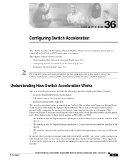
... traffic between modules installed in the chassis. • SE3 handles traffic for Gigabit Ethernet uplink port 1/2 and traffic between SE1 and SE3. The switch acceleration feature reduces internal traffic congestion by creating a full-mesh connection between SE1 and SE3. 78-15486-01 Catalyst 4500 Series, Catalyst 2948G, Catalyst 2980G Switches Software Configuration Guide-Release 8.1 36-1 As...
... traffic between modules installed in the chassis. • SE3 handles traffic for Gigabit Ethernet uplink port 1/2 and traffic between SE1 and SE3. The switch acceleration feature reduces internal traffic congestion by creating a full-mesh connection between SE1 and SE3. 78-15486-01 Catalyst 4500 Series, Catalyst 2948G, Catalyst 2980G Switches Software Configuration Guide-Release 8.1 36-1 As...

