
Hardware Maintenance Manual
Page 3
...this manual is subject to any installation, handling, maintenance, or operating instructions supplied by Cisco and Bringing the power of an uplift, or (7) has been misapplied. BY USING THE SOFTWARE OF CISCO SYSTEMS, INC. IF YOU DO NOT AGREE WITH THE TERMS OF THIS ...SUPPLIERS FROM TIME TO TIME, YOU AGREE TO BE BOUND BY THE TERMS AND CONDITIONS OF THIS LICENSE. Access Without Compromise, Catalyst, CD-PAC, CiscoFusion, Cisco IOS, CiscoView, CiscoWorks, EtherChannel, IGRP, LAN2LAN, LAN2LAN Enterprise, LAN2LAN Remote Office, LAN2PC, LightStream, Newport Systems Solutions, Packet...
...this manual is subject to any installation, handling, maintenance, or operating instructions supplied by Cisco and Bringing the power of an uplift, or (7) has been misapplied. BY USING THE SOFTWARE OF CISCO SYSTEMS, INC. IF YOU DO NOT AGREE WITH THE TERMS OF THIS ...SUPPLIERS FROM TIME TO TIME, YOU AGREE TO BE BOUND BY THE TERMS AND CONDITIONS OF THIS LICENSE. Access Without Compromise, Catalyst, CD-PAC, CiscoFusion, Cisco IOS, CiscoView, CiscoWorks, EtherChannel, IGRP, LAN2LAN, LAN2LAN Enterprise, LAN2LAN Remote Office, LAN2PC, LightStream, Newport Systems Solutions, Packet...

Hardware Maintenance Manual
Page 6
... Connections 3-11 Making T1 Connections 3-14 Making E1 Connections 3-16 Making ATM Connections 3-17 Connecting Routers with a DC-Input Power Supply 3-19 Wiring the DC-Input Power Supply 3-20 Making Final Connections to the Router 3-22 Chapter 4 Troubleshooting the Initial Hardware Configuration 4-1 Problem Solving 4-1 Troubleshooting the... Memory SIMMS 5-9 Installing Main Memory SIMMs 5-11 Replacing Shared-Memory SIMMs 5-13 Inserting Shared-Memory SIMMs 5-14 Removing the Cisco 4500-M and Cisco 4700 Boot Helper Flash Memory SIMM 5-16 Installing Flash-Memory SIMMs 5-17 Replacing Boot ROMs in the...
... Connections 3-11 Making T1 Connections 3-14 Making E1 Connections 3-16 Making ATM Connections 3-17 Connecting Routers with a DC-Input Power Supply 3-19 Wiring the DC-Input Power Supply 3-20 Making Final Connections to the Router 3-22 Chapter 4 Troubleshooting the Initial Hardware Configuration 4-1 Problem Solving 4-1 Troubleshooting the... Memory SIMMS 5-9 Installing Main Memory SIMMs 5-11 Replacing Shared-Memory SIMMs 5-13 Inserting Shared-Memory SIMMs 5-14 Removing the Cisco 4500-M and Cisco 4700 Boot Helper Flash Memory SIMM 5-16 Installing Flash-Memory SIMMs 5-17 Replacing Boot ROMs in the...

Hardware Maintenance Manual
Page 10
...Connections 3-12 Making Single-Attachment Multimode FDDI Connections 3-12 Single-Mode Dual-Attachment FDDI Connections 3-13 Cisco 4000 Series DC-Input Power Supply-Rear View 3-20 Cisco 4000 Series AC-Input Power Supply-Rear View 3-20 DC-Input Power Supply Connections 3-21 Cisco 4000 Series-Front Panel Indicators 4-3 Dual-Port Ethernet Network Processor Module LEDs 4-4 Single-Port Ethernet... V2 4-7 Dual Serial Network Processor Module-Top View 4-8 Dual Serial Port LED Card-Side View 4-8 Dual-Attachment Single-Mode FDDI Module-End View 4-9 x Cisco 4000 Series Hardware Installation and Maintenance
...Connections 3-12 Making Single-Attachment Multimode FDDI Connections 3-12 Single-Mode Dual-Attachment FDDI Connections 3-13 Cisco 4000 Series DC-Input Power Supply-Rear View 3-20 Cisco 4000 Series AC-Input Power Supply-Rear View 3-20 DC-Input Power Supply Connections 3-21 Cisco 4000 Series-Front Panel Indicators 4-3 Dual-Port Ethernet Network Processor Module LEDs 4-4 Single-Port Ethernet... V2 4-7 Dual Serial Network Processor Module-Top View 4-8 Dual Serial Port LED Card-Side View 4-8 Dual-Attachment Single-Mode FDDI Module-End View 4-9 x Cisco 4000 Series Hardware Installation and Maintenance

Hardware Maintenance Manual
Page 15
To order UniverCD, contact your warranty package. Document Organization The major sections of this publication to Ordering Cisco Documentation, which is updated and shipped monthly, so it may be familiar with a DC-input power supply. About This Manual xv UniverCD is included in your local sales representative or call Customer Service. Audience This publication...
To order UniverCD, contact your warranty package. Document Organization The major sections of this publication to Ordering Cisco Documentation, which is updated and shipped monthly, so it may be familiar with a DC-input power supply. About This Manual xv UniverCD is included in your local sales representative or call Customer Service. Audience This publication...
Hardware Maintenance Manual
Page 24
... help . - Turn off switch in the room in which you can weld the metal object to shut the power off (O) and unplug power cords before doing the following ...Fasten your eyes. • Do not perform any action that power is connected to the system. - then take appropriate action. 2-2 Cisco 4000 Series Hardware Installation and Maintenance Then, if an electrical accident ... and after installation. • Always turn off the power and unplug the power cord. • Disconnect all power supplies off . • Before working on equipment that could get medical aid...
... help . - Turn off switch in the room in which you can weld the metal object to shut the power off (O) and unplug power cords before doing the following ...Fasten your eyes. • Do not perform any action that power is connected to the system. - then take appropriate action. 2-2 Cisco 4000 Series Hardware Installation and Maintenance Then, if an electrical accident ... and after installation. • Always turn off the power and unplug the power cord. • Disconnect all power supplies off . • Before working on equipment that could get medical aid...

Hardware Maintenance Manual
Page 26
... the baffles depends on slides, check the position of the router power supply: • Autoranging power supply (200W, 85 to 264 VAC or 40 to 72 VDC, 50 to acceptable operating temperatures without adequate circulation. Power Supply Features Following are secure. If the chassis is installed on the ... air from one chassis can help you are receiving "clean" power (free of the equipment above. • Baffles can be adequate to cool equipment to 60 Hz) • 6-foot electrical power cord 2-4 Cisco 4000 Series Hardware Installation and Maintenance Ambient air temperature might not ...
... the baffles depends on slides, check the position of the router power supply: • Autoranging power supply (200W, 85 to 264 VAC or 40 to 72 VDC, 50 to acceptable operating temperatures without adequate circulation. Power Supply Features Following are secure. If the chassis is installed on the ... air from one chassis can help you are receiving "clean" power (free of the equipment above. • Baffles can be adequate to cool equipment to 60 Hz) • 6-foot electrical power cord 2-4 Cisco 4000 Series Hardware Installation and Maintenance Ambient air temperature might not ...

Hardware Maintenance Manual
Page 29
...assigns unit number addresses to these network modules by starting with zero for Installation 2-7 Network processor module location is the module closest to the power supply. (See Figure 2-2.) For example, the unit number addresses for the FDDI module if one is present. Table 2-1 Slot No. 1...Figure 2-2 are as listed in Table 2-1. Preparing to Make Connections Preparing to Make Connections When viewed from the rear, the power cable and power switch appear on how to remove and replace network processor modules, see the sections "Removing Network Processor Modules" and "Replacing Network...
...assigns unit number addresses to these network modules by starting with zero for Installation 2-7 Network processor module location is the module closest to the power supply. (See Figure 2-2.) For example, the unit number addresses for the FDDI module if one is present. Table 2-1 Slot No. 1...Figure 2-2 are as listed in Table 2-1. Preparing to Make Connections Preparing to Make Connections When viewed from the rear, the power cable and power switch appear on how to remove and replace network processor modules, see the sections "Removing Network Processor Modules" and "Replacing Network...
Hardware Maintenance Manual
Page 59
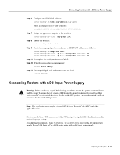
... and Wall-Mount Procedures Overview • Making Console Port Connections • Making Network Connections • Connecting Routers with a DC-Input Power Supply • Making Final Connections to the Router The router ships with thumbscrews. If your system. CHAPTER 3 Installing the Router This chapter ...panel and component tray from the chassis shell and then installing the empty shell in position before making the network and power connections while following the procedures described in the same rack. Sections of instructions for proper ventilation. The console port ...
... and Wall-Mount Procedures Overview • Making Console Port Connections • Making Network Connections • Connecting Routers with a DC-Input Power Supply • Making Final Connections to the Router The router ships with thumbscrews. If your system. CHAPTER 3 Installing the Router This chapter ...panel and component tray from the chassis shell and then installing the empty shell in position before making the network and power connections while following the procedures described in the same rack. Sections of instructions for proper ventilation. The console port ...

Hardware Maintenance Manual
Page 60
Step 2 If you can specify padding for output characters with a console cable. Note Flow control is the module closest to the power supply. (See the sections "Slot Numbering" and "Unit Numbering" in the chapter "Preparing for Installation.") Making Token Ring Connections Step 1... Network Connections Make the network connections by attaching the network interface cables to the appropriate connector on specifying padding, refer to the appropriate Cisco IOS publication. Making Network Connections Follow these steps to connect your system's console port to a terminal: Step 1 Ensure that your ...
Step 2 If you can specify padding for output characters with a console cable. Note Flow control is the module closest to the power supply. (See the sections "Slot Numbering" and "Unit Numbering" in the chapter "Preparing for Installation.") Making Token Ring Connections Step 1... Network Connections Make the network connections by attaching the network interface cables to the appropriate connector on specifying padding, refer to the appropriate Cisco IOS publication. Making Network Connections Follow these steps to connect your system's console port to a terminal: Step 1 Ensure that your ...
Hardware Maintenance Manual
Page 69
... Data Interface (FDDI) connections. If you have any doubt as to how to safely install the Cisco Systems BRI module correctly within the rating of the host chassis power supply. Dual-Attachment FDDI Connections Connect a dual-attachment FDDI module as follows: • +5 VDC/2.5 mA...or Basic Access ISDN (where applicable) before removing any auxiliary apparatus, lies within a host chassis, seek advice from the power supply before removing any telecommunication terminal equipment type approval(s). Ensure that attachments at the interconnection ports of the apparatus are also SELV ...
... Data Interface (FDDI) connections. If you have any doubt as to how to safely install the Cisco Systems BRI module correctly within the rating of the host chassis power supply. Dual-Attachment FDDI Connections Connect a dual-attachment FDDI module as follows: • +5 VDC/2.5 mA...or Basic Access ISDN (where applicable) before removing any auxiliary apparatus, lies within a host chassis, seek advice from the power supply before removing any telecommunication terminal equipment type approval(s). Ensure that attachments at the interconnection ports of the apparatus are also SELV ...
Hardware Maintenance Manual
Page 77
...of the following procedures, ensure that power is OFF, locate the circuit breaker on the panel board that all power is removed from the DC circuit. If you ordered a Cisco 4000 series router with a DC-input power supply; To ensure that services the DC circuit, switch the circuit breaker to the OFF ...position, and tape the switch handle of the circuit breaker in this...
...of the following procedures, ensure that power is OFF, locate the circuit breaker on the panel board that all power is removed from the DC circuit. If you ordered a Cisco 4000 series router with a DC-input power supply; To ensure that services the DC circuit, switch the circuit breaker to the OFF ...position, and tape the switch handle of the circuit breaker in this...
Hardware Maintenance Manual
Page 78
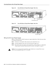
... and Maintenance H2274 H2273 Connecting Routers with a DC-Input Power Supply Figure 3-13 Cisco 4000 Series DC-Input Power Supply-Rear View DC power supply Terminal block cover Figure 3-14 Cisco 4000 Series AC-Input Power Supply-Rear View AC power supply Wiring the DC-Input Power Supply Figure 3-15 shows the Cisco 4000 DC-input power supply terminal block. Step 2 Attach the appropriate lugs at the...
... and Maintenance H2274 H2273 Connecting Routers with a DC-Input Power Supply Figure 3-13 Cisco 4000 Series DC-Input Power Supply-Rear View DC power supply Terminal block cover Figure 3-14 Cisco 4000 Series AC-Input Power Supply-Rear View AC power supply Wiring the DC-Input Power Supply Figure 3-15 shows the Cisco 4000 DC-input power supply terminal block. Step 2 Attach the appropriate lugs at the...
Hardware Maintenance Manual
Page 79
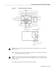
...Remove the tape from the circuit breaker switch handle and restore power by moving the circuit breaker handle to the manufacturer (for wiring the DC-input power supply. This completes the procedure for example, if a failure occurs), remove the power supply terminal block cover so that it ... container. Installing the Router 3-21 Caution To avoid damaging the power supply when returning the chassis to the ON position. Connecting Routers with a DC-Input Power Supply Figure 3-15 DC-Input Power Supply Connections Negative Ground Terminal block cover Terminal block Positive On/Off ...
...Remove the tape from the circuit breaker switch handle and restore power by moving the circuit breaker handle to the manufacturer (for wiring the DC-input power supply. This completes the procedure for example, if a failure occurs), remove the power supply terminal block cover so that it ... container. Installing the Router 3-21 Caution To avoid damaging the power supply when returning the chassis to the ON position. Connecting Routers with a DC-Input Power Supply Figure 3-15 DC-Input Power Supply Connections Negative Ground Terminal block cover Terminal block Positive On/Off ...

Hardware Maintenance Manual
Page 80
... power switch. For routers with the configuration command. Follow this procedure to make the final connections to 60 Hz). This ensures both your safety and adequate cooling. Your configuration can be designated with either the setup command facility or with DC power input, wire the power supply ...as shown in Figure 3-15. For more information on the right side of the front panel (see Figure 1-1) goes ON after a few seconds delay. Making Final Connections to the Router Making Final Connections to the appropriate software publications. 3-22 Cisco...
... power switch. For routers with the configuration command. Follow this procedure to make the final connections to 60 Hz). This ensures both your safety and adequate cooling. Your configuration can be designated with either the setup command facility or with DC power input, wire the power supply ...as shown in Figure 3-15. For more information on the right side of the front panel (see Figure 1-1) goes ON after a few seconds delay. Making Final Connections to the Router Making Final Connections to the appropriate software publications. 3-22 Cisco...
Hardware Maintenance Manual
Page 82
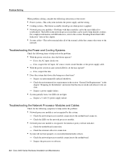
If no , suspect the AC input, AC source, router circuit breaker, or the power supply cable. • With the power switch on when power is recognized, but LEDs do the fans operate? - Check the environmental site requirements in the section "General Site...by the system. - Suspect an environmentally induced shutdown. - Suspect a power supply failure. • System partially boots, but interface port(s) will not boot properly or constantly/intermittently reboots. - Suspect the processor or software. 4-2 Cisco 4000 Series Hardware Installation and Maintenance If no , suspect the fans. ...
If no , suspect the AC input, AC source, router circuit breaker, or the power supply cable. • With the power switch on when power is recognized, but LEDs do the fans operate? - Check the environmental site requirements in the section "General Site...by the system. - Suspect an environmentally induced shutdown. - Suspect a power supply failure. • System partially boots, but interface port(s) will not boot properly or constantly/intermittently reboots. - Suspect the processor or software. 4-2 Cisco 4000 Series Hardware Installation and Maintenance If no , suspect the fans. ...
Hardware Maintenance Manual
Page 96
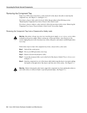
... the handle on your work surface or with a safety latch tab, follow the procedure in or near the power supply, so use extreme caution when working near the power supply. If you have a chassis without a safety latch tab, follow the procedure in the following section "Removing the... the chassis, labeled Chassis release screw in this chapter. Step 1 Turn off power to the system, unplug the power cord, disconnect any of these steps to prevent personal injury. (See Figure 5-1.) 5-2 Cisco 4000 Series Hardware Installation and Maintenance Removing the Component Tray from a chassis with ...
... the handle on your work surface or with a safety latch tab, follow the procedure in or near the power supply, so use extreme caution when working near the power supply. If you have a chassis without a safety latch tab, follow the procedure in the following section "Removing the... the chassis, labeled Chassis release screw in this chapter. Step 1 Turn off power to the system, unplug the power cord, disconnect any of these steps to prevent personal injury. (See Figure 5-1.) 5-2 Cisco 4000 Series Hardware Installation and Maintenance Removing the Component Tray from a chassis with ...
Hardware Maintenance Manual
Page 97
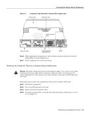
... without a safety latch. Removing the Component Tray from a chassis without a Safety Latch Warning Hazardous voltages may exist in or near the power supply, so use extreme caution when working near the power supply. Step 4 Loosen the (nonremovable) screw in the back of chassis Hand supporting component tray Handle Step 6 While supporting the component tray...
... without a safety latch. Removing the Component Tray from a chassis without a Safety Latch Warning Hazardous voltages may exist in or near the power supply, so use extreme caution when working near the power supply. Step 4 Loosen the (nonremovable) screw in the back of chassis Hand supporting component tray Handle Step 6 While supporting the component tray...

Hardware Maintenance Manual
Page 133
Connection of NET1 and NET2. The Cisco 4000 router is made. Operating Conditions for the United Kingdom E-1 apparatus connected to these ports should be obtained from a supply providing 220-240 VAC, 50/60 Hz up to 5 Amps. See instructions for use when supplied with BS6301: 1989. The Gateway Server... isolation sufficient to satisfy the requirement of BS6301; APPENDIX E Operating Conditions for the United Kingdom For United Kingdom Use Only Cisco Systems declaration of operating conditions: The Cisco 4000 series router is designed to meet the requirements of Power Supply.
Connection of NET1 and NET2. The Cisco 4000 router is made. Operating Conditions for the United Kingdom E-1 apparatus connected to these ports should be obtained from a supply providing 220-240 VAC, 50/60 Hz up to 5 Amps. See instructions for use when supplied with BS6301: 1989. The Gateway Server... isolation sufficient to satisfy the requirement of BS6301; APPENDIX E Operating Conditions for the United Kingdom For United Kingdom Use Only Cisco Systems declaration of operating conditions: The Cisco 4000 series router is designed to meet the requirements of Power Supply.

Hardware Maintenance Manual
Page 141
...C-3 o/r command (reset) C-3 opening the chassis 5-1 operating conditions European Community F-1 temperature 1-3 operating conditions United Kingdom E-1 optical bypass switch connecting to 3-13 uses 2-28 ordering publications xv overview, series 1-1 P packing list 2-36 pinouts auxiliary port A-2 BRI 3-8, A-22...port A-14 four-port A-15 polarity, Ethernet LED 4-5 port locations 2-7 software configuration, serial 4-8 power LED indication 3-22 light 4-3 specifications 1-3 supply features 2-4 system, troubleshooting 4-2 preparing for installation 2-1 to make connections 2-7 preventing ESD damage 2-3...
...C-3 o/r command (reset) C-3 opening the chassis 5-1 operating conditions European Community F-1 temperature 1-3 operating conditions United Kingdom E-1 optical bypass switch connecting to 3-13 uses 2-28 ordering publications xv overview, series 1-1 P packing list 2-36 pinouts auxiliary port A-2 BRI 3-8, A-22...port A-14 four-port A-15 polarity, Ethernet LED 4-5 port locations 2-7 software configuration, serial 4-8 power LED indication 3-22 light 4-3 specifications 1-3 supply features 2-4 system, troubleshooting 4-2 preparing for installation 2-1 to make connections 2-7 preventing ESD damage 2-3...

