
Hardware Maintenance Manual
Page 6
...Making FDDI Network Connections 3-11 Making T1 Connections 3-14 Making E1 Connections 3-16 Making ATM Connections 3-17 Connecting Routers with a DC-Input Power Supply 3-19 Wiring the DC-Input Power Supply 3-20 Making Final Connections to the Router 3-22 Chapter 4 Troubleshooting the Initial Hardware Configuration 4-1 Problem Solving ...Main Memory SIMMS 5-9 Installing Main Memory SIMMs 5-11 Replacing Shared-Memory SIMMs 5-13 Inserting Shared-Memory SIMMs 5-14 Removing the Cisco 4500-M and Cisco 4700 Boot Helper Flash Memory SIMM 5-16 Installing Flash-Memory SIMMs 5-17 Replacing Boot ROMs in the...
...Making FDDI Network Connections 3-11 Making T1 Connections 3-14 Making E1 Connections 3-16 Making ATM Connections 3-17 Connecting Routers with a DC-Input Power Supply 3-19 Wiring the DC-Input Power Supply 3-20 Making Final Connections to the Router 3-22 Chapter 4 Troubleshooting the Initial Hardware Configuration 4-1 Problem Solving ...Main Memory SIMMS 5-9 Installing Main Memory SIMMs 5-11 Replacing Shared-Memory SIMMs 5-13 Inserting Shared-Memory SIMMs 5-14 Removing the Cisco 4500-M and Cisco 4700 Boot Helper Flash Memory SIMM 5-16 Installing Flash-Memory SIMMs 5-17 Replacing Boot ROMs in the...

Hardware Maintenance Manual
Page 10
... Making Single-Attachment Multimode FDDI Connections 3-12 Single-Mode Dual-Attachment FDDI Connections 3-13 Cisco 4000 Series DC-Input Power Supply-Rear View 3-20 Cisco 4000 Series AC-Input Power Supply-Rear View 3-20 DC-Input Power Supply Connections 3-21 Cisco 4000 Series-Front Panel Indicators 4-3 Dual-Port Ethernet Network Processor Module LEDs 4-4 Single-Port... Port Labeled V2 4-7 Dual Serial Network Processor Module-Top View 4-8 Dual Serial Port LED Card-Side View 4-8 Dual-Attachment Single-Mode FDDI Module-End View 4-9 x Cisco 4000 Series Hardware Installation and Maintenance
... Making Single-Attachment Multimode FDDI Connections 3-12 Single-Mode Dual-Attachment FDDI Connections 3-13 Cisco 4000 Series DC-Input Power Supply-Rear View 3-20 Cisco 4000 Series AC-Input Power Supply-Rear View 3-20 DC-Input Power Supply Connections 3-21 Cisco 4000 Series-Front Panel Indicators 4-3 Dual-Port Ethernet Network Processor Module LEDs 4-4 Single-Port... Port Labeled V2 4-7 Dual Serial Network Processor Module-Top View 4-8 Dual Serial Port LED Card-Side View 4-8 Dual-Attachment Single-Mode FDDI Module-End View 4-9 x Cisco 4000 Series Hardware Installation and Maintenance

Hardware Maintenance Manual
Page 15
..., organization, and conventions of product information, or printed publications, refer to Ordering Cisco Documentation, which is included in your local sales representative or call Customer Service. UniverCD is updated and shipped monthly, so it may be familiar with a DC-input power supply. Document Objectives This publication contains the initial site preparation, installation...
..., organization, and conventions of product information, or printed publications, refer to Ordering Cisco Documentation, which is included in your local sales representative or call Customer Service. UniverCD is updated and shipped monthly, so it may be familiar with a DC-input power supply. Document Objectives This publication contains the initial site preparation, installation...

Hardware Maintenance Manual
Page 21
... G.703, Channelized T1/PRI, Channelized T1/PRI, ATM EIA/TIA-2322, EIA/TIA-4491, V.35, X.21, NRZ/NRZI, DTE/DCE; AWG-American Wire Gauge 2. Table 1-1 Cisco 4000 Series Physical Specifications Description Design Specification Dimensions (W x D x H) 17.6" x 17.7" x 3.4" (44.7 cm x 45 cm x 8.6 cm) Weight 24 lb (10....9 kg) (including the chassis and network processor modules) Power Wire Gauge for DC-Input Power Connections 200W, 85 to 264 VAC, 50 to 60 Hz, or 40 to 16 MB 1. ROM-Read-only memory. The Orion microprocessor is...
... G.703, Channelized T1/PRI, Channelized T1/PRI, ATM EIA/TIA-2322, EIA/TIA-4491, V.35, X.21, NRZ/NRZI, DTE/DCE; AWG-American Wire Gauge 2. Table 1-1 Cisco 4000 Series Physical Specifications Description Design Specification Dimensions (W x D x H) 17.6" x 17.7" x 3.4" (44.7 cm x 45 cm x 8.6 cm) Weight 24 lb (10....9 kg) (including the chassis and network processor modules) Power Wire Gauge for DC-Input Power Connections 200W, 85 to 264 VAC, 50 to 60 Hz, or 40 to 16 MB 1. ROM-Read-only memory. The Orion microprocessor is...

Hardware Maintenance Manual
Page 54
...see G.703 / Section 6.3 (CCITT specification) • Input port specifications: see Figure 2-35) controls this function. This provides direct current (DC) isolation between the transmit or receive shield and chassis ground, and the cable resistance (120-ohm or 75-ohm). By default, the CE1..., as a serial interface that supports ISDN PRI. LOOPBACK LOCAL ALARM REMOTE ALARM H3154 Network Connection Considerations Channelized E1 Connections The Cisco 4000 series router supports a channelized E1 (CE1) network processor module with capacitive coupling between the receive (Rx) shield and chassis...
...see G.703 / Section 6.3 (CCITT specification) • Input port specifications: see Figure 2-35) controls this function. This provides direct current (DC) isolation between the transmit or receive shield and chassis ground, and the cable resistance (120-ohm or 75-ohm). By default, the CE1..., as a serial interface that supports ISDN PRI. LOOPBACK LOCAL ALARM REMOTE ALARM H3154 Network Connection Considerations Channelized E1 Connections The Cisco 4000 series router supports a channelized E1 (CE1) network processor module with capacitive coupling between the receive (Rx) shield and chassis...
Hardware Maintenance Manual
Page 59
... you must perform to rack-mount or wall-mount the router, do not install the rubber feet if the chassis is to accommodate cables with a DC-Input Power Supply • Making Final Connections to provide adequate spacing between an ASCII terminal and the system console port, and you must connect an...
... you must perform to rack-mount or wall-mount the router, do not install the rubber feet if the chassis is to accommodate cables with a DC-Input Power Supply • Making Final Connections to provide adequate spacing between an ASCII terminal and the system console port, and you must connect an...
Hardware Maintenance Manual
Page 77
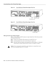
... other applicable codes. Installing the Router 3-19 For identification purposes, Figure 3-13 shows a Cisco 4000 series router with an AC-input power supply. Figure 3-14 shows a Cisco 4000 series router with a DC-input power supply; To ensure that all power is OFF, locate the circuit breaker on ...-if)# no shut Step 9 Create the mapping of protocol addresses to the OFF position, and tape the switch handle of the following procedures, ensure that services the DC circuit, switch the circuit breaker to ATM NSAP addresses, as follows: Router(config-if)# map-list list2 Router(config-map...
... other applicable codes. Installing the Router 3-19 For identification purposes, Figure 3-13 shows a Cisco 4000 series router with an AC-input power supply. Figure 3-14 shows a Cisco 4000 series router with a DC-input power supply; To ensure that all power is OFF, locate the circuit breaker on ...-if)# no shut Step 9 Create the mapping of protocol addresses to the OFF position, and tape the switch handle of the following procedures, ensure that services the DC circuit, switch the circuit breaker to ATM NSAP addresses, as follows: Router(config-if)# map-list list2 Router(config-map...
Hardware Maintenance Manual
Page 78
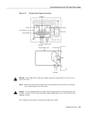
...captive thumbscrew or terminal block contact screws. H2274 H2273 Connecting Routers with a DC-Input Power Supply Figure 3-13 Cisco 4000 Series DC-Input Power Supply-Rear View DC power supply Terminal block cover Figure 3-14 Cisco 4000 Series AC-Input Power Supply-Rear View AC power supply Wiring the... DC-Input Power Supply Figure 3-15 shows the Cisco 4000 DC-input power supply terminal block. The...
...captive thumbscrew or terminal block contact screws. H2274 H2273 Connecting Routers with a DC-Input Power Supply Figure 3-13 Cisco 4000 Series DC-Input Power Supply-Rear View DC power supply Terminal block cover Figure 3-14 Cisco 4000 Series AC-Input Power Supply-Rear View AC power supply Wiring the... DC-Input Power Supply Figure 3-15 shows the Cisco 4000 DC-input power supply terminal block. The...
Hardware Maintenance Manual
Page 79
... Ground Terminal block cover Terminal block Positive On/Off Captive screw Grommet Terminal block cover Terminal block H2275 Grommet Warning After wiring the DC-input power supply, replace the terminal block cover and screw to the ON position. This completes the procedure for example, if a...To avoid damaging the power supply when returning the chassis to the manufacturer (for wiring the DC-input power supply. Installing the Router 3-21 Step 4 Remove the tape from the circuit breaker switch handle and restore power by moving the circuit breaker handle to ensure user safety.
... Ground Terminal block cover Terminal block Positive On/Off Captive screw Grommet Terminal block cover Terminal block H2275 Grommet Warning After wiring the DC-input power supply, replace the terminal block cover and screw to the ON position. This completes the procedure for example, if a...To avoid damaging the power supply when returning the chassis to the manufacturer (for wiring the DC-input power supply. Installing the Router 3-21 Step 4 Remove the tape from the circuit breaker switch handle and restore power by moving the circuit breaker handle to ensure user safety.

Hardware Maintenance Manual
Page 80
...panel (see Figure 1-1) goes ON after a few seconds delay. Step 2 Turn ON the system power switch. For routers with AC power input, plug the system power cord into a 3-terminal, single-phase ...the acceptable range (200W, 85 to 264 VAC, 50 to the router: Step 1 For routers with DC power input, wire the power supply as shown in Figure 3-15. This ensures both your safety and... to the Router Making Final Connections to the appropriate software publications. 3-22 Cisco 4000 Series Hardware Installation and Maintenance Your configuration can be designated with either the setup command ...
...panel (see Figure 1-1) goes ON after a few seconds delay. Step 2 Turn ON the system power switch. For routers with AC power input, plug the system power cord into a 3-terminal, single-phase ...the acceptable range (200W, 85 to 264 VAC, 50 to the router: Step 1 For routers with DC power input, wire the power supply as shown in Figure 3-15. This ensures both your safety and... to the Router Making Final Connections to the appropriate software publications. 3-22 Cisco 4000 Series Hardware Installation and Maintenance Your configuration can be designated with either the setup command ...