
Hardware Installation Guide
Page 12
Contents E A P P E N D I X INDEX Translated Safety Warnings E-1 Attaching the Cisco RPS (model PWR300-AC-RPS-N1) E-1 Attaching the Cisco RPS (model PWR675-AC-RPS-N1) E-2 Installation Warning E-4 Installation Instructions E-5 Jewelry Removal Warning E-6 Stacking the Chassis ...12 Overtemperature Warning E-14 Working During Lightning Activity E-16 Product Disposal Warning E-17 Chassis Warning for Rack-Mounting and Servicing E-19 Redundant Power Supply Connection Warning E-24 Switch Installation Warning E-25 Restricted Area E-27 Ethernet Cable Shielding in Offices E-28 Laser Beam Exposure E-30 ...
Contents E A P P E N D I X INDEX Translated Safety Warnings E-1 Attaching the Cisco RPS (model PWR300-AC-RPS-N1) E-1 Attaching the Cisco RPS (model PWR675-AC-RPS-N1) E-2 Installation Warning E-4 Installation Instructions E-5 Jewelry Removal Warning E-6 Stacking the Chassis ...12 Overtemperature Warning E-14 Working During Lightning Activity E-16 Product Disposal Warning E-17 Chassis Warning for Rack-Mounting and Servicing E-19 Redundant Power Supply Connection Warning E-24 Switch Installation Warning E-25 Restricted Area E-27 Ethernet Cable Shielding in Offices E-28 Laser Beam Exposure E-30 ...

Hardware Installation Guide
Page 42
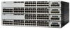
...switches. Catalyst 3750G-24TS-24 10/100/1000 Ethernet ports and 4 SFP module slots - For 10/100 ports, autonegotiates the speed and duplex settings - Connection for optional Cisco RPS 300 redundant power system that operates on AC input and supplies backup DC power output to nine ...Switches are the switch features: • Hardware - Catalyst 3750 Switch Hardware Installation Guide 2-2 78-15136-02 Catalyst 3750G-24T-24 10/100/1000 Ethernet ports - Catalyst 3750-24TS-24 10/100 Ethernet ports and 2 small form-factor pluggable (SFP) module slots - Features Chapter 2 Product Overview ...
...switches. Catalyst 3750G-24TS-24 10/100/1000 Ethernet ports and 4 SFP module slots - For 10/100 ports, autonegotiates the speed and duplex settings - Connection for optional Cisco RPS 300 redundant power system that operates on AC input and supplies backup DC power output to nine ...Switches are the switch features: • Hardware - Catalyst 3750 Switch Hardware Installation Guide 2-2 78-15136-02 Catalyst 3750G-24T-24 10/100/1000 Ethernet ports - Catalyst 3750-24TS-24 10/100 Ethernet ports and 2 small form-factor pluggable (SFP) module slots - Features Chapter 2 Product Overview ...

Hardware Installation Guide
Page 43
...Catalyst 3750 switches. The ports are numbered 1 through 24. Port 3 is above port 4, and so on AC input and supplies backup DC power output to 28. 78-15136-02 Catalyst 3750 Switch Hardware Installation Guide 2-3 The SFP port numbers are numbered 25 to the ... and 2 (right). Chapter 2 Product Overview Front Panel Description Note The Cisco RPS 300 does not support the Catalyst 3750G-24TS switch. - Connection for optional Cisco RPS 675 redundant power system that operates on . Figure 2-1 Catalyst 3750-24TS Front Panel 86541 SYST RPS MASTR STAT DUPLX SPEED STACK MODE 12 1X...
...Catalyst 3750 switches. The ports are numbered 1 through 24. Port 3 is above port 4, and so on AC input and supplies backup DC power output to 28. 78-15136-02 Catalyst 3750 Switch Hardware Installation Guide 2-3 The SFP port numbers are numbered 25 to the ... and 2 (right). Chapter 2 Product Overview Front Panel Description Note The Cisco RPS 300 does not support the Catalyst 3750G-24TS switch. - Connection for optional Cisco RPS 675 redundant power system that operates on . Figure 2-1 Catalyst 3750-24TS Front Panel 86541 SYST RPS MASTR STAT DUPLX SPEED STACK MODE 12 1X...

Hardware Installation Guide
Page 49
... has failed, and the RPS is off or not properly connected. Contact Cisco Systems. The internal power supply in a fault condition. Table 2-2 RPS LED Color Off Green Flashing green Amber Flashing amber RPS Status RPS is providing power to the switch (redundancy has been allocated to the 10/100 and 10/100/1000 Ports" section...
... has failed, and the RPS is off or not properly connected. Contact Cisco Systems. The internal power supply in a fault condition. Table 2-2 RPS LED Color Off Green Flashing green Amber Flashing amber RPS Status RPS is providing power to the switch (redundancy has been allocated to the 10/100 and 10/100/1000 Ports" section...

Hardware Installation Guide
Page 57
... Description Cisco RPS 675 The RPS is a redundant power system that adapter from Cisco. For more information on the Cisco RPS 300, refer to the Cisco RPS 300 Redundant Power System Hardware Installation Guide. It automatically senses when the internal power supply of a connected device fails and provides power to...provide an RJ-45-to the switch. It automatically senses when the internal power supply of a connected device fails and provides power to the Cisco RPS 675 Redundant Power System Hardware Installation Guide. The Cisco RPS 675 has two output levels: -48V and 12V with a total...
... Description Cisco RPS 675 The RPS is a redundant power system that adapter from Cisco. For more information on the Cisco RPS 300, refer to the Cisco RPS 300 Redundant Power System Hardware Installation Guide. It automatically senses when the internal power supply of a connected device fails and provides power to...provide an RJ-45-to the switch. It automatically senses when the internal power supply of a connected device fails and provides power to the Cisco RPS 675 Redundant Power System Hardware Installation Guide. The Cisco RPS 675 has two output levels: -48V and 12V with a total...

Hardware Installation Guide
Page 68
...redundant power system (RPS) connector cover (for attaching the brackets to a rack - StackWise cable: 0.5-meter, 1-meter, or 3-meter cable. These sections describe the steps required to connect a PC to the switch console port, and to one of the StackWise cable, the 0.5-meter cable is supplied... or Terminal to the Console Port, page 3-8 • Powering On the Switch and Running POST, page 3-10 Connecting ...a PC to the console port, use the supplied RJ-45-to a terminal, you don't ...provide a RJ-45-to the switch (Catalyst 3750-24TS, 3750G-24T, and 3750-48TS switches) - Preparing for wall...
...redundant power system (RPS) connector cover (for attaching the brackets to a rack - StackWise cable: 0.5-meter, 1-meter, or 3-meter cable. These sections describe the steps required to connect a PC to the switch console port, and to one of the StackWise cable, the 0.5-meter cable is supplied... or Terminal to the Console Port, page 3-8 • Powering On the Switch and Running POST, page 3-10 Connecting ...a PC to the console port, use the supplied RJ-45-to a terminal, you don't ...provide a RJ-45-to the switch (Catalyst 3750-24TS, 3750G-24T, and 3750-48TS switches) - Preparing for wall...
Hardware Installation Guide
Page 195
... 3-17 to 3-36 product disposal warning E-17 publications, related xxi Q qualified personnel warning E-4 R rack-mounting 3-18 to 3-36 rear panel clearance 3-6 description 2-14 to 2-17 redundant power supply See RPS regulatory statements, EMC 3-4 removing SFP modules 3-43 to 3-44 78-15136-02 Catalyst 3750 Switch Hardware Installation Guide IN-5
... 3-17 to 3-36 product disposal warning E-17 publications, related xxi Q qualified personnel warning E-4 R rack-mounting 3-18 to 3-36 rear panel clearance 3-6 description 2-14 to 2-17 redundant power supply See RPS regulatory statements, EMC 3-4 removing SFP modules 3-43 to 3-44 78-15136-02 Catalyst 3750 Switch Hardware Installation Guide IN-5


