
Getting Started Guide
Page 3
... 17X 18 19 20 21 22 23 24 25 26 27 28 29 30 31 32 16X 18X 33 31X 33X 34 35 36 37 38 39 40 41 42 43 44 45 46 47 48 47X 32X 34X Catalyst 3750G SERIES 49 51 Catalyst 3750 switch 48X 50 52 0.5-meter, 1.0-meter or 3.0-meter...
... 17X 18 19 20 21 22 23 24 25 26 27 28 29 30 31 32 16X 18X 33 31X 33X 34 35 36 37 38 39 40 41 42 43 44 45 46 47 48 47X 32X 34X Catalyst 3750G SERIES 49 51 Catalyst 3750 switch 48X 50 52 0.5-meter, 1.0-meter or 3.0-meter...

Getting Started Guide
Page 5
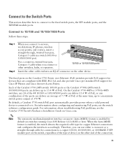
...-enabled PC Step 10 The Express Setup page appears. Step 7 Connect a Category 5 Ethernet cable to the Ethernet port on the switch front panel. If it does not appear, see the "In Case of the cable to any 10/100 or 10/100/1000... 45 67 89 10 11 12 13 14 15 16 17 15X 17X 16X 18X 18 19 20 21 22 23 24 25 26 27 28 29 30 31 32 33 31X 33X 34 35 36 37 38 39 40 41 42 43... 44 45 46 47 48 Catalyst 3560G SERIES PoE-48 47X 32X 34X 49 51 48X 50 52 Step 8 Step 9 Verify that the switch and PC Ethernet ports LEDs are green. Start a web browser on your...
...-enabled PC Step 10 The Express Setup page appears. Step 7 Connect a Category 5 Ethernet cable to the Ethernet port on the switch front panel. If it does not appear, see the "In Case of the cable to any 10/100 or 10/100/1000... 45 67 89 10 11 12 13 14 15 16 17 15X 17X 16X 18X 18 19 20 21 22 23 24 25 26 27 28 29 30 31 32 33 31X 33X 34 35 36 37 38 39 40 41 42 43... 44 45 46 47 48 Catalyst 3560G SERIES PoE-48 47X 32X 34X 49 51 48X 50 52 Step 8 Step 9 Verify that the switch and PC Ethernet ports LEDs are green. Start a web browser on your...
Getting Started Guide
Page 13
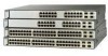
...other Catalyst 3750 switches as radios, power lines, and fluorescent lighting fixtures. • For 10/100 ports and 10/100/1000 ports, the cable length from the AC power outlet to install the switch, verify that these illustrations. Before You Begin When determining where to the connector on Cisco.com....shipped with the module. 13 Front-panel LEDs can reach from a switch to the rear of electrical noise, such as shown in a 24-inch rack or on a wall, and for connecting StackWise cables to rack-mount the switch. Equipment That You Supply You need to supply a number-2 Phillips ...
...other Catalyst 3750 switches as radios, power lines, and fluorescent lighting fixtures. • For 10/100 ports and 10/100/1000 ports, the cable length from the AC power outlet to install the switch, verify that these illustrations. Before You Begin When determining where to the connector on Cisco.com....shipped with the module. 13 Front-panel LEDs can reach from a switch to the rear of electrical noise, such as shown in a 24-inch rack or on a wall, and for connecting StackWise cables to rack-mount the switch. Equipment That You Supply You need to supply a number-2 Phillips ...

Getting Started Guide
Page 16
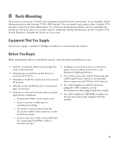
...MODE 1 1X 2X 23 45 67 89 10 11 12 13 14 15 16 15X 17X 17 18 19 20 21 22 23 24 25 26 27 28 29 30 31 32 16X 18X 33 31X 33X 34 35 36 37 38 39 40 41 42 43 44...MODE 1 1X 2X 23 45 67 89 10 11 12 13 14 15 16 15X 17X 17 18 19 20 21 22 23 24 25 26 27 28 29 30 31 32 16X 18X 33 31X 33X 34 35 36 37 38 39 40 41 42 43 ...CONSOLE DSCPIENPCPOIUWFTIEESDRFISONURMPRPAELNYMUOATLE Rear-mounting position 16 Attaching the Brackets Use four Phillips flat-head screws to attach the long side of the brackets to Catalyst 3750 switches in one of three mounting positions.
...MODE 1 1X 2X 23 45 67 89 10 11 12 13 14 15 16 15X 17X 17 18 19 20 21 22 23 24 25 26 27 28 29 30 31 32 16X 18X 33 31X 33X 34 35 36 37 38 39 40 41 42 43 44...MODE 1 1X 2X 23 45 67 89 10 11 12 13 14 15 16 15X 17X 17 18 19 20 21 22 23 24 25 26 27 28 29 30 31 32 16X 18X 33 31X 33X 34 35 36 37 38 39 40 41 42 43 ...CONSOLE DSCPIENPCPOIUWFTIEESDRFISONURMPRPAELNYMUOATLE Rear-mounting position 16 Attaching the Brackets Use four Phillips flat-head screws to attach the long side of the brackets to Catalyst 3750 switches in one of three mounting positions.
Getting Started Guide
Page 17
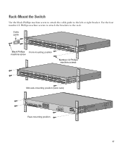
Rack-Mount the Switch Use the black Phillips machine screw to attach the cable guide to the rack. Cable guide SYST RPS MASTR STAT DUPLX SPEED STACK MODE 1 1X 2X 23 45 67 8 9 10 11 12 13 14 15 16 17 15X 17X 18 19 20 21 22 23 24 25 26 27... 28 29 30 31 32 16X 18X 33 31X 33X 34 35 36 37 38 39 40 41 42 43 44 45 46 47 48 47X 32X 34X Catalyst 3750G SERIES 49 51 Black Phillips Front-mounting position...
Rack-Mount the Switch Use the black Phillips machine screw to attach the cable guide to the rack. Cable guide SYST RPS MASTR STAT DUPLX SPEED STACK MODE 1 1X 2X 23 45 67 8 9 10 11 12 13 14 15 16 17 15X 17X 18 19 20 21 22 23 24 25 26 27... 28 29 30 31 32 16X 18X 33 31X 33X 34 35 36 37 38 39 40 41 42 43 44 45 46 47 48 47X 32X 34X Catalyst 3750G SERIES 49 51 Black Phillips Front-mounting position...
Getting Started Guide
Page 19
... configuring and monitoring PoE ports, see the Catalyst 3750 Switch Hardware Installation Guide on the other cable end into an RJ-45 connector on Cisco.com. Each of the Catalyst 3750-24PS switch 10/100 ports or the Catalyst 3750G-24PS switch 10/100/1000 ports can deliver an average..., the switch detects the required cable type for Cisco IP Phones and Cisco Aironet Access Points. Connect to 15.4 W of the connection. 19 For information about troubleshooting PoE problems, see the switch software configuration guide. On the Catalyst 3750-48PS or 3750G-48PS switches, any 24 of the...
... configuring and monitoring PoE ports, see the Catalyst 3750 Switch Hardware Installation Guide on the other cable end into an RJ-45 connector on Cisco.com. Each of the Catalyst 3750-24PS switch 10/100 ports or the Catalyst 3750G-24PS switch 10/100/1000 ports can deliver an average..., the switch detects the required cable type for Cisco IP Phones and Cisco Aironet Access Points. Connect to 15.4 W of the connection. 19 For information about troubleshooting PoE problems, see the switch software configuration guide. On the Catalyst 3750-48PS or 3750G-48PS switches, any 24 of the...
Getting Started Guide
Page 20
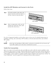
..., the port LED turns amber while the switch establishes a link. This process takes about online assistance. 20 If the LED is absolutely necessary. Insert the other device. 13 14 13X 15 16 17 18 19 20 21 22 23 24 Catalyst 3750G SERIES PoE-24 23X 25 14X 27 24X 26 28 SFP ...the SFP Modules and Connect to the Ports Follow these steps: Step 1 Grasp the module on the sides, and insert it into the switch slot until you connect to SFP modules, see the release notes on Cisco.com. Step 2 Insert an appropriate cable into the other cable end into the module port.
..., the port LED turns amber while the switch establishes a link. This process takes about online assistance. 20 If the LED is absolutely necessary. Insert the other device. 13 14 13X 15 16 17 18 19 20 21 22 23 24 Catalyst 3750G SERIES PoE-24 23X 25 14X 27 24X 26 28 SFP ...the SFP Modules and Connect to the Ports Follow these steps: Step 1 Grasp the module on the sides, and insert it into the switch slot until you connect to SFP modules, see the release notes on Cisco.com. Step 2 Insert an appropriate cable into the other cable end into the module port.
Getting Started Guide
Page 24
... Switch Command Reference • Catalyst 3750, 3560, 2975, 2970, and 2960 Switch System Message Guide 8 Obtaining Documentation, Obtaining Support, and Security Guidelines For information on obtaining documentation, submitting a service request, and gathering additional information, see the product documentation and compliance document that shipped with this product. 24 The RSS feeds are a free service and Cisco...
... Switch Command Reference • Catalyst 3750, 3560, 2975, 2970, and 2960 Switch System Message Guide 8 Obtaining Documentation, Obtaining Support, and Security Guidelines For information on obtaining documentation, submitting a service request, and gathering additional information, see the product documentation and compliance document that shipped with this product. 24 The RSS feeds are a free service and Cisco...

