Getting Started Guide
Page 2
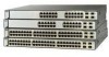
...refer to the documents that are switch management options, basic rack-mounting procedures, stacking procedures, port and module connection procedures, power connection procedures, and troubleshooting help. The software version is missing or damaged, contact your Catalyst switch. Verify that you do not ... for future use Express Setup to initially configure your Cisco representative or reseller for instructions. Some switch models might include additional items that match the Cisco IOS software version running on the switch. For translations of the StackWise cable, the 0.5-meter...
...refer to the documents that are switch management options, basic rack-mounting procedures, stacking procedures, port and module connection procedures, power connection procedures, and troubleshooting help. The software version is missing or damaged, contact your Catalyst switch. Verify that you do not ... for future use Express Setup to initially configure your Cisco representative or reseller for instructions. Some switch models might include additional items that match the Cisco IOS software version running on the switch. For translations of the StackWise cable, the 0.5-meter...

Getting Started Guide
Page 5
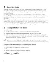
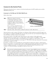
... does not appear, see the "In Case of the cable to any 10/100 or 10/100/1000 Ethernet port on your PC. Step 7 Connect a Category 5 Ethernet cable to the Ethernet port on the switch front panel. Start a web browser on your PC. SYST RPS MASTR STAT DUPLX SPEED STACK MODE 1 1X 2X... 26 27 28 29 30 31 32 33 31X 33X 34 35 36 37 38 39 40 41 42 43 44 45 46 47 48 Catalyst 3560G SERIES PoE-48 47X 32X 34X 49 51 48X 50 52 Step 8 Step 9 Verify that the switch and PC Ethernet ports LEDs are green.
... does not appear, see the "In Case of the cable to any 10/100 or 10/100/1000 Ethernet port on your PC. Step 7 Connect a Category 5 Ethernet cable to the Ethernet port on the switch front panel. Start a web browser on your PC. SYST RPS MASTR STAT DUPLX SPEED STACK MODE 1 1X 2X... 26 27 28 29 30 31 32 33 31X 33X 34 35 36 37 38 39 40 41 42 43 44 45 46 47 48 Catalyst 3560G SERIES PoE-48 47X 32X 34X 49 51 48X 50 52 Step 8 Step 9 Verify that the switch and PC Ethernet ports LEDs are green.
Getting Started Guide
Page 9
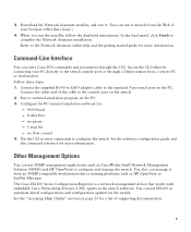
... port or through the CLI. no parity - 1 stop bit - 3. Refer to automate initial configurations and configuration updates on the switch. 2. See the software configuration guide and the command reference for more information. You can enter Cisco IOS commands and parameters through a Telnet ...session from an SNMP-compatible workstation that is a network management device that works with embedded Cisco Networking Services (CNS) agents in the switch software. Download the Network Assistant installer, and run it from a remote PC or workstation. Other Management ...
... port or through the CLI. no parity - 1 stop bit - 3. Refer to automate initial configurations and configuration updates on the switch. 2. See the software configuration guide and the command reference for more information. You can enter Cisco IOS commands and parameters through a Telnet ...session from an SNMP-compatible workstation that is a network management device that works with embedded Cisco Networking Services (CNS) agents in the switch software. Download the Network Assistant installer, and run it from a remote PC or workstation. Other Management ...
Getting Started Guide
Page 13
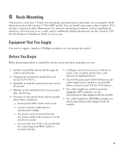
...a wall, and for additional cabling information, see the Catalyst 3750 Switch Hardware Installation Guide on the switch rear panel. - You can install and connect other Catalyst 3750 switches as installing the switch in these conditions: - Access to ports is sufficient for small form-factor pluggable (SFP) modules... switch front and rear panels meets these illustrations. AC power cord can be easily read. - Access to the connector on Cisco.com. Front-panel LEDs can reach from a switch to rack-mount the switch. As an example, all the illustrations show the Catalyst 3750G...
...a wall, and for additional cabling information, see the Catalyst 3750 Switch Hardware Installation Guide on the switch rear panel. - You can install and connect other Catalyst 3750 switches as installing the switch in these conditions: - Access to ports is sufficient for small form-factor pluggable (SFP) modules... switch front and rear panels meets these illustrations. AC power cord can be easily read. - Access to the connector on Cisco.com. Front-panel LEDs can reach from a switch to rack-mount the switch. As an example, all the illustrations show the Catalyst 3750G...
Getting Started Guide
Page 15
Warning If a redundant power system (RPS) is installed, the following ports must be accessed only through an approved network termination unit with integral circuit protection: 10/100/1000 Ethernet. Statement 1072 15 Avoid using uninsulated... of security. Statement 265 Warning Class 1 laser product. Statement 1008 Warning For connections outside the building where the equipment is not connected to the switch, install an RPS connector cover on Power over Ethernet (PoE) circuits if interconnections are made using such interconnection methods, unless the exposed metal parts ...
Warning If a redundant power system (RPS) is installed, the following ports must be accessed only through an approved network termination unit with integral circuit protection: 10/100/1000 Ethernet. Statement 1072 15 Avoid using uninsulated... of security. Statement 265 Warning Class 1 laser product. Statement 1008 Warning For connections outside the building where the equipment is not connected to the switch, install an RPS connector cover on Power over Ethernet (PoE) circuits if interconnections are made using such interconnection methods, unless the exposed metal parts ...
Getting Started Guide
Page 18
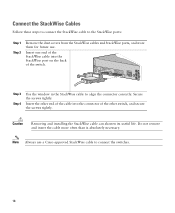
... the back of the other switch, and secure the screws tightly. Connect the StackWise Cables Follow these steps to connect the StackWise cable to the StackWise ports: Step 1 Step 2 Remove the dust covers from the StackWise cables and StackWise ports, and store them for future use a Cisco-approved StackWise cable to align the connector...
... the back of the other switch, and secure the screws tightly. Connect the StackWise Cables Follow these steps to connect the StackWise cable to the StackWise ports: Step 1 Step 2 Remove the dust covers from the StackWise cables and StackWise ports, and store them for future use a Cisco-approved StackWise cable to align the connector...
Getting Started Guide
Page 19
... use either a crossover or a straight-through , twisted four-pair, Category 5 cable in a switch 10/100 or 10/100/1000 port. For information about configuring and monitoring PoE ports, see the Catalyst 3750 Switch Hardware Installation Guide on Cisco.com. The fixed ports on switches running Cisco IOS Release 12.2(18)SE or later. For information about troubleshooting PoE problems...
... use either a crossover or a straight-through , twisted four-pair, Category 5 cable in a switch 10/100 or 10/100/1000 port. For information about configuring and monitoring PoE ports, see the Catalyst 3750 Switch Hardware Installation Guide on Cisco.com. The fixed ports on switches running Cisco IOS Release 12.2(18)SE or later. For information about troubleshooting PoE problems...
Getting Started Guide
Page 20
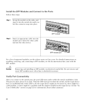
... 27 24X 26 28 SFP module 13 14 13X 15 16 17 18 19 20 21 22 23 24 Catalyst 3750G SERIES PoE-24 23X 25 14X 27 24X 26 28 SFP module port For a list of Difficulty" section on page 22 for information about 30 seconds. See the "In Case of... LED is absolutely necessary. Do not remove and insert SFP modules more often than is off, the target device might not be turned on Cisco.com. Then the LED turns green when the switch and the target device have an established link. For detailed instructions on installing, removing, and connecting to the...
... 27 24X 26 28 SFP module 13 14 13X 15 16 17 18 19 20 21 22 23 24 Catalyst 3750G SERIES PoE-24 23X 25 14X 27 24X 26 28 SFP module port For a list of Difficulty" section on page 22 for information about 30 seconds. See the "In Case of... LED is absolutely necessary. Do not remove and insert SFP modules more often than is off, the target device might not be turned on Cisco.com. Then the LED turns green when the switch and the target device have an established link. For detailed instructions on installing, removing, and connecting to the...
Getting Started Guide
Page 21
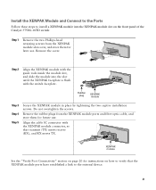
... that transmit (TX) meets receive (RX), and RX meets TX. 1 TX RX Catalyst 3750 series XENPAK module See the "Verify Port Connectivity" section on page 20 for instructions on the front panel of the Catalyst 3750G-16TD switch: Step 1 Remove the two Phillips-head retaining screws from the XENPAK module... ports and fiber-optic cable, and store them for future use . Remove the rubber plugs from the XENPAK module slot ...
... that transmit (TX) meets receive (RX), and RX meets TX. 1 TX RX Catalyst 3750 series XENPAK module See the "Verify Port Connectivity" section on page 20 for instructions on the front panel of the Catalyst 3750G-16TD switch: Step 1 Remove the two Phillips-head retaining screws from the XENPAK module... ports and fiber-optic cable, and store them for future use . Remove the rubber plugs from the XENPAK module slot ...
Getting Started Guide
Page 22
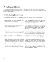
... you connect a crossover cable instead of If yes, connect a straight-through cable to an a straight-through Ethernet cable between a Ethernet port on the switch and the PC. Troubleshooting Express Setup If Express Setup does not run, or if the Express Setup page does not appear in the browser.... • Did you press the Mode button while the switch was in this section and also on Cisco.com. If yes, disconnect the cable from the console port. If yes, wait until POST completes. Power cycle the switch. Confirm that the switch was still running POST? green. (The RPS LED is ...
... you connect a crossover cable instead of If yes, connect a straight-through cable to an a straight-through Ethernet cable between a Ethernet port on the switch and the PC. Troubleshooting Express Setup If Express Setup does not run, or if the Express Setup page does not appear in the browser.... • Did you press the Mode button while the switch was in this section and also on Cisco.com. If yes, disconnect the cable from the console port. If yes, wait until POST completes. Power cycle the switch. Confirm that the switch was still running POST? green. (The RPS LED is ...


