Hardware Installation Guide
Page 6
... and Network Interface Cards 4-5 Cabling Distance 4-5 Resetting the Switch to the Factory Default Settings 4-5 Finding the Switch Serial Number 4-6 Replacing a Failed Data Stack Member (Catalyst 3750-X Switches) 4-6 Technical Specifications A-1 Switch Specifications A-1 Power Supply Module Specifications A-2 Fan Module... Port C-2 USB Console Port C-2 Installing the Cisco Microsoft Windows USB Device Driver C-3 Installing the Cisco Microsoft Windows XP USB Driver C-4 Installing the Cisco Microsoft Windows 2000 USB Driver C-4 Installing the Cisco Microsoft Windows Vista and Windows 7 USB Driver...
... and Network Interface Cards 4-5 Cabling Distance 4-5 Resetting the Switch to the Factory Default Settings 4-5 Finding the Switch Serial Number 4-6 Replacing a Failed Data Stack Member (Catalyst 3750-X Switches) 4-6 Technical Specifications A-1 Switch Specifications A-1 Power Supply Module Specifications A-2 Fan Module... Port C-2 USB Console Port C-2 Installing the Cisco Microsoft Windows USB Device Driver C-3 Installing the Cisco Microsoft Windows XP USB Driver C-4 Installing the Cisco Microsoft Windows 2000 USB Driver C-4 Installing the Cisco Microsoft Windows Vista and Windows 7 USB Driver...

Hardware Installation Guide
Page 17
Table 1-4 Supported Cisco SFP Modules Part Number GLC-GE-100FX=1,2,3 GLC-LH-SM= GLC-SX-MM= GLC-T=1, 3 GLC-ZX-SM= GLC-BX-D=1 GLC-BX-U=1 CWDM-SFP-1470= CWDM-... connections. Note The (downlink) SFP module slots on the switch. Use only Cisco SFP modules on the Catalyst 3750-X-12S and Catalyst 3750-X-24S switch front panel support any combination of standard SFP modules. SFP+ modules are field-replaceable, providing the uplink interfaces when installed in an SFP module slot. The SFP...
Table 1-4 Supported Cisco SFP Modules Part Number GLC-GE-100FX=1,2,3 GLC-LH-SM= GLC-SX-MM= GLC-T=1, 3 GLC-ZX-SM= GLC-BX-D=1 GLC-BX-U=1 CWDM-SFP-1470= CWDM-... connections. Note The (downlink) SFP module slots on the switch. Use only Cisco SFP modules on the Catalyst 3750-X-12S and Catalyst 3750-X-24S switch front panel support any combination of standard SFP modules. SFP+ modules are field-replaceable, providing the uplink interfaces when installed in an SFP module slot. The SFP...
Hardware Installation Guide
Page 31
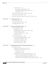
... 12 12 34 56 78 Catalys9 t 10 3750-X 11 12 PoE+48 C3KX-NM-10G NMEOTWDUOLREK G1 G2/TE1 G3 G4/TE2 For information about replacing a power supply module, wiring a DC power supply module, and module specifications, see Chapter 3, "Power Supply and Fan Module Installation," and Appendix A, "... If the fan fails, the LED turns to the switch: XPS 2200. XPS Connector Warning Attach only the following Cisco external power system to amber. Statement 387 The Cisco XPS 2200 is a expandable power system that can support nine network switches and provides power to switch active. The ...
... 12 12 34 56 78 Catalys9 t 10 3750-X 11 12 PoE+48 C3KX-NM-10G NMEOTWDUOLREK G1 G2/TE1 G3 G4/TE2 For information about replacing a power supply module, wiring a DC power supply module, and module specifications, see Chapter 3, "Power Supply and Fan Module Installation," and Appendix A, "... If the fan fails, the LED turns to the switch: XPS 2200. XPS Connector Warning Attach only the following Cisco external power system to amber. Statement 387 The Cisco XPS 2200 is a expandable power system that can support nine network switches and provides power to switch active. The ...

Hardware Installation Guide
Page 36
... can cause serious burns or weld the metal object to the terminals. Statement 1028 Warning Only trained and qualified personnel should be allowed to install, replace, or service this emergency number is 911. Preparing for installation in restricted access areas. Metal objects will heat up when connected to power and ground...
... can cause serious burns or weld the metal object to the terminals. Statement 1028 Warning Only trained and qualified personnel should be allowed to install, replace, or service this emergency number is 911. Preparing for installation in restricted access areas. Metal objects will heat up when connected to power and ground...

Hardware Installation Guide
Page 54
...to the connector on the other switch, and tighten the retainer screws to align the connector correctly. When the connectors are not being used, replace the dust covers. 2-20 Catalyst 3750-X and 3560-X Switch Hardware Installation Guide OL-19593-02 Figure 2-19 Connecting the StackWise Cable in ...screws. When you need to remove the StackWise cable from the StackWise cables and StackWise ports, and store them for future use a Cisco-approved StackWise cable to the StackWise port on page 2-4. Always use . Connect it to connect the switches. Connecting to the StackWise Ports...
...to the connector on the other switch, and tighten the retainer screws to align the connector correctly. When the connectors are not being used, replace the dust covers. 2-20 Catalyst 3750-X and 3560-X Switch Hardware Installation Guide OL-19593-02 Figure 2-19 Connecting the StackWise Cable in ...screws. When you need to remove the StackWise cable from the StackWise cables and StackWise ports, and store them for future use a Cisco-approved StackWise cable to the StackWise port on page 2-4. Always use . Connect it to connect the switches. Connecting to the StackWise Ports...

Hardware Installation Guide
Page 56
...a green stripe into an XPS port on page 2-8. Do not remove and insert the cable more often than necessary. If you remove a module, replace it with a red or yellow stripe to an XPS 2200 power supply. (Figure 2-21) Hand-tighten the captive screws to secure the StackPower connectors...in the network module slot. Figure 2-21 Connecting the StackPower Cable to install and remove network modules or the blank module. Always use a Cisco-approved StackPower cable to connect the switches. Align the connector correctly, and insert the end of the cable with another network module. 2-22 ...
...a green stripe into an XPS port on page 2-8. Do not remove and insert the cable more often than necessary. If you remove a module, replace it with a red or yellow stripe to an XPS 2200 power supply. (Figure 2-21) Hand-tighten the captive screws to secure the StackPower connectors...in the network module slot. Figure 2-21 Connecting the StackPower Cable to install and remove network modules or the blank module. Always use a Cisco-approved StackPower cable to connect the switches. Align the connector correctly, and insert the end of the cable with another network module. 2-22 ...

Hardware Installation Guide
Page 58
... module to your device. Loosen the captive screws that shipped with installed SFP modules or cables. Remove the SFP modules from the slot. Install a replacement network module or a blank module in place. Installing SFP and SFP+ Modules This section describes how to a bare metal surface. Always remove any ... to install and remove SFP modules in the switch and in the slot. Place the module that the switch supports. Use only Cisco SFP modules on Cisco.com for the list of the module, and carefully slide it from the SFP module. Grasp the edges of SFP modules that ...
... module to your device. Loosen the captive screws that shipped with installed SFP modules or cables. Remove the SFP modules from the slot. Install a replacement network module or a blank module in place. Installing SFP and SFP+ Modules This section describes how to a bare metal surface. Always remove any ... to install and remove SFP modules in the switch and in the slot. Place the module that the switch supports. Use only Cisco SFP modules on Cisco.com for the list of the module, and carefully slide it from the SFP module. Grasp the edges of SFP modules that ...

Hardware Installation Guide
Page 59
... handling procedures when connecting cables to the switch and other devices. On some SFP modules, the send and receive (TX and RX) markings might be replaced by arrows that identify the top side of the SFP module. Figure 2-23 Installing an SFP Module in the Network Module 253158 37 38 39...
... handling procedures when connecting cables to the switch and other devices. On some SFP modules, the send and receive (TX and RX) markings might be replaced by arrows that identify the top side of the SFP module. Figure 2-23 Installing an SFP Module in the Network Module 253158 37 38 39...

Hardware Installation Guide
Page 65
... supply slot. The XPS 2200 operates in two modes: • In StackPower mode, it supplies power to power other stack switches. When you install or replace a power supply module, the switch software polls the device. You can use two AC modules, two DC modules, one AC and one DC module, or...
... supply slot. The XPS 2200 operates in two modes: • In StackPower mode, it supplies power to power other stack switches. When you install or replace a power supply module, the switch software polls the device. You can use two AC modules, two DC modules, one AC and one DC module, or...

Hardware Installation Guide
Page 70
... is powered by other equipment; If a second fan fails, the switch sends an error message, writes a failure log to install, replace, or service this equipment. For the switch commands for displaying the available power budget, see the Catalyst 3750-X and 3560-X Software Configuration...chassis while you should be populated, with one failed chassis cooling fan. Statement 206 Warning Only trained and qualified personnel should complete the replacement procedure within 5 minutes to avoid overheating the switch. • The switch continues to shut down . • Make sure that...
... is powered by other equipment; If a second fan fails, the switch sends an error message, writes a failure log to install, replace, or service this equipment. For the switch commands for displaying the available power budget, see the Catalyst 3750-X and 3560-X Software Configuration...chassis while you should be populated, with one failed chassis cooling fan. Statement 206 Warning Only trained and qualified personnel should complete the replacement procedure within 5 minutes to avoid overheating the switch. • The switch continues to shut down . • Make sure that...

Hardware Installation Guide
Page 72
... with a number-2 Phillips head that services the DC circuit, switch the circuit breaker to the OFF position, and tape the switch handle of electricity. Always replace cover when terminals are not accessible when cover is rated not greater than: 20 A. Use a voltmeter to the chassis, ensure that no exposed portion of...
... with a number-2 Phillips head that services the DC circuit, switch the circuit breaker to the OFF position, and tape the switch handle of electricity. Always replace cover when terminals are not accessible when cover is rated not greater than: 20 A. Use a voltmeter to the chassis, ensure that no exposed portion of...

Hardware Installation Guide
Page 73
... to follow any grounding requirements at your site. OL-19593-02 Catalyst 3750-X and 3560-X Switch Hardware Installation Guide 3-9 Statement 1024 Warning When installing or replacing the unit, the ground connection must be made first and disconnected last. Never defeat the ground conductor or operate the equipment in a Dinkle DT-35...
... to follow any grounding requirements at your site. OL-19593-02 Catalyst 3750-X and 3560-X Switch Hardware Installation Guide 3-9 Statement 1024 Warning When installing or replacing the unit, the ground connection must be made first and disconnected last. Never defeat the ground conductor or operate the equipment in a Dinkle DT-35...

Hardware Installation Guide
Page 75
... Power Source Step 1 Using a wire-stripping tool, strip each of the power supply module inward, and pull the power supply out. If you are not replacing a DC power supply, go to the OFF position, and tape the circuit-breaker switches in the OFF position. Figure 3-11 Inserting the DC Power Supply...
... Power Source Step 1 Using a wire-stripping tool, strip each of the power supply module inward, and pull the power supply out. If you are not replacing a DC power supply, go to the OFF position, and tape the circuit-breaker switches in the OFF position. Figure 3-11 Inserting the DC Power Supply...

Hardware Installation Guide
Page 76
...the ON position. Move the DC power source circuit-breakers to 11 lbf-in. B- Finding the Power Supply Module Serial Number If you contact Cisco Technical Assistance regarding a power supply module, you need to find the serial number. 3-12 Catalyst 3750-X and 3560-X Switch Hardware Installation Guide ...OL-19593-02 See Table 3-4 for a description of the module LEDs. See Figure 3-14 to Figure 3-16 to know the serial number. Replace the terminal block safety cover. Confirm that the power-supply DC OK and PS OK LEDs are green. Finding the Power Supply Module Serial ...
...the ON position. Move the DC power source circuit-breakers to 11 lbf-in. B- Finding the Power Supply Module Serial Number If you contact Cisco Technical Assistance regarding a power supply module, you need to find the serial number. 3-12 Catalyst 3750-X and 3560-X Switch Hardware Installation Guide ...OL-19593-02 See Table 3-4 for a description of the module LEDs. See Figure 3-14 to Figure 3-16 to know the serial number. Replace the terminal block safety cover. Confirm that the power-supply DC OK and PS OK LEDs are green. Finding the Power Supply Module Serial ...

Hardware Installation Guide
Page 79
...When correctly inserted, the fan module is on in the top left corner of the module, not the extraction handles (Figure 3-18). Caution You should replace a failed fan module within 5 minutes to know the fan module serial number. Statement 206 Figure 3-18 Inserting the Fan Module in both fan module ... S-PWR AC OK PS OK C3KX-PWR-715WAC AC OK PS OK C3KX-PWR-715WAC 253162 Finding the Fan Module Serial Number If you contact Cisco Technical Assistance regarding a fan module, you install or remove a module or a fan. Step 1 Pinch the fan release handle, and slide the fan out....
...When correctly inserted, the fan module is on in the top left corner of the module, not the extraction handles (Figure 3-18). Caution You should replace a failed fan module within 5 minutes to know the fan module serial number. Statement 206 Figure 3-18 Inserting the Fan Module in both fan module ... S-PWR AC OK PS OK C3KX-PWR-715WAC AC OK PS OK C3KX-PWR-715WAC 253162 Finding the Fan Module Serial Number If you contact Cisco Technical Assistance regarding a fan module, you install or remove a module or a fan. Step 1 Pinch the fan release handle, and slide the fan out....

Hardware Installation Guide
Page 81
.... It might take several minutes for information when troubleshooting the switch. Note POST failures are usually fatal. Contact your Cisco technical support representative if your SNMP application for some time and then returns to ensure that came with your switch does... the port LEDs for the switch to the Factory Default Settings, page 4-5 • Finding the Switch Serial Number, page 4-6 • Replacing a Failed Data Stack Member (Catalyst 3750-X Switches), page 4-6 Diagnosing Problems The switch LEDs provide troubleshooting information about the switch. The other ...
.... It might take several minutes for information when troubleshooting the switch. Note POST failures are usually fatal. Contact your Cisco technical support representative if your SNMP application for some time and then returns to ensure that came with your switch does... the port LEDs for the switch to the Factory Default Settings, page 4-5 • Finding the Switch Serial Number, page 4-6 • Replacing a Failed Data Stack Member (Catalyst 3750-X Switches), page 4-6 Diagnosing Problems The switch LEDs provide troubleshooting information about the switch. The other ...

Hardware Installation Guide
Page 82
...8226; Look for loose connections. See Table 2-3 for marginal damage or failure. A port LED that is on does not guarantee that the cable is bad, replace it with a known good cable. • Look for broken or missing pins on : • Connect the cable from the switch to the correct ports.... Sometimes a cable appears to be just good enough to see the "SFP and SFP+ Module Cable Specifications" section on the switch, or replace the cable. Ethernet and Fiber Cables Make sure that you have the correct fiber-optic cable for bent pins or damaged connectors. Catalyst 3750-X ...
...8226; Look for loose connections. See Table 2-3 for marginal damage or failure. A port LED that is on does not guarantee that the cable is bad, replace it with a known good cable. • Look for broken or missing pins on : • Connect the cable from the switch to the correct ports.... Sometimes a cable appears to be just good enough to see the "SFP and SFP+ Module Cable Specifications" section on the switch, or replace the cable. Ethernet and Fiber Cables Make sure that you have the correct fiber-optic cable for bent pins or damaged connectors. Catalyst 3750-X ...

Hardware Installation Guide
Page 83
...fully support IEEE 802.3af might not support PoE when connected to the switch by a crossover cable. Many legacy powered devices, including older Cisco IP phones and access points that the power supply installed in the switch meets the power requirements of the LEDs and their meanings. •...port or module is error-disabled, disabled, or shut down . See Table 1-9 and Table 1-13 for more information. • Verify the cable type. Replace the crossover cable with a known good module. • Verify that the module is supported on this platform. (The switch release notes on page 1-19 ...
...fully support IEEE 802.3af might not support PoE when connected to the switch by a crossover cable. Many legacy powered devices, including older Cisco IP phones and access points that the power supply installed in the switch meets the power requirements of the LEDs and their meanings. •...port or module is error-disabled, disabled, or shut down . See Table 1-9 and Table 1-13 for more information. • Verify the cable type. Replace the crossover cable with a known good module. • Verify that the module is supported on this platform. (The switch release notes on page 1-19 ...

Hardware Installation Guide
Page 86
... part of the failed switch to know the switch serial number. The replacement switch will function the same as the failed switch. If you need to the replacement switch. Make the same Gigabit Ethernet connections on the replacement switch that were on Cisco.com. 4. Reinstall any modules and cable connections. 6. Finding the Switch Serial...
... part of the failed switch to know the switch serial number. The replacement switch will function the same as the failed switch. If you need to the replacement switch. Make the same Gigabit Ethernet connections on the replacement switch that were on Cisco.com. 4. Reinstall any modules and cable connections. 6. Finding the Switch Serial...

