Hardware Installation Guide
Page 3
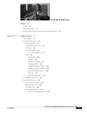
... a Service Request viii Product Overview 1-1 Switch Models 1-1 Front Panel Description 1-3 SFP Module Slots 1-4 10/100/1000 Ethernet Ports 1-4 PoE+ Ports 1-5 Network Modules 1-5 SFP and SFP+ Modules 1-7 LEDs 1-9 System LED 1-10 XPS LED 1-11 Port LEDs and Modes 1-11 USB Console LED 1-13 S-PWR LED (Catalyst 3750-X) 1-14 Master LED (Catalyst 3750-X) 1-14 Stack LED (Catalyst 3750-X) 1-14 PoE+ LED 1-15 Network Module LEDs 1-16 USB Mini-Type B Port 1-17 Rear Panel Description 1-17 RJ-45 Console Port LED 1-18 USB Type A Interface 1-18 StackWise Ports 1-19 Power Supply Modules 1-19 Switch Power Supply...
... a Service Request viii Product Overview 1-1 Switch Models 1-1 Front Panel Description 1-3 SFP Module Slots 1-4 10/100/1000 Ethernet Ports 1-4 PoE+ Ports 1-5 Network Modules 1-5 SFP and SFP+ Modules 1-7 LEDs 1-9 System LED 1-10 XPS LED 1-11 Port LEDs and Modes 1-11 USB Console LED 1-13 S-PWR LED (Catalyst 3750-X) 1-14 Master LED (Catalyst 3750-X) 1-14 Stack LED (Catalyst 3750-X) 1-14 PoE+ LED 1-15 Network Module LEDs 1-16 USB Mini-Type B Port 1-17 Rear Panel Description 1-17 RJ-45 Console Port LED 1-18 USB Type A Interface 1-18 StackWise Ports 1-19 Power Supply Modules 1-19 Switch Power Supply...

Hardware Installation Guide
Page 4
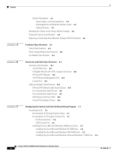
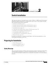
... Shelf-Mounting 2-19 After Installing the Switch 2-19 Connecting to the StackWise Ports (Catalyst 3750-X Switches) 2-20 Connecting to the StackPower Ports (Catalyst 3750-X Switches) 2-21 Connecting the StackPower Ports to the XPS 2200 2-22 Installing a Network Module in a Rack 2-18 Table- Contents 2 C H A P T E R Fan Modules 1-21 XPS Connector 1-21 StackPower Connector (Catalyst 3750-X Switches) 1-22 Management Ports 1-23 Ethernet Management Port 1-23 USB Mini-Type B Port 1-23 Management Options 1-24 Network Configurations 1-24 Switch Installation 2-1 Preparing for Installation 2-1 Safety...
... Shelf-Mounting 2-19 After Installing the Switch 2-19 Connecting to the StackWise Ports (Catalyst 3750-X Switches) 2-20 Connecting to the StackPower Ports (Catalyst 3750-X Switches) 2-21 Connecting the StackPower Ports to the XPS 2200 2-22 Installing a Network Module in a Rack 2-18 Table- Contents 2 C H A P T E R Fan Modules 1-21 XPS Connector 1-21 StackPower Connector (Catalyst 3750-X Switches) 1-22 Management Ports 1-23 Ethernet Management Port 1-23 USB Mini-Type B Port 1-23 Management Options 1-24 Network Configurations 1-24 Switch Installation 2-1 Preparing for Installation 2-1 Safety...
Hardware Installation Guide
Page 6
... B-2 SFP and SFP+ Modules B-2 10/100 Ethernet Management Port B-3 Console Port B-4 Cable and Adapter Specifications B-5 SFP and SFP+ Module Cable Specifications B-5 Four Twisted-Pair Cable Pinouts B-7 Two Twisted-Pair Cable Pinouts B-7 Identifying a Crossover Cable B-8 Console Port Adapter Pinouts B-8 Configuring the Switch with the CLI-Based Setup Program C-1 Accessing the CLI C-1 Accessing the CLI Through Express Setup C-1 Accessing the CLI Through a Console Port C-1 RJ-45 Console Port C-2 USB Console Port C-2 Installing the Cisco Microsoft Windows USB Device Driver C-3 Installing the Cisco...
... B-2 SFP and SFP+ Modules B-2 10/100 Ethernet Management Port B-3 Console Port B-4 Cable and Adapter Specifications B-5 SFP and SFP+ Module Cable Specifications B-5 Four Twisted-Pair Cable Pinouts B-7 Two Twisted-Pair Cable Pinouts B-7 Identifying a Crossover Cable B-8 Console Port Adapter Pinouts B-8 Configuring the Switch with the CLI-Based Setup Program C-1 Accessing the CLI C-1 Accessing the CLI Through Express Setup C-1 Accessing the CLI Through a Console Port C-1 RJ-45 Console Port C-2 USB Console Port C-2 Installing the Cisco Microsoft Windows USB Device Driver C-3 Installing the Cisco...
Hardware Installation Guide
Page 11
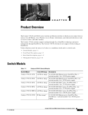
... network module1 slot, 715-W power supply 48 10/100/1000 PoE+2 ports, StackWise Plus, 1 network module1 slot, 1100-W power supply 24 10/100/1000 Ethernet ports, StackWise Plus, StackPower, 1 network module1 slot, 350-W power supply OL-19593-02 Catalyst 3750-X and 3560-X Switch Hardware Installation Guide 1-1 Unless otherwise noted, the term switch refers to a standalone switch and to which you can connect devices such as Cisco IP Phones, Cisco Wireless Access Points, workstations, and other network devices such as servers, routers, and other switches...
... network module1 slot, 715-W power supply 48 10/100/1000 PoE+2 ports, StackWise Plus, 1 network module1 slot, 1100-W power supply 24 10/100/1000 Ethernet ports, StackWise Plus, StackPower, 1 network module1 slot, 350-W power supply OL-19593-02 Catalyst 3750-X and 3560-X Switch Hardware Installation Guide 1-1 Unless otherwise noted, the term switch refers to a standalone switch and to which you can connect devices such as Cisco IP Phones, Cisco Wireless Access Points, workstations, and other network devices such as servers, routers, and other switches...

Hardware Installation Guide
Page 15
...(only Catalyst 3750-X switches) • Configurable support for Cisco intelligent power management, including enhanced power negotiation, power reservation, and per-port power policing Depending on the installed power supply modules, each port can deliver up to 30 W) • Support for Cisco enhanced PoE • Support for prestandard Cisco powered devices • Configuration for StackPower PoE+. Network Modules The switch supports one hot-swappable network module that defines the available PoE and PoE+ power per port. The switch generates logs when you insert or remove a network module...
...(only Catalyst 3750-X switches) • Configurable support for Cisco intelligent power management, including enhanced power negotiation, power reservation, and per-port power policing Depending on the installed power supply modules, each port can deliver up to 30 W) • Support for Cisco enhanced PoE • Support for prestandard Cisco powered devices • Configuration for StackPower PoE+. Network Modules The switch supports one hot-swappable network module that defines the available PoE and PoE+ power per port. The switch generates logs when you insert or remove a network module...
Hardware Installation Guide
Page 28
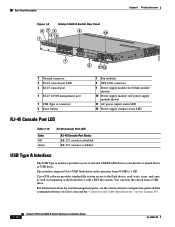
... 6 Reset button 7 Fan modules 8 XPS 2200 connector 9 Power supply module slot (blank module shown) 10 Power supply module (AC power supply module shown) 11 AC power (input) status LED 12 Power supply (output) status LED RJ-45 Console Port LED Table 1-15 Color Off Green RJ-45 Console Port LED RJ-45 Console Port Status RS-232 console is enabled. USB Type A Interface The USB Type A interface provides access to external USB FLASH devices (also known as formatting of the flash device with capacities from a USB drive. The interface supports Cisco USB flash drives with a FAT file system...
... 6 Reset button 7 Fan modules 8 XPS 2200 connector 9 Power supply module slot (blank module shown) 10 Power supply module (AC power supply module shown) 11 AC power (input) status LED 12 Power supply (output) status LED RJ-45 Console Port LED Table 1-15 Color Off Green RJ-45 Console Port LED RJ-45 Console Port Status RS-232 console is enabled. USB Type A Interface The USB Type A interface provides access to external USB FLASH devices (also known as formatting of the flash device with capacities from a USB drive. The interface supports Cisco USB flash drives with a FAT file system...

Hardware Installation Guide
Page 33
... Ethernet connection is immediately disabled, and input from the Ethernet connection. You can restore its operation by using Cisco IOS commands. Use a USB type-A-to-USB 5-pin mini-Type B cable to connect a PC or other device to PC Inactive link POST failure USB Mini-Type B Port The switch provides a USB mini-Type B console connection on the front panel, and the RJ-45 console port on the USB console for installation instructions. Table 1-19 RJ-45 Console Port LED Color Green Off Amber Description Active link to the switch. Removing...
... Ethernet connection is immediately disabled, and input from the Ethernet connection. You can restore its operation by using Cisco IOS commands. Use a USB type-A-to-USB 5-pin mini-Type B cable to connect a PC or other device to PC Inactive link POST failure USB Mini-Type B Port The switch provides a USB mini-Type B console connection on the front panel, and the RJ-45 console port on the USB console for installation instructions. Table 1-19 RJ-45 Console Port LED Color Green Off Amber Description Active link to the switch. Removing...

Hardware Installation Guide
Page 34
This web browser interface offers quick configuration and monitoring from the CLI. For information, see the Getting Started with your SNMP application for network configuration concepts and examples of Management Information Base (MIB) extensions and four Remote Monitoring (RMON) groups. See the switch software configuration guide on Cisco.com and the documentation that simplify the configuration, administration, monitoring, and troubleshooting of Cisco networks. The switch supports a comprehensive set of using Telnet from a Simple Network Management Protocol (SNMP)-...
This web browser interface offers quick configuration and monitoring from the CLI. For information, see the Getting Started with your SNMP application for network configuration concepts and examples of Management Information Base (MIB) extensions and four Remote Monitoring (RMON) groups. See the switch software configuration guide on Cisco.com and the documentation that simplify the configuration, administration, monitoring, and troubleshooting of Cisco networks. The switch supports a comprehensive set of using Telnet from a Simple Network Management Protocol (SNMP)-...
Hardware Installation Guide
Page 35
... • Installing SFP and SFP+ Modules, page 2-24 • Connecting Devices to the Ethernet Ports, page 2-26 • Where to Go Next, page 2-29 For initial switch setup, how to assign the switch IP address, and for powering information, see the switch getting started guide on Cisco.com. OL-19593-02 Catalyst 3750-X and 3560-X Switch Hardware Installation Guide 2-1 Read the topics and perform the procedures in this section before you start the installation procedure. Switch Installation...
... • Installing SFP and SFP+ Modules, page 2-24 • Connecting Devices to the Ethernet Ports, page 2-26 • Where to Go Next, page 2-29 For initial switch setup, how to assign the switch IP address, and for powering information, see the switch getting started guide on Cisco.com. OL-19593-02 Catalyst 3750-X and 3560-X Switch Hardware Installation Guide 2-1 Read the topics and perform the procedures in this section before you start the installation procedure. Switch Installation...

Hardware Installation Guide
Page 54
... connectors are not being used, replace the dust covers. 2-20 Catalyst 3750-X and 3560-X Switch Hardware Installation Guide OL-19593-02 Figure 2-19 Connecting the StackWise Cable in .). When you need to remove the StackWise cable from the StackWise cables and StackWise ports, and store them for future use a Cisco-approved StackWise cable to align the connector correctly. Connecting to the StackWise Ports (Catalyst 3750-X Switches) Chapter 2 Switch Installation Connecting to fully unscrew...
... connectors are not being used, replace the dust covers. 2-20 Catalyst 3750-X and 3560-X Switch Hardware Installation Guide OL-19593-02 Figure 2-19 Connecting the StackWise Cable in .). When you need to remove the StackWise cable from the StackWise cables and StackWise ports, and store them for future use a Cisco-approved StackWise cable to align the connector correctly. Connecting to the StackWise Ports (Catalyst 3750-X Switches) Chapter 2 Switch Installation Connecting to fully unscrew...

Hardware Installation Guide
Page 61
... the switch software configuration guide or the switch command reference on 24- PoE+ inline power supports devices compliant with the IEEE 802.3at standard, by default on page B-5 for cable-pinout descriptions. At this setting, the switch ports configure themselves to other end of the connection. If auto-MDIX is disabled, use Category 3 or Category 4 cable. See Table 1-17 on page 1-20 for the power supply modules required to support PoE and PoE+ on Cisco.com for connections to a switch 10/100/1000 Ethernet port...
... the switch software configuration guide or the switch command reference on 24- PoE+ inline power supports devices compliant with the IEEE 802.3at standard, by default on page B-5 for cable-pinout descriptions. At this setting, the switch ports configure themselves to other end of the connection. If auto-MDIX is disabled, use Category 3 or Category 4 cable. See Table 1-17 on page 1-20 for the power supply modules required to support PoE and PoE+ on Cisco.com for connections to a switch 10/100/1000 Ethernet port...
Hardware Installation Guide
Page 62
... be accessed only through the use this emergency number is 911. Statement 1072 2-28 Catalyst 3750-X and 3560-X Switch Hardware Installation Guide OL-19593-02 Note Many legacy powered devices, including older Cisco IP phones and access points that you might not support PoE when connected to calculate the power supply requirements for a specific PoE configuration. Avoid using such interconnection methods, unless the exposed metal parts are located within a restricted access location and users and service people...
... be accessed only through the use this emergency number is 911. Statement 1072 2-28 Catalyst 3750-X and 3560-X Switch Hardware Installation Guide OL-19593-02 Note Many legacy powered devices, including older Cisco IP phones and access points that you might not support PoE when connected to calculate the power supply requirements for a specific PoE configuration. Avoid using such interconnection methods, unless the exposed metal parts are located within a restricted access location and users and service people...

Hardware Installation Guide
Page 81
..., port-connectivity problems, and overall switch performance. Switch LEDs Look at the port LEDs for some time and then returns to complete POST. It might take several minutes for descriptions of tests that runs automatically to the Factory Default Settings, page 4-5 • Finding the Switch Serial Number, page 4-6 • Replacing a Failed Data Stack Member (Catalyst 3750-X Switches), page 4-6 Diagnosing Problems The switch LEDs provide troubleshooting information about the switch. The System LED blinks green, and the other LEDs turn amber. See...
..., port-connectivity problems, and overall switch performance. Switch LEDs Look at the port LEDs for some time and then returns to complete POST. It might take several minutes for descriptions of tests that runs automatically to the Factory Default Settings, page 4-5 • Finding the Switch Serial Number, page 4-6 • Replacing a Failed Data Stack Member (Catalyst 3750-X Switches), page 4-6 Diagnosing Problems The switch LEDs provide troubleshooting information about the switch. The System LED blinks green, and the other LEDs turn amber. See...

Hardware Installation Guide
Page 84
... and speed settings are mismatched between two switches, between a switch and a router, or between the two devices. Diagnosing Problems Chapter 4 Troubleshooting Note When ordering or using CX1 cables, ensure that the version identifier is 2 or higher. • For long wave SFP+ modules, a mode conditioning patch might mean a speed or duplex mismatch. If a port or interface is received by the switch. It occurs when the traffic sent by the switch is manually...
... and speed settings are mismatched between two switches, between a switch and a router, or between the two devices. Diagnosing Problems Chapter 4 Troubleshooting Note When ordering or using CX1 cables, ensure that the version identifier is 2 or higher. • For long wave SFP+ modules, a mode conditioning patch might mean a speed or duplex mismatch. If a port or interface is received by the switch. It occurs when the traffic sent by the switch is manually...

Hardware Installation Guide
Page 85
... the switch LEDs start blinking when you have configured a new switch with the firmware or software on the NIC. Resetting the Switch to the Factory Default Settings If you try manually setting both sides of the connection. The switch LEDs begin blinking after an additional 8 seconds, and then the switch reboots. If the LEDs do not turn solid green, you can release the Mode button and run Express Setup to the Factory Default Settings Autonegotiation and Network Interface Cards Problems sometimes occur between the switch...
... the switch LEDs start blinking when you have configured a new switch with the firmware or software on the NIC. Resetting the Switch to the Factory Default Settings If you try manually setting both sides of the connection. The switch LEDs begin blinking after an additional 8 seconds, and then the switch reboots. If the LEDs do not turn solid green, you can release the Mode button and run Express Setup to the Factory Default Settings Autonegotiation and Network Interface Cards Problems sometimes occur between the switch...

Hardware Installation Guide
Page 86
...-X Switch Hardware Installation Guide 4-6 OL-19593-02 The replacement switch must be a Catalyst 3750-X switch. 2. Power down the failed switch. Remove AC or DC input power, and if the switch is powered off, and then connect it to the replacement switch. Reinstall any modules and cable connections. 6. Power on the failed switch. 5. Figure 4-1 shows the serial number location. You can also use the show version privileged EXEC command to know the switch serial number. If you need to see the switch software configuration guide on Cisco.com...
...-X Switch Hardware Installation Guide 4-6 OL-19593-02 The replacement switch must be a Catalyst 3750-X switch. 2. Power down the failed switch. Remove AC or DC input power, and if the switch is powered off, and then connect it to the replacement switch. Reinstall any modules and cable connections. 6. Power on the failed switch. 5. Figure 4-1 shows the serial number location. You can also use the show version privileged EXEC command to know the switch serial number. If you need to see the switch software configuration guide on Cisco.com...
Hardware Installation Guide
Page 102
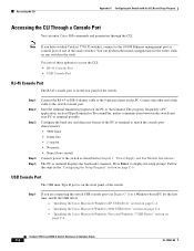
... Windows XP USB Driver" section on page C-4 - You can enter Cisco IOS commands and parameters through the CLI. Accessing the CLI Appendix C Configuring the Switch with the CLI-Based Setup Program Accessing the CLI Through a Console Port You can perform the initial configuration for the first time, install the USB driver. - Note If you are connecting the switch USB console port (see Figure C-1) to the switch console port. Use one of these options to the 10/100 Ethernet management port or console port...
... Windows XP USB Driver" section on page C-4 - You can enter Cisco IOS commands and parameters through the CLI. Accessing the CLI Appendix C Configuring the Switch with the CLI-Based Setup Program Accessing the CLI Through a Console Port You can perform the initial configuration for the first time, install the USB driver. - Note If you are connecting the switch USB console port (see Figure C-1) to the switch console port. Use one of these options to the 10/100 Ethernet management port or console port...

Hardware Installation Guide
Page 108
...: The following configuration command script was created: hostname switch1 enable secret 5 $1$Ulq8$DlA/OiaEbl90WcBPd9cOn1 enable password enable_password line vty 0 15 password terminal-password no snmp-server ! After you complete the setup program, the switch can configure the switch as a command switch later through the CLI, the device manager, or the Network Assistant application. no shutdown ip address 10.4.120.106 255.0.0.0 ! interface Vlan1 no ip routing ! Would you created. You can run the default configuration that you...
...: The following configuration command script was created: hostname switch1 enable secret 5 $1$Ulq8$DlA/OiaEbl90WcBPd9cOn1 enable password enable_password line vty 0 15 password terminal-password no snmp-server ! After you complete the setup program, the switch can configure the switch as a command switch later through the CLI, the device manager, or the Network Assistant application. no shutdown ip address 10.4.120.106 255.0.0.0 ! interface Vlan1 no ip routing ! Would you created. You can run the default configuration that you...

Hardware Installation Guide
Page 109
..., 2-21, 2-22 straight-through four twisted-pair pinout B-7 two twisted-pair pinout B-7 Cisco IOS command-line interface 1-24 Cisco IP Phones, connecting to 2-27 to 2-28 Cisco Network Assistant 1-24 Cisco Power Calculator 2-27 CiscoView 1-24 CLI 1-24 accessing by using Express Setup C-1 accessing through console port C-1 code compliance warning 2-3 command-line interface See CLI connection procedures 2-22 to 2-28 connectors and cables B-1 to 2-27 described 1-4 pinouts B-1 recommended cables 2-27 10/100 Ethernet management port 1-23 10-Gigabit Ethernet module slots connecting devices 2-23 19-
..., 2-21, 2-22 straight-through four twisted-pair pinout B-7 two twisted-pair pinout B-7 Cisco IOS command-line interface 1-24 Cisco IP Phones, connecting to 2-27 to 2-28 Cisco Network Assistant 1-24 Cisco Power Calculator 2-27 CiscoView 1-24 CLI 1-24 accessing by using Express Setup C-1 accessing through console port C-1 code compliance warning 2-3 command-line interface See CLI connection procedures 2-22 to 2-28 connectors and cables B-1 to 2-27 described 1-4 pinouts B-1 recommended cables 2-27 10/100 Ethernet management port 1-23 10-Gigabit Ethernet module slots connecting devices 2-23 19-

Hardware Installation Guide
Page 110
... duplex default setting 2-27 LED 1-11 troubleshooting 4-4 E electrical noise, avoiding 2-4 electromagnetic safety 2-3 Ethernet and fiber cable troubleshooting 4-2 Ethernet management port described 1-23 LED POST results 4-1 expandable power supply See XPS Express Setup accessing CLI by using C-1 for initial switch configuration 2-19 using to clear switch IP address 4-5 F fan module airflow patterns 1-21 described 1-21 installing 3-15 front panel 10/100/1000 Ethernet ports 1-4 clearance 2-3 described 1-3 to 1-17 LEDs 1-9 to 1-16 network modules 1-6 PoE+ ports 1-5 G ground connection 3-9 ground...
... duplex default setting 2-27 LED 1-11 troubleshooting 4-4 E electrical noise, avoiding 2-4 electromagnetic safety 2-3 Ethernet and fiber cable troubleshooting 4-2 Ethernet management port described 1-23 LED POST results 4-1 expandable power supply See XPS Express Setup accessing CLI by using C-1 for initial switch configuration 2-19 using to clear switch IP address 4-5 F fan module airflow patterns 1-21 described 1-21 installing 3-15 front panel 10/100/1000 Ethernet ports 1-4 clearance 2-3 described 1-3 to 1-17 LEDs 1-9 to 1-16 network modules 1-6 PoE+ ports 1-5 G ground connection 3-9 ground...


