
Hardware Installation Guide
Page 4
... 2-11 Wall-Mounting 2-12 Attaching the Brackets to Go Next 2-24 Switch Installation (8- Contents 2 C H A P T E R 3 C H A P T E R Network Configurations 1-21 Switch Installation (24- or Shelf- and 48-Port Switches) 2-1 Preparing for Installation 3-1 Warnings 3-2 Installation Guidelines 3-5 Equipment That You Supply 3-6 Catalyst 3560 Switch Hardware Installation Guide iv OL-6337-07 and 12-Port Switches) 3-1 Preparing for Installation 2-1 Warnings 2-2 Installation Guidelines 2-5 Box Contents 2-6 Tools and...
... 2-11 Wall-Mounting 2-12 Attaching the Brackets to Go Next 2-24 Switch Installation (8- Contents 2 C H A P T E R 3 C H A P T E R Network Configurations 1-21 Switch Installation (24- or Shelf- and 48-Port Switches) 2-1 Preparing for Installation 3-1 Warnings 3-2 Installation Guidelines 3-5 Equipment That You Supply 3-6 Catalyst 3560 Switch Hardware Installation Guide iv OL-6337-07 and 12-Port Switches) 3-1 Preparing for Installation 2-1 Warnings 2-2 Installation Guidelines 2-5 Box Contents 2-6 Tools and...

Hardware Installation Guide
Page 11
... connect devices like workstations, Cisco Wireless Access Points, Cisco IP Phones, and other network devices such as servers, routers, and other network devices. See the switch software configuration guide for examples of the Catalyst 3560 switch. For instructions on setting up your Catalyst switch. Features The 24- and 48-port Catalyst 3560 switches can be deployed as backbone switches, aggregating 10BASE-T and...
... connect devices like workstations, Cisco Wireless Access Points, Cisco IP Phones, and other network devices such as servers, routers, and other network devices. See the switch software configuration guide for examples of the Catalyst 3560 switch. For instructions on setting up your Catalyst switch. Features The 24- and 48-port Catalyst 3560 switches can be deployed as backbone switches, aggregating 10BASE-T and...

Hardware Installation Guide
Page 12
...: • 100BASE-BX10 (only Catalyst 3560 8- Catalyst 3560 Switch Hardware Installation Guide 1-2 OL-6337-07 Features Chapter 1 Product Overview Table 1-1 Catalyst 3560 Switch Model Descriptions Switch Model Description FastEthernet Catalyst 3560-24PS 24 10/100 Power over Ethernet (PoE) ports and 2 small form-factor pluggable (SFP) module slots Catalyst 3560-24TS-S 24 10/100 ports and 2 SFP module slots Catalyst 3560-48PS 48 10...
...: • 100BASE-BX10 (only Catalyst 3560 8- Catalyst 3560 Switch Hardware Installation Guide 1-2 OL-6337-07 Features Chapter 1 Product Overview Table 1-1 Catalyst 3560 Switch Model Descriptions Switch Model Description FastEthernet Catalyst 3560-24PS 24 10/100 Power over Ethernet (PoE) ports and 2 small form-factor pluggable (SFP) module slots Catalyst 3560-24TS-S 24 10/100 ports and 2 SFP module slots Catalyst 3560-48PS 48 10...

Hardware Installation Guide
Page 13
...Port, page 1-10 • LEDs, page 1-11 • Cable Guard, page 1-15 Fast Ethernet Switch Front Panel Descriptions • Catalyst 3560-24PS and 3560V2-24PS Switch Front Panel, Figure 1-1 on page 1-3 • Catalyst 3560-24TS-S, 3560V2-24TS, and 3560V2-24TS-SD Switch Front Panel, Figure 1-2 on page 1-4 • Catalyst 3560-48PS and 3560V2-48PS Switch... 14 13X 15 16 17 18 19 20 21 22 23 24 Catalyst 3560 SERIES PoE-24 23X 14X 24X 1 2 1 2 1 10/100 PoE ports 2 SFP module slots Catalyst 3560 Switch Hardware Installation Guide 1-3 The SFP module slots are autonegotiated. The...
...Port, page 1-10 • LEDs, page 1-11 • Cable Guard, page 1-15 Fast Ethernet Switch Front Panel Descriptions • Catalyst 3560-24PS and 3560V2-24PS Switch Front Panel, Figure 1-1 on page 1-3 • Catalyst 3560-24TS-S, 3560V2-24TS, and 3560V2-24TS-SD Switch Front Panel, Figure 1-2 on page 1-4 • Catalyst 3560-48PS and 3560V2-48PS Switch... 14 13X 15 16 17 18 19 20 21 22 23 24 Catalyst 3560 SERIES PoE-24 23X 14X 24X 1 2 1 2 1 10/100 PoE ports 2 SFP module slots Catalyst 3560 Switch Hardware Installation Guide 1-3 The SFP module slots are autonegotiated. The...

Hardware Installation Guide
Page 14
Figure 1-2 Catalyst 3560-24TS-S, 3560V2-24TS, and 3560V2-24TS-SD Switch Front Panel 126808 SYST RPS STAT DUPLX SPEED MODE 12 1X 34 56 78 9 10 11 12 11X 2X 12X 13 14 13X 15 16 17 18 19 20 21 22 23 24 23X Catalyst 3560 SERIES 14X 24X 1 2 1 2 1 10/100 ports 2 SFP module slots The 10/100...
Figure 1-2 Catalyst 3560-24TS-S, 3560V2-24TS, and 3560V2-24TS-SD Switch Front Panel 126808 SYST RPS STAT DUPLX SPEED MODE 12 1X 34 56 78 9 10 11 12 11X 2X 12X 13 14 13X 15 16 17 18 19 20 21 22 23 24 23X Catalyst 3560 SERIES 14X 24X 1 2 1 2 1 10/100 ports 2 SFP module slots The 10/100...

Hardware Installation Guide
Page 15
... Catalyst 2960 Series 1 157822 1 2 3 1 Console port 2 10/100 PoE ports 3 Dual-purpose port OL-6337-07 Catalyst 3560 Switch Hardware Installation Guide 1-5 Chapter 1 Product Overview Front Panel Description The 10/100 ports on the switch are numbered 1 to 4. The first member of the Catalyst 3560-8PC switch and the Catalyst 3560-12PC-S switch (Figure 1-5 and Figure 1-6). Figure 1-4 Catalyst 3560-48TS-S and 3560V2-48TS Switch...
... Catalyst 2960 Series 1 157822 1 2 3 1 Console port 2 10/100 PoE ports 3 Dual-purpose port OL-6337-07 Catalyst 3560 Switch Hardware Installation Guide 1-5 Chapter 1 Product Overview Front Panel Description The 10/100 ports on the switch are numbered 1 to 4. The first member of the Catalyst 3560-8PC switch and the Catalyst 3560-12PC-S switch (Figure 1-5 and Figure 1-6). Figure 1-4 Catalyst 3560-48TS-S and 3560V2-48TS Switch...

Hardware Installation Guide
Page 16
... 56 78 9 10 11 12 1 2 Catalyst 3560 SERIESPoE-12 1 3 1 Console port 2 10/100 PoE ports 3 Dual-purpose port Gigabit Ethernet Switch Front Panel Descriptions • Catalyst 3560G-24PS Switch Front Panel, Figure 1-7 on page 1-6 • Catalyst 3560G-24TS Switch Front Panel, Figure 1-8 on page 1-7 • Catalyst 3560G-48PS Switch Front Panel, Figure 1-9 on page 1-7 • Catalyst 3560G-48TS Switch Front Panel, Figure 1-10 on...
... 56 78 9 10 11 12 1 2 Catalyst 3560 SERIESPoE-12 1 3 1 Console port 2 10/100 PoE ports 3 Dual-purpose port Gigabit Ethernet Switch Front Panel Descriptions • Catalyst 3560G-24PS Switch Front Panel, Figure 1-7 on page 1-6 • Catalyst 3560G-24TS Switch Front Panel, Figure 1-8 on page 1-7 • Catalyst 3560G-48PS Switch Front Panel, Figure 1-9 on page 1-7 • Catalyst 3560G-48TS Switch Front Panel, Figure 1-10 on...

Hardware Installation Guide
Page 17
... SERIES PoE-48 47X 32X 34X 49 51 48X 50 52 1 2 1 10/100/1000 ports 2 SFP module slots OL-6337-07 Catalyst 3560 Switch Hardware Installation Guide 1-7 Figure 1-8 Catalyst 3560G-24TS Switch Front Panel 119677 SYST RPS STAT DUPLX SPEED MODE 12 1X 34 56 78 9 10 11 12... 11X 2X 12X 13 14 13X 15 16 17 18 19 20 21 22 23 24 23X Catalyst 3560G SERIES 25 14X 27 24X 26 28 1 2 1 10/100/1000 ports...
... SERIES PoE-48 47X 32X 34X 49 51 48X 50 52 1 2 1 10/100/1000 ports 2 SFP module slots OL-6337-07 Catalyst 3560 Switch Hardware Installation Guide 1-7 Figure 1-8 Catalyst 3560G-24TS Switch Front Panel 119677 SYST RPS STAT DUPLX SPEED MODE 12 1X 34 56 78 9 10 11 12... 11X 2X 12X 13 14 13X 15 16 17 18 19 20 21 22 23 24 23X Catalyst 3560G SERIES 25 14X 27 24X 26 28 1 2 1 10/100/1000 ports...

Hardware Installation Guide
Page 18
...20 21 22 23 24 25 26 27 28 29 30 31 32 16X 18X 33 31X 33X 34 35 36 37 38 39 40 41 42 43 44 45 46 47 48 47X 32X 34X Catalyst 3560G SERIES 49 51 48X 50 52 1 2 1 10/100/1000 ports 2 SFP module slots...and configures itself accordingly. You cannot configure half-duplex mode on the Catalyst 3560G-48TS switch are made using uninsulated exposed metal contacts, conductors, or terminals. Catalyst 3560 Switch Hardware Installation Guide 1-8 OL-6337-07 The first member of the pair (port 1) is above port 4, and so on Power over Ethernet (PoE) circuits if interconnections...
...20 21 22 23 24 25 26 27 28 29 30 31 32 16X 18X 33 31X 33X 34 35 36 37 38 39 40 41 42 43 44 45 46 47 48 47X 32X 34X Catalyst 3560G SERIES 49 51 48X 50 52 1 2 1 10/100/1000 ports 2 SFP module slots...and configures itself accordingly. You cannot configure half-duplex mode on the Catalyst 3560G-48TS switch are made using uninsulated exposed metal contacts, conductors, or terminals. Catalyst 3560 Switch Hardware Installation Guide 1-8 OL-6337-07 The first member of the pair (port 1) is above port 4, and so on Power over Ethernet (PoE) circuits if interconnections...

Hardware Installation Guide
Page 19
...for devices compliant with IEEE 802.3af and Cisco prestandard PoE support for Cisco IP Phones and Cisco Aironet Access Points. • Each of the Catalyst 3560-8PC, 3560-12PC-S, 3560-24PS, and 3560V2-24PS switch 10/100 ports or the Catalyst 3560G-24PS switch 10/100/1000 ports deliver up to 15.4 W of approximately ... twisted four-pair, Category 5 cable for proper operation. On the Catalyst 3560-48PS, 3560G-48PS, and 3560V2-48PS switches, any 24 of the 48 10/100 or 10/100/1000 ports delivers 15.4 W of PoE, or any combination of the ports delivers an average of 7.7 W of PoE at the same time,...
...for devices compliant with IEEE 802.3af and Cisco prestandard PoE support for Cisco IP Phones and Cisco Aironet Access Points. • Each of the Catalyst 3560-8PC, 3560-12PC-S, 3560-24PS, and 3560V2-24PS switch 10/100 ports or the Catalyst 3560G-24PS switch 10/100/1000 ports deliver up to 15.4 W of approximately ... twisted four-pair, Category 5 cable for proper operation. On the Catalyst 3560-48PS, 3560G-48PS, and 3560V2-48PS switches, any 24 of the 48 10/100 or 10/100/1000 ports delivers 15.4 W of PoE, or any combination of the ports delivers an average of 7.7 W of PoE at the same time,...
Hardware Installation Guide
Page 33
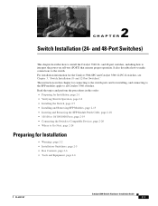
..., page 2-5 • Box Contents, page 2-6 • Tools and Equipment, page 2-6 OL-6337-07 Catalyst 3560 Switch Hardware Installation Guide 2-1 2 C H A P T E R Switch Installation (24- It also describes how to make connections to install the Catalyst 3560 24- and 48-port switches, including how to all Catalyst 3560 switches. Read the topics and perform the procedures in this order: • Preparing for Installation...
..., page 2-5 • Box Contents, page 2-6 • Tools and Equipment, page 2-6 OL-6337-07 Catalyst 3560 Switch Hardware Installation Guide 2-1 2 C H A P T E R Switch Installation (24- It also describes how to make connections to install the Catalyst 3560 24- and 48-port switches, including how to all Catalyst 3560 switches. Read the topics and perform the procedures in this order: • Preparing for Installation...
Hardware Installation Guide
Page 34
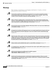
... follow the correct procedures could result in the Regulatory Compliance and Safety Information for Installation Chapter 2 Switch Installation (24- Statement 378 Catalyst 3560 Switch Hardware Installation Guide 2-2 OL-6337-07 Do not operate the system unless all cards and faceplates ...instructions carefully before beginning installation. Statement 265 Warning Attach only the following Cisco RPS model to power lines, remove jewelry (including rings, necklaces, and watches). and 48-Port Switches) Warnings These warnings are in a central office environment. Statement 156...
... follow the correct procedures could result in the Regulatory Compliance and Safety Information for Installation Chapter 2 Switch Installation (24- Statement 378 Catalyst 3560 Switch Hardware Installation Guide 2-2 OL-6337-07 Do not operate the system unless all cards and faceplates ...instructions carefully before beginning installation. Statement 265 Warning Attach only the following Cisco RPS model to power lines, remove jewelry (including rings, necklaces, and watches). and 48-Port Switches) Warnings These warnings are in a central office environment. Statement 156...

Hardware Installation Guide
Page 35
...only through the use of a special tool, lock and key, or other means of lightning activity. Statement 1022 OL-6337-07 Catalyst 3560 Switch Hardware Installation Guide 2-3 Statement 1004 Warning This product relies on the system or connect or disconnect cables during periods of security. ... the rack. • When mounting this unit in the rack. The following procedures, ensure that the system remains stable. and 48-Port Switches) Preparing for Installation Warning Do not work on the building's installation for installation in the fixed wiring. A restricted access area can be...
...only through the use of a special tool, lock and key, or other means of lightning activity. Statement 1022 OL-6337-07 Catalyst 3560 Switch Hardware Installation Guide 2-3 Statement 1004 Warning This product relies on the system or connect or disconnect cables during periods of security. ... the rack. • When mounting this unit in the rack. The following procedures, ensure that the system remains stable. and 48-Port Switches) Preparing for Installation Warning Do not work on the building's installation for installation in the fixed wiring. A restricted access area can be...

Hardware Installation Guide
Page 36
...can be removed to install, replace, or service this equipment. Statement 1074 Catalyst 3560 Switch Hardware Installation Guide 2-4 OL-6337-07 All connections must always be allowed ... an approved network termination unit with standard practices for Installation Chapter 2 Switch Installation (24- Statement 1072 Warning No user-serviceable parts inside. Statement 1073 Warning ... exposed metal contacts, conductors, or terminals. Preparing for preventing accidents. and 48-Port Switches) Warning This equipment must comply with local and national electrical codes. Statement 1024...
...can be removed to install, replace, or service this equipment. Statement 1074 Catalyst 3560 Switch Hardware Installation Guide 2-4 OL-6337-07 All connections must always be allowed ... an approved network termination unit with standard practices for Installation Chapter 2 Switch Installation (24- Statement 1072 Warning No user-serviceable parts inside. Statement 1073 Warning ... exposed metal contacts, conductors, or terminals. Preparing for preventing accidents. and 48-Port Switches) Warning This equipment must comply with local and national electrical codes. Statement 1024...

Hardware Installation Guide
Page 37
... other devices that exit from the switch to avoid overloading the receiver. Chapter 2 Switch Installation (24- Note The grounding architecture of this product is within the ranges listed in Table B-1 on page B-4, which lists the cable specifications for 1000BASE-X and 100BASE-X SFP modules for unrestricted cabling. - Catalyst 3560 switch SFP ports use shorter lengths of an...
... other devices that exit from the switch to avoid overloading the receiver. Chapter 2 Switch Installation (24- Note The grounding architecture of this product is within the ranges listed in Table B-1 on page B-4, which lists the cable specifications for 1000BASE-X and 100BASE-X SFP modules for unrestricted cabling. - Catalyst 3560 switch SFP ports use shorter lengths of an...

Hardware Installation Guide
Page 38
...Cisco Ethernet Switches are equipped with cooling mechanisms, such as metal flakes from construction activities). See Section 3, "Running Express Setup," in the getting started guide for more information. Set the RPS to rack-mount the switch. Catalyst 3560-8PC switch-8 10/100 PoE ports and 1 dual-purpose port... applies to the switch, put the RPS in an environment as free as possible from dust and foreign conductive material (such as fans and blowers. Verifying Switch Operation Chapter 2 Switch Installation (24- Statement 370 Catalyst 3560 Switch Hardware Installation Guide ...
...Cisco Ethernet Switches are equipped with cooling mechanisms, such as metal flakes from construction activities). See Section 3, "Running Express Setup," in the getting started guide for more information. Set the RPS to rack-mount the switch. Catalyst 3560-8PC switch-8 10/100 PoE ports and 1 dual-purpose port... applies to the switch, put the RPS in an environment as free as possible from dust and foreign conductive material (such as fans and blowers. Verifying Switch Operation Chapter 2 Switch Installation (24- Statement 370 Catalyst 3560 Switch Hardware Installation Guide ...
Hardware Installation Guide
Page 39
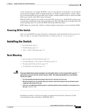
and 48-Port Switches) Installing the Switch As the switch powers on, it is provided with stabilizing devices, install the stabilizers before mounting or servicing the unit in the "Installing the Switch" section on a shelf as described in the rack. ...Switch Installation (24- When the switch begins POST, the System, RPS, Status, Duplex, and Speed LEDs turn off and then reflect the switch operating status. When the POST completes successfully, the System LED remains green. OL-6337-07 Catalyst 3560 Switch Hardware Installation Guide 2-7 LEDs can blink during the test. Call Cisco...
and 48-Port Switches) Installing the Switch As the switch powers on, it is provided with stabilizing devices, install the stabilizers before mounting or servicing the unit in the "Installing the Switch" section on a shelf as described in the rack. ...Switch Installation (24- When the switch begins POST, the System, RPS, Status, Duplex, and Speed LEDs turn off and then reflect the switch operating status. When the POST completes successfully, the System LED remains green. OL-6337-07 Catalyst 3560 Switch Hardware Installation Guide 2-7 LEDs can blink during the test. Call Cisco...

Hardware Installation Guide
Page 40
...-13248-01. Installing the Switch Chapter 2 Switch Installation (24- Figure 2-2 through Figure 2-7 show how to attach each type bracket to the Catalyst 3560 Switch The bracket orientation and the brackets that you use depend on whether you are attaching the brackets for 19-Inch Racks to the opposite side. and 48-Port Switches) Removing Screws from the...
...-13248-01. Installing the Switch Chapter 2 Switch Installation (24- Figure 2-2 through Figure 2-7 show how to attach each type bracket to the Catalyst 3560 Switch The bracket orientation and the brackets that you use depend on whether you are attaching the brackets for 19-Inch Racks to the opposite side. and 48-Port Switches) Removing Screws from the...
Hardware Installation Guide
Page 41
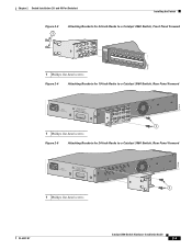
...Port Switches) Installing the Switch Figure 2-3 1 Attaching Brackets for 24-Inch Racks to a Catalyst 3560 Switch, Front Panel Forward 1 Phillips flat-head screws SYST RPS STAT DUPLX SPEED PoE MODE 1 1X 23 45 67 8 9 10 11 12 13 14 15 16 15X 2X 16X 97918 Figure 2-4 Attaching Brackets for 19-Inch Racks to a Catalyst 3560 Switch[email protected] 1 1 Phillips flat-head screws Figure 2-5 Attaching Brackets for 24-Inch Racks to a Catalyst 3560 Switch, Rear Panel Forward 97920 5.0A1-20R.05A-A2T,0IN500GV-6~0 HZ [email protected]...
...Port Switches) Installing the Switch Figure 2-3 1 Attaching Brackets for 24-Inch Racks to a Catalyst 3560 Switch, Front Panel Forward 1 Phillips flat-head screws SYST RPS STAT DUPLX SPEED PoE MODE 1 1X 23 45 67 8 9 10 11 12 13 14 15 16 15X 2X 16X 97918 Figure 2-4 Attaching Brackets for 19-Inch Racks to a Catalyst 3560 Switch[email protected] 1 1 Phillips flat-head screws Figure 2-5 Attaching Brackets for 24-Inch Racks to a Catalyst 3560 Switch, Rear Panel Forward 97920 5.0A1-20R.05A-A2T,0IN500GV-6~0 HZ [email protected]...
Hardware Installation Guide
Page 42
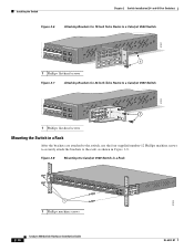
...Port Switches) Figure 2-6 Attaching Brackets for 19-Inch Telco Racks to a Catalyst 3560 Switch 97921 40 41 42 43 44 45 46 47 48 47X Catalyst 3560 SERIES PoE-48 1 3 48X 2 4 1 1 Phillips flat-head screws Figure 2-7 Attaching Brackets for 24-Inch Telco Racks to a Catalyst 3560 Switch 97922 40 41 42 43 44 45 46 47 48 47X Catalyst... 3560 SERIES PoE-48 1 3 48X 2 1 4 1 Phillips flat-head screws Mounting the Switch in a Rack After the brackets are attached to the switch,...
...Port Switches) Figure 2-6 Attaching Brackets for 19-Inch Telco Racks to a Catalyst 3560 Switch 97921 40 41 42 43 44 45 46 47 48 47X Catalyst 3560 SERIES PoE-48 1 3 48X 2 4 1 1 Phillips flat-head screws Figure 2-7 Attaching Brackets for 24-Inch Telco Racks to a Catalyst 3560 Switch 97922 40 41 42 43 44 45 46 47 48 47X Catalyst... 3560 SERIES PoE-48 1 3 48X 2 1 4 1 Phillips flat-head screws Mounting the Switch in a Rack After the brackets are attached to the switch,...


