Hardware Installation Guide
Page 2
... trademarks mentioned in a residential installation. The use of the FCC rules. Catalyst 3560 Switch Hardware Installation Guide © 2004-2010 Cisco Systems, Inc. ALL STATEMENTS, INFORMATION, AND RECOMMENDATIONS IN THIS MANUAL ARE ... CCENT, CCSI, Cisco Eos, Cisco Explorer, Cisco HealthPresence, Cisco IronPort, the Cisco logo, Cisco Nurse Connect, Cisco Pulse, Cisco SensorBase, Cisco StackPower, Cisco StadiumVision, Cisco TelePresence, Cisco TrustSec, Cisco Unified Computing System, Cisco WebEx, DCE, Flip Channels, Flip for illustrative purposes only. These specifications are shown for ...
... trademarks mentioned in a residential installation. The use of the FCC rules. Catalyst 3560 Switch Hardware Installation Guide © 2004-2010 Cisco Systems, Inc. ALL STATEMENTS, INFORMATION, AND RECOMMENDATIONS IN THIS MANUAL ARE ... CCENT, CCSI, Cisco Eos, Cisco Explorer, Cisco HealthPresence, Cisco IronPort, the Cisco logo, Cisco Nurse Connect, Cisco Pulse, Cisco SensorBase, Cisco StackPower, Cisco StadiumVision, Cisco TelePresence, Cisco TrustSec, Cisco Unified Computing System, Cisco WebEx, DCE, Flip Channels, Flip for illustrative purposes only. These specifications are shown for ...

Hardware Installation Guide
Page 6
... and 10/100/1000 Ports B-1 SFP Module Ports B-2 Dual-Purpose Ports B-3 Console Port B-3 Cable and Adapter Specifications B-4 SFP Module Cable Specifications B-4 Two Twisted-Pair Cable Pinouts B-5 Four Twisted-Pair Cable Pinouts for 1000BASE-T Ports B-6 Identifying a Crossover Cable... to DC Power C-1 Connecting to DC Power C-1 Preparing for Installation C-2 Grounding the Switch C-2 Wiring the DC-Input Power Source C-5 Configuring the Switch with the CLI-Based Setup Program D-1 Preparing for Setup D-1 Completing the Setup Program D-3 Catalyst 3560 Switch Hardware Installation Guide vi OL-6337-07
... and 10/100/1000 Ports B-1 SFP Module Ports B-2 Dual-Purpose Ports B-3 Console Port B-3 Cable and Adapter Specifications B-4 SFP Module Cable Specifications B-4 Two Twisted-Pair Cable Pinouts B-5 Four Twisted-Pair Cable Pinouts for 1000BASE-T Ports B-6 Identifying a Crossover Cable... to DC Power C-1 Connecting to DC Power C-1 Preparing for Installation C-2 Grounding the Switch C-2 Wiring the DC-Input Power Source C-5 Configuring the Switch with the CLI-Based Setup Program D-1 Preparing for Setup D-1 Completing the Setup Program D-3 Catalyst 3560 Switch Hardware Installation Guide vi OL-6337-07

Hardware Installation Guide
Page 19
...for devices compliant with IEEE 802.3af and Cisco prestandard PoE support for Cisco IP Phones and Cisco Aironet Access Points. • Each of the Catalyst 3560-8PC, 3560-12PC-S, 3560-24PS, and 3560V2-24PS switch 10/100 ports or the Catalyst 3560G-24PS switch 10/100/1000 ports deliver up to ...described in Appendix B, "Connector and Cable Specifications." • You can use the mdix auto interface configuration command to a copper 10/100, 10/100/1000, or 1000BASE-T SFP module port on the switch, regardless of the type of device on switches running Cisco IOS Release 12.2(18)SE or later...
...for devices compliant with IEEE 802.3af and Cisco prestandard PoE support for Cisco IP Phones and Cisco Aironet Access Points. • Each of the Catalyst 3560-8PC, 3560-12PC-S, 3560-24PS, and 3560V2-24PS switch 10/100 ports or the Catalyst 3560G-24PS switch 10/100/1000 ports deliver up to ...described in Appendix B, "Connector and Cable Specifications." • You can use the mdix auto interface configuration command to a copper 10/100, 10/100/1000, or 1000BASE-T SFP module port on the switch, regardless of the type of device on switches running Cisco IOS Release 12.2(18)SE or later...

Hardware Installation Guide
Page 20
...the SFP module patch cable. Front Panel Description Chapter 1 Product Overview Many legacy powered devices, including older Cisco IP phones and access points that first links up. To connect a Catalyst 3560 switch to a copper SFP module. Use a Category 5 cable with LC or MT-RJ connectors to connect ...SFP Module Cable Specifications" section on page B-4. Each uplink port has two LEDs. One shows the status of the RJ-45 port, and one connector of the pair at each end (see Figure 1-11). Dual-Purpose Port You can connect only two Catalyst 3560 switches. SFP Module Slots...
...the SFP module patch cable. Front Panel Description Chapter 1 Product Overview Many legacy powered devices, including older Cisco IP phones and access points that first links up. To connect a Catalyst 3560 switch to a copper SFP module. Use a Category 5 cable with LC or MT-RJ connectors to connect ...SFP Module Cable Specifications" section on page B-4. Each uplink port has two LEDs. One shows the status of the RJ-45 port, and one connector of the pair at each end (see Figure 1-11). Dual-Purpose Port You can connect only two Catalyst 3560 switches. SFP Module Slots...

Hardware Installation Guide
Page 29
Note When an RPS is connected to the Catalyst 3560V2-24TS-SD switch, the switch is 675 W. It automatically senses when the internal power supply of a connected switch fails and provides power to the failed switch, preventing loss of the console port and the supplied RJ-45-to-... each Catalyst 3560 switch, see the "Connector and Cable Specifications" section on page 1-19 Connect the switch and the Cisco RPS to the same AC power source. The maximum output power depends on Cisco.com: http://www.cisco.com/en/US/products/ps7148/prod_installation_guides_list.html Cisco RPS 2300 The Cisco RPS...
Note When an RPS is connected to the Catalyst 3560V2-24TS-SD switch, the switch is 675 W. It automatically senses when the internal power supply of a connected switch fails and provides power to the failed switch, preventing loss of the console port and the supplied RJ-45-to-... each Catalyst 3560 switch, see the "Connector and Cable Specifications" section on page 1-19 Connect the switch and the Cisco RPS to the same AC power source. The maximum output power depends on Cisco.com: http://www.cisco.com/en/US/products/ps7148/prod_installation_guides_list.html Cisco RPS 2300 The Cisco RPS...

Hardware Installation Guide
Page 37
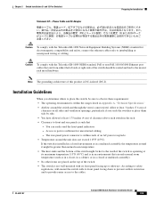
...8226; Temperature around it might be up to the nearest rack metal hardware. OL-6337-07 Catalyst 3560 Switch Hardware Installation Guide 2-5 and 48-Port Switches) Statement 371-Power Cable and AC Adapter Preparing for Installation Caution To comply with the Telcordia ...attenuator in Appendix A, "Technical Specifications." • Airflow around the switch and through the vents is away from the switch to connected devices can easily read the front-panel indicators. - If the switch is sufficient for the Catalyst 3560 switch. Catalyst 3560 switch SFP ports use shorter lengths...
...8226; Temperature around it might be up to the nearest rack metal hardware. OL-6337-07 Catalyst 3560 Switch Hardware Installation Guide 2-5 and 48-Port Switches) Statement 371-Power Cable and AC Adapter Preparing for Installation Caution To comply with the Telcordia ...attenuator in Appendix A, "Technical Specifications." • Airflow around the switch and through the vents is away from the switch to connected devices can easily read the front-panel indicators. - If the switch is sufficient for the Catalyst 3560 switch. Catalyst 3560 switch SFP ports use shorter lengths...
Hardware Installation Guide
Page 47
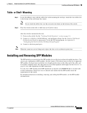
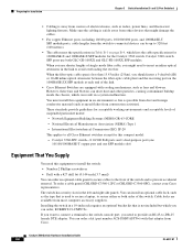
...to a 10/100 or 10/100/1000 port, and run Express Setup. See the Catalyst 3560 Switch Getting Started Guide for reliable communications, the cable must match the wave-length specifications on the front and provide uplink interfaces. Connect to identify and validate that the SFP .... See the Table B-1 on the switch. OL-6337-07 Catalyst 3560 Switch Hardware Installation Guide 2-15 Power on page B-4 for cable stipulations for the list of SFP modules. Use only Cisco SFP modules. For detailed instructions on the bottom of the switch near an AC power source. Mounting ...
...to a 10/100 or 10/100/1000 port, and run Express Setup. See the Catalyst 3560 Switch Getting Started Guide for reliable communications, the cable must match the wave-length specifications on the front and provide uplink interfaces. Connect to identify and validate that the SFP .... See the Table B-1 on the switch. OL-6337-07 Catalyst 3560 Switch Hardware Installation Guide 2-15 Power on page B-4 for cable stipulations for the list of SFP modules. Use only Cisco SFP modules. For detailed instructions on the bottom of the switch near an AC power source. Mounting ...
Hardware Installation Guide
Page 52
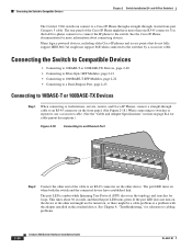
... to 10BASE-T or 100BASE-TX Devices Step 1 When connecting to switches or repeaters, use a crossover cable. (See the "Cable and Adapter Specifications" section on , the device at the other device. Connecting the Switch to the switch. and 48-Port Switches) The Catalyst 3560 switch can connect to a Cisco IP Phone through a straight-through cable to an RJ-45...
... to 10BASE-T or 100BASE-TX Devices Step 1 When connecting to switches or repeaters, use a crossover cable. (See the "Cable and Adapter Specifications" section on , the device at the other device. Connecting the Switch to the switch. and 48-Port Switches) The Catalyst 3560 switch can connect to a Cisco IP Phone through a straight-through cable to an RJ-45...
Hardware Installation Guide
Page 53
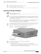
...cable until you understand the port and cabling stipulations in the "Installation Guidelines" section on page 2-5. OL-6337-07 Catalyst 3560 Switch Hardware Installation Guide 2-21 Step 1 Remove the rubber plugs from the module port and fiber-optic cable, and store ... 2-19). and 48-Port Switches) Connecting the Switch to connect each device. Chapter 2 Switch Installation (24- Step 4 Repeat Steps 1 through 3 to Compatible Devices Step 3 Reconfigure and reboot the connected device, if necessary. See Appendix B, "Connector and Cable Specifications," for information about 30 seconds...
...cable until you understand the port and cabling stipulations in the "Installation Guidelines" section on page 2-5. OL-6337-07 Catalyst 3560 Switch Hardware Installation Guide 2-21 Step 1 Remove the rubber plugs from the module port and fiber-optic cable, and store ... 2-19). and 48-Port Switches) Connecting the Switch to connect each device. Chapter 2 Switch Installation (24- Step 4 Repeat Steps 1 through 3 to Compatible Devices Step 3 Reconfigure and reboot the connected device, if necessary. See Appendix B, "Connector and Cable Specifications," for information about 30 seconds...

Hardware Installation Guide
Page 57
...; Box Contents, page 3-7 • Tools and Equipment, page 3-7 OL-6337-07 Catalyst 3560 Switch Hardware Installation Guide 3-1 It also describes how to Compatible Devices" section on self-test (POST) that ensures proper operation. Note This chapter describes the installation information specific to interpret the power-on page 2-20 Preparing for Installation, page 3-1 •...
...; Box Contents, page 3-7 • Tools and Equipment, page 3-7 OL-6337-07 Catalyst 3560 Switch Hardware Installation Guide 3-1 It also describes how to Compatible Devices" section on self-test (POST) that ensures proper operation. Note This chapter describes the installation information specific to interpret the power-on page 2-20 Preparing for Installation, page 3-1 •...
Hardware Installation Guide
Page 61
...wall-mounted with its front panel facing up or sideways. If the switch is operating at least 1.75 inches (4 cm) of the switch should be routed and tied to the cables. OL-6337-07 Catalyst 3560 Switch Hardware Installation Guide 3-5 Caution To comply with the Telcordia GR-1089.... The rear-panel power connector is within the ranges listed in Appendix A, "Technical Specifications." • Airflow around the unit does not exceed 113°F (45°C). and 12-Port Switches) Statement 371-Power Cable and AC Adapter Preparing for Installation Caution To comply with its...
...wall-mounted with its front panel facing up or sideways. If the switch is operating at least 1.75 inches (4 cm) of the switch should be routed and tied to the cables. OL-6337-07 Catalyst 3560 Switch Hardware Installation Guide 3-5 Caution To comply with the Telcordia GR-1089.... The rear-panel power connector is within the ranges listed in Appendix A, "Technical Specifications." • Airflow around the unit does not exceed 113°F (45°C). and 12-Port Switches) Statement 371-Power Cable and AC Adapter Preparing for Installation Caution To comply with its...
Hardware Installation Guide
Page 62
...ZX SFP module at each end of suspended particulate matter: - These standards provide guidelines for the Catalyst 3560 switch. Catalyst 3560 switch SFP ports use shorter lengths of the switch. When the fiber-optic cable span is safely away from other particles, causing contaminant buildup inside...the receiving port on page B-4, which lists the cable specifications for 1000BASE-X and 100BASE-X SFP modules for acceptable working environments and acceptable levels of the link. • Cisco Ethernet Switches are available from the switch to -DB-25 female DTE adapter. You must ...
...ZX SFP module at each end of suspended particulate matter: - These standards provide guidelines for the Catalyst 3560 switch. Catalyst 3560 switch SFP ports use shorter lengths of the switch. When the fiber-optic cable span is safely away from other particles, causing contaminant buildup inside...the receiving port on page B-4, which lists the cable specifications for 1000BASE-X and 100BASE-X SFP modules for acceptable working environments and acceptable levels of the link. • Cisco Ethernet Switches are available from the switch to -DB-25 female DTE adapter. You must ...
Hardware Installation Guide
Page 79
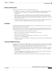
... if necessary. • Make sure that both devices have power. • Verify that you are using the correct cable type. OL-6337-07 Catalyst 3560 Switch Hardware Installation Guide 4-3 Use either Category 5, Category 5e, or Category 6 UTP for 10/100 or 10/100/1000 Mb/s connections. •... that the module meets the requirements for these items: • Bad or incorrect SFP module. See Appendix B, "Connector and Cable Specifications." Transceiver Module Port Issues Use only Cisco small form-factor (SFP) modules on the switch. Exchange the suspect module with security information.
... if necessary. • Make sure that both devices have power. • Verify that you are using the correct cable type. OL-6337-07 Catalyst 3560 Switch Hardware Installation Guide 4-3 Use either Category 5, Category 5e, or Category 6 UTP for 10/100 or 10/100/1000 Mb/s connections. •... that the module meets the requirements for these items: • Bad or incorrect SFP module. See Appendix B, "Connector and Cable Specifications." Transceiver Module Port Issues Use only Cisco small form-factor (SFP) modules on the switch. Exchange the suspect module with security information.
Hardware Installation Guide
Page 81
...; If a remote device does not autonegotiate, configure the duplex settings on your switch to the factory default settings: 1. OL-6337-07 Catalyst 3560 Switch Hardware Installation Guide 4-5 See Appendix B, "Connector and Cable Specifications," for devices such as laptop computers or other devices to also be causing the...parameter on the connected port. • A port is set to autonegotiate, and the connected port is stored on the switch. To maximize switch performance and to match. The speed parameter can omit this does not solve the problem, the firmware or software on the...
...; If a remote device does not autonegotiate, configure the duplex settings on your switch to the factory default settings: 1. OL-6337-07 Catalyst 3560 Switch Hardware Installation Guide 4-5 See Appendix B, "Connector and Cable Specifications," for devices such as laptop computers or other devices to also be causing the...parameter on the connected port. • A port is set to autonegotiate, and the connected port is stored on the switch. To maximize switch performance and to match. The speed parameter can omit this does not solve the problem, the firmware or software on the...
Hardware Installation Guide
Page 85
... A-2, Specifications for the Catalyst 3560-48PS Switch • Table A-4 on page A-3, Specifications for the Catalyst 3560-24TS-S Switch • Table A-5 on page A-3, Specifications for the Catalyst 3560-48TS-S Switch • Table A-6 on page A-3, Specifications for the Catalyst 3560-8PC and Catalyst 3560-12PC Switches • Table A-7 on page A-4, Specifications for the Catalyst 3560G-24TS Switch • Table A-8 on page A-4, Specifications for the Catalyst 3560G-24PS Switch • Table A-9 on page A-5, Specifications for...
... A-2, Specifications for the Catalyst 3560-48PS Switch • Table A-4 on page A-3, Specifications for the Catalyst 3560-24TS-S Switch • Table A-5 on page A-3, Specifications for the Catalyst 3560-48TS-S Switch • Table A-6 on page A-3, Specifications for the Catalyst 3560-8PC and Catalyst 3560-12PC Switches • Table A-7 on page A-4, Specifications for the Catalyst 3560G-24TS Switch • Table A-8 on page A-4, Specifications for the Catalyst 3560G-24PS Switch • Table A-9 on page A-5, Specifications for...
Hardware Installation Guide
Page 86
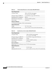
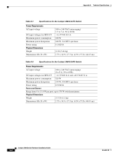
Appendix A Technical Specifications Table A-2 Technical Specifications for the Catalyst 3560-24PS Switch Power Requirements AC input voltage 100 to 240 VAC (autoranging) 5.5 A to 2.8 A, 50 to 60 Hz DC input voltage for RPS 675 +12 V @7.5 A and -48 V @7.8 A... Physical Dimensions Weight 11.3 lb (5.14 kg) Dimensions (H x D x W) 1.73 x 11.81 x 17.5 in. (4.39 x 30 x 44.45 cm) Table A-3 Specifications for the Catalyst 3560-48PS Switch Power Requirements AC input voltage 100 to 240 VAC (autoranging) 5.5 to 2.8 A, 50 to 60 Hz DC input voltages for RPS 675 +12 V @7.5 A and -48 V @7.8 A...
Appendix A Technical Specifications Table A-2 Technical Specifications for the Catalyst 3560-24PS Switch Power Requirements AC input voltage 100 to 240 VAC (autoranging) 5.5 A to 2.8 A, 50 to 60 Hz DC input voltage for RPS 675 +12 V @7.5 A and -48 V @7.8 A... Physical Dimensions Weight 11.3 lb (5.14 kg) Dimensions (H x D x W) 1.73 x 11.81 x 17.5 in. (4.39 x 30 x 44.45 cm) Table A-3 Specifications for the Catalyst 3560-48PS Switch Power Requirements AC input voltage 100 to 240 VAC (autoranging) 5.5 to 2.8 A, 50 to 60 Hz DC input voltages for RPS 675 +12 V @7.5 A and -48 V @7.8 A...
Hardware Installation Guide
Page 87
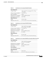
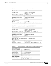
Appendix A Technical Specifications OL-6337-07 Table A-4 Specifications for the Catalyst 3560-24TS-S Switch Power Requirements AC input voltage DC input voltages for RPS 675 Power consumption Maximum power consumption Maximum power dissipation Physical Dimensions ...45 W, 154 BTUs per hour 0.075 KVA 8.5 lb (3.9 kg) 1.73 x 11.81 x 17.5 in. (4.39 x 30 x 44.45 cm) Table A-5 Specifications for the Catalyst 3560-48TS-S Switch Power Requirements AC input voltage DC input voltages for RPS 675 Maximum power consumption Maximum power dissipation Power rating Physical Dimensions Weight Dimensions...
Appendix A Technical Specifications OL-6337-07 Table A-4 Specifications for the Catalyst 3560-24TS-S Switch Power Requirements AC input voltage DC input voltages for RPS 675 Power consumption Maximum power consumption Maximum power dissipation Physical Dimensions ...45 W, 154 BTUs per hour 0.075 KVA 8.5 lb (3.9 kg) 1.73 x 11.81 x 17.5 in. (4.39 x 30 x 44.45 cm) Table A-5 Specifications for the Catalyst 3560-48TS-S Switch Power Requirements AC input voltage DC input voltages for RPS 675 Maximum power consumption Maximum power dissipation Power rating Physical Dimensions Weight Dimensions...
Hardware Installation Guide
Page 88
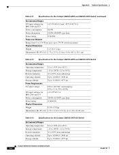
Appendix A Technical Specifications Table A-7 Specifications for the Catalyst 3560G-24TS Switch Power Requirements AC input voltage DC input voltages for RPS 675 Maximum power consumption Maximum power dissipation Power rating Physical Dimensions Weight Dimensions (H x D x W) 100 to ... V @10.5 A 100 W 100 W, 314 BTUs per hour 0.10 KVA 12 lb (5.44 kg) 1.73 x 14.9 x 17.5 in. (4.39 x 37.8 x 44.45 cm) Table A-8 Specifications for the Catalyst 3560G-24PS Switch Power Requirements AC input voltage 100 to 240 VAC (autoranging) 4 to 8 A, 50 to 60 Hz DC input voltages for RPS 675 +12 V @14...
Appendix A Technical Specifications Table A-7 Specifications for the Catalyst 3560G-24TS Switch Power Requirements AC input voltage DC input voltages for RPS 675 Maximum power consumption Maximum power dissipation Power rating Physical Dimensions Weight Dimensions (H x D x W) 100 to ... V @10.5 A 100 W 100 W, 314 BTUs per hour 0.10 KVA 12 lb (5.44 kg) 1.73 x 14.9 x 17.5 in. (4.39 x 37.8 x 44.45 cm) Table A-8 Specifications for the Catalyst 3560G-24PS Switch Power Requirements AC input voltage 100 to 240 VAC (autoranging) 4 to 8 A, 50 to 60 Hz DC input voltages for RPS 675 +12 V @14...
Hardware Installation Guide
Page 89
...BTUs per hour 0.16 KVA 14 lb (6.4 kg) 1.73 x 16.1 x 17.5 in. (4.39 x 40.9 x 44.45 cm) Table A-10 Specifications for the Catalyst 3560G-48PS Switch Power Requirements AC input voltage 100 to 240 VAC (autoranging) 4 to 8 A, 50 to 60 Hz DC input voltages for RPS 675 +12 V @... (H x D x W) 1.73 x 16.1 x 17.5 in. (4.39 x 40.9 x 44.45 cm) Table A-11 Specifications for the Catalyst 3560V2-48PS and 3560V2-24PS Switch Environmental Ranges Operating temperature Storage temperature Relative humidity Operating altitude Storage altitude Power Requirements AC input voltage 32 to 113°F (0 to 45...
...BTUs per hour 0.16 KVA 14 lb (6.4 kg) 1.73 x 16.1 x 17.5 in. (4.39 x 40.9 x 44.45 cm) Table A-10 Specifications for the Catalyst 3560G-48PS Switch Power Requirements AC input voltage 100 to 240 VAC (autoranging) 4 to 8 A, 50 to 60 Hz DC input voltages for RPS 675 +12 V @... (H x D x W) 1.73 x 16.1 x 17.5 in. (4.39 x 40.9 x 44.45 cm) Table A-11 Specifications for the Catalyst 3560V2-48PS and 3560V2-24PS Switch Environmental Ranges Operating temperature Storage temperature Relative humidity Operating altitude Storage altitude Power Requirements AC input voltage 32 to 113°F (0 to 45...
Hardware Installation Guide
Page 90
... Dimensions (H x W x D) 1.73 x 17.5 x 11.8 in. (4.4 x 44.5 x 30.1 cm) Table A-12 Specifications for the Catalyst 3560V2-48TS and 3560V2-24TS Switch Environmental Ranges Operating temperature 32 to 113°F (0 to 45°C) Storage temperature -13 to 158°F (-25 to 70°C)... kg) Dimensions (H x W x D) 1.73 x 11.81 x 17.5 in. (4.4 x 30 x 44.45 cm) Table A-13 Specifications for the Catalyst 3560V2-24TS-SD Switch Environmental Ranges Operating temperature Storage temperature Relative humidity Operating altitude Storage altitude 32 to 113°F (0 to 45°C) -13 to 158°...
... Dimensions (H x W x D) 1.73 x 17.5 x 11.8 in. (4.4 x 44.5 x 30.1 cm) Table A-12 Specifications for the Catalyst 3560V2-48TS and 3560V2-24TS Switch Environmental Ranges Operating temperature 32 to 113°F (0 to 45°C) Storage temperature -13 to 158°F (-25 to 70°C)... kg) Dimensions (H x W x D) 1.73 x 11.81 x 17.5 in. (4.4 x 30 x 44.45 cm) Table A-13 Specifications for the Catalyst 3560V2-24TS-SD Switch Environmental Ranges Operating temperature Storage temperature Relative humidity Operating altitude Storage altitude 32 to 113°F (0 to 45°C) -13 to 158°...