
Hardware Installation Guide
Page 2
... harmful interference when the equipment is not installed in part 15 of a program developed by Cisco Systems, Inc. Catalyst 3560 Switch Hardware Installation Guide © 2004-2010 Cisco Systems, Inc. All rights reserved. These limits are designed to use of the FCC rules. These specifications are designed to part 15 of actual IP addresses in...
... harmful interference when the equipment is not installed in part 15 of a program developed by Cisco Systems, Inc. Catalyst 3560 Switch Hardware Installation Guide © 2004-2010 Cisco Systems, Inc. All rights reserved. These limits are designed to use of the FCC rules. These specifications are designed to part 15 of actual IP addresses in...
Hardware Installation Guide
Page 7
.... Conventions This document uses these areas, learning opportunities including training courses, self-study options, seminars, and career certifications programs are familiar with the concepts and terminology of the Catalyst 3560 switch. For information about the standard Cisco IOS Release 12.2 commands, see the switch software configuration guide, the switch command reference, and the switch system message guide...
.... Conventions This document uses these areas, learning opportunities including training courses, self-study options, seminars, and career certifications programs are familiar with the concepts and terminology of the Catalyst 3560 switch. For information about the standard Cisco IOS Release 12.2 commands, see the switch software configuration guide, the switch command reference, and the switch system message guide...
Hardware Installation Guide
Page 8
...-Megabit Ethernet SFP Modules Compatibility Matrix • Cisco CWDM SFP Transceiver Compatibility Matrix Catalyst 3560 Switch Hardware Installation Guide viii OL-6337-07 Statement 1071 SAVE THESE INSTRUCTIONS The safety warnings for preventing accidents. Related Publications Preface Warning IMPORTANT SAFETY INSTRUCTIONS This warning symbol means danger. Use the statement number provided at the end...
...-Megabit Ethernet SFP Modules Compatibility Matrix • Cisco CWDM SFP Transceiver Compatibility Matrix Catalyst 3560 Switch Hardware Installation Guide viii OL-6337-07 Statement 1071 SAVE THESE INSTRUCTIONS The safety warnings for preventing accidents. Related Publications Preface Warning IMPORTANT SAFETY INSTRUCTIONS This warning symbol means danger. Use the statement number provided at the end...
Hardware Installation Guide
Page 9
OL-6337-07 Catalyst 3560 Switch Hardware Installation Guide ix The RSS feeds are a free service and Cisco currently supports RSS version 2.0. Preface Obtaining Documentation and Submitting a Service Request • Cisco Small Form-Factor Pluggable Modules Compatibility Matrix • Compatibility Matrix for 1000BASE...service request, and gathering additional information, see the monthly What's New in Cisco Product Documentation, which also lists all new and revised Cisco technical documentation, at: http://www.cisco.com/en/US/docs/general/whatsnew/whatsnew.html Subscribe to the What's New...
OL-6337-07 Catalyst 3560 Switch Hardware Installation Guide ix The RSS feeds are a free service and Cisco currently supports RSS version 2.0. Preface Obtaining Documentation and Submitting a Service Request • Cisco Small Form-Factor Pluggable Modules Compatibility Matrix • Compatibility Matrix for 1000BASE...service request, and gathering additional information, see the monthly What's New in Cisco Product Documentation, which also lists all new and revised Cisco technical documentation, at: http://www.cisco.com/en/US/docs/general/whatsnew/whatsnew.html Subscribe to the What's New...

Hardware Installation Guide
Page 11
..., page 1-20 Setting Up the Switch See the Catalyst 3560 Switch Getting Started Guide for an optional Cisco RPS 2300 or Cisco RPS 675 that operates on setting up your Catalyst switch. OL-6337-07 Catalyst 3560 Switch Hardware Installation Guide 1-1 Product Overview 1 C H A P T E R The Catalyst 3560 switch-also referred to as the switch-is an Ethernet switch to which you might deploy the...
..., page 1-20 Setting Up the Switch See the Catalyst 3560 Switch Getting Started Guide for an optional Cisco RPS 2300 or Cisco RPS 675 that operates on setting up your Catalyst switch. OL-6337-07 Catalyst 3560 Switch Hardware Installation Guide 1-1 Product Overview 1 C H A P T E R The Catalyst 3560 switch-also referred to as the switch-is an Ethernet switch to which you might deploy the...

Hardware Installation Guide
Page 15
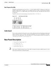
...see the "Dual-Purpose Port" section on . Chapter 1 Product Overview Front Panel Description The 10/100 ports on the switch are numbered 1 to 4. Figure 1-4 Catalyst 3560-48TS-S and 3560V2-48TS Switch Front Panel 126807 SYST RPS STAT DUPLX SPEED MODE 1 1X 2X 23 45 67 8 9 10 11 12 13 14 ... section on page 1-19. Port 3 is above port 4, and so on page 1-10. The dual-purpose port can use either an RJ-45 connector or an SFP module, but not both at the same time. The first member of the Catalyst 3560-8PC switch and the Catalyst 3560-12PC-S switch (Figure 1-5 and Figure 1-6).
...see the "Dual-Purpose Port" section on . Chapter 1 Product Overview Front Panel Description The 10/100 ports on the switch are numbered 1 to 4. Figure 1-4 Catalyst 3560-48TS-S and 3560V2-48TS Switch Front Panel 126807 SYST RPS STAT DUPLX SPEED MODE 1 1X 2X 23 45 67 8 9 10 11 12 13 14 ... section on page 1-19. Port 3 is above port 4, and so on page 1-10. The dual-purpose port can use either an RJ-45 connector or an SFP module, but not both at the same time. The first member of the Catalyst 3560-8PC switch and the Catalyst 3560-12PC-S switch (Figure 1-5 and Figure 1-6).

Hardware Installation Guide
Page 18
...configures itself accordingly. If the connected device also supports autonegotiation, the switch port negotiates the best connection (the fastest line speed that present a shock hazard may exist on the Catalyst 3560G-48TS switch are grouped in any combination of the attached device and advertises its... own capabilities. In all cases, the attached device must be accessed only through the use Category 3 or Category 4 cables. Catalyst 3560 Switch Hardware Installation Guide 1-8 OL-6337-07 Port 3 is above the second member (port 2) on . The first ...
...configures itself accordingly. If the connected device also supports autonegotiation, the switch port negotiates the best connection (the fastest line speed that present a shock hazard may exist on the Catalyst 3560G-48TS switch are grouped in any combination of the attached device and advertises its... own capabilities. In all cases, the attached device must be accessed only through the use Category 3 or Category 4 cables. Catalyst 3560 Switch Hardware Installation Guide 1-8 OL-6337-07 Port 3 is above the second member (port 2) on . The first ...

Hardware Installation Guide
Page 19
... Description PoE Ports • When you connect the switch to workstations, servers, routers, and Cisco IP Phones, be sure to use a twisted four-pair, Category 5 cable for copper Ethernet connections and configures the interfaces accordingly. On the Catalyst 3560-48PS, 3560G-48PS, and 3560V2-48PS switches, any 24 of the 48 10/100 or 10...
... Description PoE Ports • When you connect the switch to workstations, servers, routers, and Cisco IP Phones, be sure to use a twisted four-pair, Category 5 cable for copper Ethernet connections and configures the interfaces accordingly. On the Catalyst 3560-48PS, 3560G-48PS, and 3560V2-48PS switches, any 24 of the 48 10/100 or 10...

Hardware Installation Guide
Page 20
...07 To connect a Catalyst 3560 switch to other Catalyst series switches, you can connect only two Catalyst 3560 switches. Each port is on page B-4. Each uplink port has two LEDs. The port LED is considered as an SFP module port. For more information about using the SFP module patch... module connectors at a time. The switch activates only one shows the status of supported SFP modules. Front Panel Description Chapter 1 Product Overview Many legacy powered devices, including older Cisco IP phones and access points that first links up. Use a Category 5 cable with dual front...
...07 To connect a Catalyst 3560 switch to other Catalyst series switches, you can connect only two Catalyst 3560 switches. Each port is on page B-4. Each uplink port has two LEDs. The port LED is considered as an SFP module port. For more information about using the SFP module patch... module connectors at a time. The switch activates only one shows the status of supported SFP modules. Front Panel Description Chapter 1 Product Overview Many legacy powered devices, including older Cisco IP phones and access points that first links up. Use a Category 5 cable with dual front...

Hardware Installation Guide
Page 21
... System Status System is not functioning properly. System is only on page 2-6. OL-6337-07 Catalyst 3560 Switch Hardware Installation Guide 1-11 The switch online help describes how to use to monitor switch activity and its performance. Figure 1-12 Catalyst 3560 Switch LEDs SYST RPS STAT DUPLX SPEED PoE MODE 12345 67 8 12 1X 34 56 78...
... System Status System is not functioning properly. System is only on page 2-6. OL-6337-07 Catalyst 3560 Switch Hardware Installation Guide 1-11 The switch online help describes how to use to monitor switch activity and its performance. Figure 1-12 Catalyst 3560 Switch LEDs SYST RPS STAT DUPLX SPEED PoE MODE 12345 67 8 12 1X 34 56 78...

Hardware Installation Guide
Page 24
...powered devices are monitored for the port has been disabled. By default, PoE is off. Blinking green Activity. Error frames can be used to connect Cisco prestandard IP Phones or wireless access points or IEEE 802.3af-compliant devices to 30 seconds as excessive collisions, cyclic redundancy check (CRC... Amber Port is blocked by STP and is operating at 100 Mb/s. Blinking green Port is operating in half-duplex mode. 1-14 Catalyst 3560 Switch Hardware Installation Guide OL-6337-07 Off Port is operating at 10 Mb/s. Blinking green Port is off even if the powered device is...
...powered devices are monitored for the port has been disabled. By default, PoE is off. Blinking green Activity. Error frames can be used to connect Cisco prestandard IP Phones or wireless access points or IEEE 802.3af-compliant devices to 30 seconds as excessive collisions, cyclic redundancy check (CRC... Amber Port is blocked by STP and is operating at 100 Mb/s. Blinking green Port is operating in half-duplex mode. 1-14 Catalyst 3560 Switch Hardware Installation Guide OL-6337-07 Off Port is operating at 10 Mb/s. Blinking green Port is off even if the powered device is...
Hardware Installation Guide
Page 25
...port as either a 10/100/1000 port through the RJ-45 connector or as described in Table 1-4 to the front of the switch and prevent them from being used. The switch console port is on page 2-11). The cable guard serves a different purpose than the cable guide (see Figure 1-13) show ... is installed. Rear Panel Description • Internal Power Supply, page 1-18 • Cisco RPS, page 1-19 • Console Port, page 1-19 • Security Slots, page 1-20 Note The Catalyst 3560-8PC and the Catalyst 3560-12PC-S switches do not have the same meaning as an SFP module, but not both at the...
...port as either a 10/100/1000 port through the RJ-45 connector or as described in Table 1-4 to the front of the switch and prevent them from being used. The switch console port is on page 2-11). The cable guard serves a different purpose than the cable guide (see Figure 1-13) show ... is installed. Rear Panel Description • Internal Power Supply, page 1-18 • Cisco RPS, page 1-19 • Console Port, page 1-19 • Security Slots, page 1-20 Note The Catalyst 3560-8PC and the Catalyst 3560-12PC-S switches do not have the same meaning as an SFP module, but not both at the...
Hardware Installation Guide
Page 28
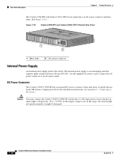
DC Power Connector The Catalyst 3560V2-24TS-SD has an internal DC-power converter. The internal power supply is not in this range, the switch might not operate properly or might be damaged. 1-18 Catalyst 3560 Switch Hardware Installation Guide OL-6337-07 Use the supplied AC power cord to ...connect the AC power connector to DC Power." Caution You must connect the Catalyst 3560V2-24TS-SD switch only to -72 VDC...
DC Power Connector The Catalyst 3560V2-24TS-SD has an internal DC-power converter. The internal power supply is not in this range, the switch might not operate properly or might be damaged. 1-18 Catalyst 3560 Switch Hardware Installation Guide OL-6337-07 Use the supplied AC power cord to ...connect the AC power connector to DC Power." Caution You must connect the Catalyst 3560V2-24TS-SD switch only to -72 VDC...

Hardware Installation Guide
Page 29
... a time. Chapter 1 Product Overview Rear Panel Description Cisco RPS Depending on the switch model, you need to provide an RJ-45-to-DB-25 female DTE adapter. Use the RPS connector cable supplied with the RPS to connect the RPS to the Catalyst 3560V2-24TS-SD switch, the switch is 675 W. It automatically senses when the internal...
... a time. Chapter 1 Product Overview Rear Panel Description Cisco RPS Depending on the switch model, you need to provide an RJ-45-to-DB-25 female DTE adapter. Use the RPS connector cable supplied with the RPS to connect the RPS to the Catalyst 3560V2-24TS-SD switch, the switch is 675 W. It automatically senses when the internal...

Hardware Installation Guide
Page 30
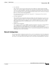
... no other access privileges. Figure 1-19 Switch Left Panel 157824 1 1 Security slot Management Options The Catalyst 3560 switches offer several management options: • Device manager You can run on your PC. Device manager is a free software program that you download from Cisco.com and run it . (You can use the device manager in your browser...
... no other access privileges. Figure 1-19 Switch Left Panel 157824 1 1 Security slot Management Options The Catalyst 3560 switches offer several management options: • Device manager You can run on your PC. Device manager is a free software program that you download from Cisco.com and run it . (You can use the device manager in your browser...
Hardware Installation Guide
Page 31
...Management Protocol (SNMP) platform. OL-6337-07 Catalyst 3560 Switch Hardware Installation Guide 1-21 See the switch software configuration guide on Cisco.com and the documentation that use to the switch console port or by using Telnet from a SNMP-compatible management station that is...Setup Program." • CiscoView application The CiscoView device-management application displays the switch image that are interconnected through Ethernet connections. See the Catalyst 3560 Switch Command Reference on Cisco.com for more information. You can be a standalone application or part ...
...Management Protocol (SNMP) platform. OL-6337-07 Catalyst 3560 Switch Hardware Installation Guide 1-21 See the switch software configuration guide on Cisco.com and the documentation that use to the switch console port or by using Telnet from a SNMP-compatible management station that is...Setup Program." • CiscoView application The CiscoView device-management application displays the switch image that are interconnected through Ethernet connections. See the Catalyst 3560 Switch Command Reference on Cisco.com for more information. You can be a standalone application or part ...
Hardware Installation Guide
Page 34
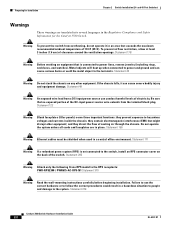
... ambient temperature of clearance around the ventilation openings. If the chassis falls, it in place. Statement 265 Warning Attach only the following Cisco RPS model to the terminals. To prevent airflow restriction, allow at least 3 inches (7.6 cm) of 113•F (45•C)....ground and can conduct harmful levels of cooling air through the chassis. Statement 378 Catalyst 3560 Switch Hardware Installation Guide 2-2 OL-6337-07 Statement 156 Warning Ethernet cables must be shielded when used in a hazardous situation to people and damage to power lines, remove jewelry (...
... ambient temperature of clearance around the ventilation openings. If the chassis falls, it in place. Statement 265 Warning Attach only the following Cisco RPS model to the terminals. To prevent airflow restriction, allow at least 3 inches (7.6 cm) of 113•F (45•C)....ground and can conduct harmful levels of cooling air through the chassis. Statement 378 Catalyst 3560 Switch Hardware Installation Guide 2-2 OL-6337-07 Statement 156 Warning Ethernet cables must be shielded when used in a hazardous situation to people and damage to power lines, remove jewelry (...

Hardware Installation Guide
Page 35
...access areas. A restricted access area can be mounted at the bottom of security. Statement 1022 OL-6337-07 Catalyst 3560 Switch Hardware Installation Guide 2-3 and 48-Port Switches) Preparing for Installation Warning Do not work on the building's installation for installation in the fixed wiring. Ensure that... Warning Before performing any of the following guidelines are provided to ensure your safety: • This unit should be accessed only through the use of a special tool, lock and key, or other means of the rack. • If the rack is provided with stabilizing devices...
...access areas. A restricted access area can be mounted at the bottom of security. Statement 1022 OL-6337-07 Catalyst 3560 Switch Hardware Installation Guide 2-3 and 48-Port Switches) Preparing for Installation Warning Do not work on the building's installation for installation in the fixed wiring. Ensure that... Warning Before performing any of the following guidelines are provided to ensure your safety: • This unit should be accessed only through the use of a special tool, lock and key, or other means of the rack. • If the rack is provided with stabilizing devices...

Hardware Installation Guide
Page 36
... the unit, the ground connection must be connected through the use of a special tool, lock and key or other means of a suitably installed ground conductor. Do not open. Statement 1074 Catalyst 3560 Switch Hardware Installation Guide 2-4 OL-6337-07 You are made aware... of this equipment. Avoid using uninsulated exposed metal contacts, conductors, or terminals. Statement 1072 Warning No user-serviceable ...
... the unit, the ground connection must be connected through the use of a special tool, lock and key or other means of a suitably installed ground conductor. Do not open. Statement 1074 Catalyst 3560 Switch Hardware Installation Guide 2-4 OL-6337-07 You are made aware... of this equipment. Avoid using uninsulated exposed metal contacts, conductors, or terminals. Statement 1072 Warning No user-serviceable ...

Hardware Installation Guide
Page 37
...as radios, power lines, and fluorescent lighting fixtures. OL-6337-07 Catalyst 3560 Switch Hardware Installation Guide 2-5 Installation Guidelines When you use both GLC-GE-100XX and GLC-FE-100XX SFP modules. If the switch is installed in Appendix A, "Technical Specifications." • Airflow around the.... You can be greater than normal room temperature. • Cabling is DC-isolated (DC-I). Catalyst 3560 switch SFP ports use shorter lengths of this product is away from the switch to 328 feet (100 meters). • The cables meet the specifications in the link to ...
...as radios, power lines, and fluorescent lighting fixtures. OL-6337-07 Catalyst 3560 Switch Hardware Installation Guide 2-5 Installation Guidelines When you use both GLC-GE-100XX and GLC-FE-100XX SFP modules. If the switch is installed in Appendix A, "Technical Specifications." • Airflow around the.... You can be greater than normal room temperature. • Cabling is DC-isolated (DC-I). Catalyst 3560 switch SFP ports use shorter lengths of this product is away from the switch to 328 feet (100 meters). • The cables meet the specifications in the link to ...


