
Hardware Installation Guide
Page 4
...Slots 2-17 Inserting and Removing the SFP Module Patch Cable 2-18 10/100 or 10/100/1000 Ports 2-19 Connecting the Switch to Compatible Devices 2-20 Connecting to 10BASE-T or 100BASE-TX Devices 2-20 Connecting to Fiber-Optic ...SFP Modules from the Switch 2-8 Attaching Brackets to the Catalyst 3560 Switch 2-8 Mounting the Switch in a Rack 2-10 Attaching the Cable Guide 2-11 Wall-Mounting 2-12 Attaching the Brackets to Go Next 2-24 Switch Installation (8- Contents 2 C H A P T E R 3 C H A P T E R Network Configurations 1-21 Switch Installation (24- and 48-Port Switches) 2-1 Preparing for ...
...Slots 2-17 Inserting and Removing the SFP Module Patch Cable 2-18 10/100 or 10/100/1000 Ports 2-19 Connecting the Switch to Compatible Devices 2-20 Connecting to 10BASE-T or 100BASE-TX Devices 2-20 Connecting to Fiber-Optic ...SFP Modules from the Switch 2-8 Attaching Brackets to the Catalyst 3560 Switch 2-8 Mounting the Switch in a Rack 2-10 Attaching the Cable Guide 2-11 Wall-Mounting 2-12 Attaching the Brackets to Go Next 2-24 Switch Installation (8- Contents 2 C H A P T E R 3 C H A P T E R Network Configurations 1-21 Switch Installation (24- and 48-Port Switches) 2-1 Preparing for ...

Hardware Installation Guide
Page 11
...Catalyst switch. For power redundancy, all but the Catalyst 3560 8- These topics are hot-swappable. Product Overview 1 C H A P T E R The Catalyst 3560 switch-also referred to as the switch-is an Ethernet switch to which you might deploy the switch. and 48-port Catalyst 3560 switches can connect devices like workstations, Cisco Wireless Access Points, Cisco... Options, page 1-20 Setting Up the Switch See the Catalyst 3560 Switch Getting Started Guide for examples of the Catalyst 3560 switch. Features The 24- See the switch software configuration guide for instructions on how ...
...Catalyst switch. For power redundancy, all but the Catalyst 3560 8- These topics are hot-swappable. Product Overview 1 C H A P T E R The Catalyst 3560 switch-also referred to as the switch-is an Ethernet switch to which you might deploy the switch. and 48-port Catalyst 3560 switches can connect devices like workstations, Cisco Wireless Access Points, Cisco... Options, page 1-20 Setting Up the Switch See the Catalyst 3560 Switch Getting Started Guide for examples of the Catalyst 3560 switch. Features The 24- See the switch software configuration guide for instructions on how ...

Hardware Installation Guide
Page 12
... 1-1 Catalyst 3560 Switch Model Descriptions Switch Model Description FastEthernet Catalyst 3560-24PS 24 10/100 Power over Ethernet (PoE) ports and 2 small form-factor pluggable (SFP) module slots Catalyst 3560-24TS-S 24 10/100 ports and 2 SFP module slots Catalyst 3560-48PS 48 10/100 PoE ports and 4 SFP module slots Catalyst 3560-48TS-S 48 10/100 ports and 4 SFP module slots Catalyst 3560V2-24PS 24...
... 1-1 Catalyst 3560 Switch Model Descriptions Switch Model Description FastEthernet Catalyst 3560-24PS 24 10/100 Power over Ethernet (PoE) ports and 2 small form-factor pluggable (SFP) module slots Catalyst 3560-24TS-S 24 10/100 ports and 2 SFP module slots Catalyst 3560-48PS 48 10/100 PoE ports and 4 SFP module slots Catalyst 3560-48TS-S 48 10/100 ports and 4 SFP module slots Catalyst 3560V2-24PS 24...

Hardware Installation Guide
Page 13
...Purpose Port, page 1-10 • LEDs, page 1-11 • Cable Guard, page 1-15 Fast Ethernet Switch Front Panel Descriptions • Catalyst 3560-24PS and 3560V2-24PS Switch Front Panel, Figure 1-1 on page 1-3 • Catalyst 3560-24TS-S, 3560V2-24TS, and 3560V2-24TS-SD Switch Front Panel, Figure 1-2 on page 1-4 • Catalyst 3560-48PS and 3560V2-48PS Switch Front ...56 78 9 10 11 12 11X 2X 12X 13 14 13X 15 16 17 18 19 20 21 22 23 24 Catalyst 3560 SERIES PoE-24 23X 14X 24X 1 2 1 2 1 10/100 PoE ports 2 SFP module slots Catalyst 3560 Switch Hardware Installation Guide 1-3
...Purpose Port, page 1-10 • LEDs, page 1-11 • Cable Guard, page 1-15 Fast Ethernet Switch Front Panel Descriptions • Catalyst 3560-24PS and 3560V2-24PS Switch Front Panel, Figure 1-1 on page 1-3 • Catalyst 3560-24TS-S, 3560V2-24TS, and 3560V2-24TS-SD Switch Front Panel, Figure 1-2 on page 1-4 • Catalyst 3560-48PS and 3560V2-48PS Switch Front ...56 78 9 10 11 12 11X 2X 12X 13 14 13X 15 16 17 18 19 20 21 22 23 24 Catalyst 3560 SERIES PoE-24 23X 14X 24X 1 2 1 2 1 10/100 PoE ports 2 SFP module slots Catalyst 3560 Switch Hardware Installation Guide 1-3

Hardware Installation Guide
Page 14
... in Figure 1-2. Figure 1-2 Catalyst 3560-24TS-S, 3560V2-24TS, and 3560V2-24TS-SD Switch Front Panel 126808 SYST RPS STAT DUPLX SPEED MODE 12 1X 34 56 78 9 10 11 12 11X 2X 12X 13 14 13X 15 16 17 18 19 20 21 22 23 24 23X Catalyst 3560 SERIES 14X 24X 1 2 1 2 1 10/100 ports 2 SFP module slots...
... in Figure 1-2. Figure 1-2 Catalyst 3560-24TS-S, 3560V2-24TS, and 3560V2-24TS-SD Switch Front Panel 126808 SYST RPS STAT DUPLX SPEED MODE 12 1X 34 56 78 9 10 11 12 11X 2X 12X 13 14 13X 15 16 17 18 19 20 21 22 23 24 23X Catalyst 3560 SERIES 14X 24X 1 2 1 2 1 10/100 ports 2 SFP module slots...

Hardware Installation Guide
Page 15
... console port, see the "Dual-Purpose Port" section on . Figure 1-5 Catalyst 3560-8PC Switch Front Panel SYST STAT DPLX SPD MODE CONSOLE 1x 2x 3x 4x 5x 6x 7x 8x Catalyst 2960 Series 1 157822 1 2 3 1 Console port 2 10/100 PoE ports 3 Dual-purpose port OL-6337-07 Catalyst 3560 Switch Hardware ...port, see the "Console Port" section on the switch are grouped in Figure 1-4. Figure 1-4 Catalyst 3560-48TS-S and 3560V2-48TS Switch Front Panel 126807 SYST RPS STAT DUPLX SPEED MODE 1 1X 2X 23 45 67 8 9 10 11 12 13 14 15 16 17 15X 17X 18 19 20 21 22 23 24...
... console port, see the "Dual-Purpose Port" section on . Figure 1-5 Catalyst 3560-8PC Switch Front Panel SYST STAT DPLX SPD MODE CONSOLE 1x 2x 3x 4x 5x 6x 7x 8x Catalyst 2960 Series 1 157822 1 2 3 1 Console port 2 10/100 PoE ports 3 Dual-purpose port OL-6337-07 Catalyst 3560 Switch Hardware ...port, see the "Console Port" section on the switch are grouped in Figure 1-4. Figure 1-4 Catalyst 3560-48TS-S and 3560V2-48TS Switch Front Panel 126807 SYST RPS STAT DUPLX SPEED MODE 1 1X 2X 23 45 67 8 9 10 11 12 13 14 15 16 17 15X 17X 18 19 20 21 22 23 24...

Hardware Installation Guide
Page 16
...Catalyst 3560 SERIESPoE-12 1 3 1 Console port 2 10/100 PoE ports 3 Dual-purpose port Gigabit Ethernet Switch Front Panel Descriptions • Catalyst 3560G-24PS Switch Front Panel, Figure 1-7 on page 1-6 • Catalyst 3560G-24TS Switch Front Panel, Figure 1-8 on page 1-7 • Catalyst 3560G-48PS Switch Front Panel, Figure 1-9 on page 1-7 • Catalyst 3560G-48TS Switch...15 16 17 18 19 20 21 22 23 24 Catalyst 3560G SERIES PoE-24 23X 25 14X 27 24X 26 28 1 2 1 10/100/1000 ports 2 SFP module slots Catalyst 3560 Switch Hardware Installation Guide 1-6 OL-6337-07 The SFP ...
...Catalyst 3560 SERIESPoE-12 1 3 1 Console port 2 10/100 PoE ports 3 Dual-purpose port Gigabit Ethernet Switch Front Panel Descriptions • Catalyst 3560G-24PS Switch Front Panel, Figure 1-7 on page 1-6 • Catalyst 3560G-24TS Switch Front Panel, Figure 1-8 on page 1-7 • Catalyst 3560G-48PS Switch Front Panel, Figure 1-9 on page 1-7 • Catalyst 3560G-48TS Switch...15 16 17 18 19 20 21 22 23 24 Catalyst 3560G SERIES PoE-24 23X 25 14X 27 24X 26 28 1 2 1 10/100/1000 ports 2 SFP module slots Catalyst 3560 Switch Hardware Installation Guide 1-6 OL-6337-07 The SFP ...

Hardware Installation Guide
Page 17
... the second member (port 2) on the Catalyst 3560G-48PS switch are numbered 49 to 28. Figure 1-8 Catalyst 3560G-24TS Switch Front Panel 119677 SYST RPS STAT DUPLX SPEED MODE 12 1X 34 56 78 9 10 11 12 11X 2X 12X 13 14 13X 15 16 17 18 19 20 21 22 23 24 23X Catalyst 3560G SERIES 25... 14X 27 24X 26 28 1 2 1 10/100/1000 ports 2 SFP module slots...
... the second member (port 2) on the Catalyst 3560G-48PS switch are numbered 49 to 28. Figure 1-8 Catalyst 3560G-24TS Switch Front Panel 119677 SYST RPS STAT DUPLX SPEED MODE 12 1X 34 56 78 9 10 11 12 11X 2X 12X 13 14 13X 15 16 17 18 19 20 21 22 23 24 23X Catalyst 3560G SERIES 25... 14X 27 24X 26 28 1 2 1 10/100/1000 ports 2 SFP module slots...

Hardware Installation Guide
Page 18
... are made aware of the hazard. Figure 1-10 Catalyst 3560G-48TS Switch Front Panel 119675 SYST RPS STAT DUPLX SPEED MODE 1 1X 2X 23 45 67 8 9 10 11 12 13 14 15 16 17 15X 17X 18 19 20 21 22 23 24 25 26 27 28 29 30 31 32 16X...supports it) and configures itself accordingly. A restricted access area can set the 10/100/1000 ports to 10 or 100 Mb/s. Front Panel Description Chapter 1 Product Overview The 10/100/1000 ports on the Catalyst 3560G-48TS switch are made using such interconnection methods, unless the exposed metal parts are located within a restricted access...
... are made aware of the hazard. Figure 1-10 Catalyst 3560G-48TS Switch Front Panel 119675 SYST RPS STAT DUPLX SPEED MODE 1 1X 2X 23 45 67 8 9 10 11 12 13 14 15 16 17 15X 17X 18 19 20 21 22 23 24 25 26 27 28 29 30 31 32 16X...supports it) and configures itself accordingly. A restricted access area can set the 10/100/1000 ports to 10 or 100 Mb/s. Front Panel Description Chapter 1 Product Overview The 10/100/1000 ports on the Catalyst 3560G-48TS switch are made using such interconnection methods, unless the exposed metal parts are located within a restricted access...

Hardware Installation Guide
Page 19
...when an IP phone or an access point is connected. On the Catalyst 3560-48PS, 3560G-48PS, and 3560V2-48PS switches, any 24 of the 48 10/100 or 10/100/1000 ports delivers 15.4 W of PoE, or any combination of the ports delivers an average of 7.7 W of PoE at the same time...or reestablish link with IEEE 802.3af and Cisco prestandard PoE support for Cisco IP Phones and Cisco Aironet Access Points. • Each of the Catalyst 3560-8PC, 3560-12PC-S, 3560-24PS, and 3560V2-24PS switch 10/100 ports or the Catalyst 3560G-24PS switch 10/100/1000 ports deliver up to enable the automatic medium-...
...when an IP phone or an access point is connected. On the Catalyst 3560-48PS, 3560G-48PS, and 3560V2-48PS switches, any 24 of the 48 10/100 or 10/100/1000 ports delivers 15.4 W of PoE, or any combination of the ports delivers an average of 7.7 W of PoE at the same time...or reestablish link with IEEE 802.3af and Cisco prestandard PoE support for Cisco IP Phones and Cisco Aironet Access Points. • Each of the Catalyst 3560-8PC, 3560-12PC-S, 3560-24PS, and 3560V2-24PS switch 10/100 ports or the Catalyst 3560G-24PS switch 10/100/1000 ports deliver up to enable the automatic medium-...
Hardware Installation Guide
Page 33
... SFP Module Patch Cable, page 2-18 • 10/100 or 10/100/1000 Ports, page 2-19 • Connecting the Switch to Compatible Devices, page 2-20 • Where to the switch. and 48-port switches, including how to install the Catalyst 3560 24- and 48-Port Switches) This chapter describes how to interpret the power-on self-test (POST) that...
... SFP Module Patch Cable, page 2-18 • 10/100 or 10/100/1000 Ports, page 2-19 • Connecting the Switch to Compatible Devices, page 2-20 • Where to the switch. and 48-port switches, including how to install the Catalyst 3560 24- and 48-Port Switches) This chapter describes how to interpret the power-on self-test (POST) that...
Hardware Installation Guide
Page 34
... hardware or to follow the correct procedures could result in the Regulatory Compliance and Safety Information for Installation Chapter 2 Switch Installation (24- Preparing for the Catalyst 3560 Switch. To prevent airflow restriction, allow at least 3 inches (7.6 cm) of 113•F (45•C). Metal ...the following Cisco RPS model to hazardous voltages and currents inside the chassis; Statement 171 Warning If a redundant power system (RPS) is connected to the switch, install an RPS connector cover on the back of cooling air through the chassis. and 48-Port Switches) Warnings...
... hardware or to follow the correct procedures could result in the Regulatory Compliance and Safety Information for Installation Chapter 2 Switch Installation (24- Preparing for the Catalyst 3560 Switch. To prevent airflow restriction, allow at least 3 inches (7.6 cm) of 113•F (45•C). Metal ...the following Cisco RPS model to hazardous voltages and currents inside the chassis; Statement 171 Warning If a redundant power system (RPS) is connected to the switch, install an RPS connector cover on the back of cooling air through the chassis. and 48-Port Switches) Warnings...

Hardware Installation Guide
Page 35
... injury when mounting or servicing this unit in a partially filled rack, load the rack from the DC circuit. Chapter 2 Switch Installation (24- Statement 1006 Warning Class 1 laser product. Statement 1017 Warning The plug-socket combination must be accessed only through the use of.... Statement 1019 Warning A readily accessible two-poled disconnect device must be mounted at the bottom of lightning activity. and 48-Port Switches) Preparing for Installation Warning Do not work on the building's installation for installation in the fixed wiring. The following procedures,...
... injury when mounting or servicing this unit in a partially filled rack, load the rack from the DC circuit. Chapter 2 Switch Installation (24- Statement 1006 Warning Class 1 laser product. Statement 1017 Warning The plug-socket combination must be accessed only through the use of.... Statement 1019 Warning A readily accessible two-poled disconnect device must be mounted at the bottom of lightning activity. and 48-Port Switches) Preparing for Installation Warning Do not work on the building's installation for installation in the fixed wiring. The following procedures,...

Hardware Installation Guide
Page 36
...the equipment is available. Use the statement number provided at the end of a suitably installed ground conductor. Statement 1074 Catalyst 3560 Switch Hardware Installation Guide 2-4 OL-6337-07 Contact the appropriate electrical inspection authority or an electrician if you work on Power...(24- Statement 1044 Warning When installing or replacing the unit, the ground connection must be accessed only through an approved network termination unit with local and national electrical codes. Statement 1071 Warning Voltages that suitable grounding is installed, the following ports ...
...the equipment is available. Use the statement number provided at the end of a suitably installed ground conductor. Statement 1074 Catalyst 3560 Switch Hardware Installation Guide 2-4 OL-6337-07 Contact the appropriate electrical inspection authority or an electrician if you work on Power...(24- Statement 1044 Warning When installing or replacing the unit, the ground connection must be accessed only through an approved network termination unit with local and national electrical codes. Statement 1071 Warning Voltages that suitable grounding is installed, the following ports ...

Hardware Installation Guide
Page 37
... lengths from sources of this product is sufficient for unrestricted cabling. - OL-6337-07 Catalyst 3560 Switch Hardware Installation Guide 2-5 Chapter 2 Switch Installation (24- and 48-Port Switches) Statement 371-Power Cable and AC Adapter Preparing for the Catalyst 3560 switch. Caution To comply with the Telcordia GR-1089 Network Equipment Building Systems (NEBS) standard for electromagnetic compatibility...
... lengths from sources of this product is sufficient for unrestricted cabling. - OL-6337-07 Catalyst 3560 Switch Hardware Installation Guide 2-5 Chapter 2 Switch Installation (24- and 48-Port Switches) Statement 371-Power Cable and AC Adapter Preparing for the Catalyst 3560 switch. Caution To comply with the Telcordia GR-1089 Network Equipment Building Systems (NEBS) standard for electromagnetic compatibility...

Hardware Installation Guide
Page 38
... 370 Catalyst 3560 Switch Hardware Installation Guide 2-6 OL-6337-07 Verifying Switch Operation Chapter 2 Switch Installation (24- However, these fans and blowers can result in an environment as free as possible from construction activities). Set the RPS to run Express Setup. Warning Attach only the following Cisco RPS model to rack-mount the switch. and 48-Port Switches) When...
... 370 Catalyst 3560 Switch Hardware Installation Guide 2-6 OL-6337-07 Verifying Switch Operation Chapter 2 Switch Installation (24- However, these fans and blowers can result in an environment as free as possible from construction activities). Set the RPS to run Express Setup. Warning Attach only the following Cisco RPS model to rack-mount the switch. and 48-Port Switches) When...
Hardware Installation Guide
Page 39
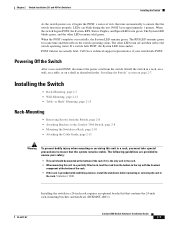
...24-inch rack-mounting brackets and hardware (RCKMNT-1RU=). or Shelf- OL-6337-07 Catalyst 3560 Switch Hardware Installation Guide 2-7 Powering Off the Switch After a successful POST, disconnect the power cord from the Switch, page 2-8 • Attaching Brackets to the Catalyst 3560 Switch, page 2-8 • Mounting the Switch... • Table- and 48-Port Switches) Installing the Switch As the switch powers on page 2-7. Chapter 2 Switch Installation (24- Install the switch in a rack, on a wall, on a table, or on a shelf as described in the "Installing the Switch" section on , it is ...
...24-inch rack-mounting brackets and hardware (RCKMNT-1RU=). or Shelf- OL-6337-07 Catalyst 3560 Switch Hardware Installation Guide 2-7 Powering Off the Switch After a successful POST, disconnect the power cord from the Switch, page 2-8 • Attaching Brackets to the Catalyst 3560 Switch, page 2-8 • Mounting the Switch... • Table- and 48-Port Switches) Installing the Switch As the switch powers on page 2-7. Chapter 2 Switch Installation (24- Install the switch in a rack, on a wall, on a table, or on a shelf as described in the "Installing the Switch" section on , it is ...

Hardware Installation Guide
Page 40
...Port Switches) Removing Screws from the Switch Before you install the switch in a rack, remove the switch chassis screws (see Figure 2-1.) Figure 2-1 Removing Screws from the Catalyst 3560 Switch 97916 40 41 42 43 44 45 46 47 48 47X Catalyst 3560 SERIES PoE-48 1 3 48X 2 4 Attaching Brackets to the Catalyst 3560 Switch...12 13 14 15 16 15X 2X 16X 1 Phillips flat-head screws 97917 Catalyst 3560 Switch Hardware Installation Guide 2-8 OL-6337-07 Installing the Switch Chapter 2 Switch Installation (24- Figure 2-2 through Figure 2-7 show how to attach each type bracket to...
...Port Switches) Removing Screws from the Switch Before you install the switch in a rack, remove the switch chassis screws (see Figure 2-1.) Figure 2-1 Removing Screws from the Catalyst 3560 Switch 97916 40 41 42 43 44 45 46 47 48 47X Catalyst 3560 SERIES PoE-48 1 3 48X 2 4 Attaching Brackets to the Catalyst 3560 Switch...12 13 14 15 16 15X 2X 16X 1 Phillips flat-head screws 97917 Catalyst 3560 Switch Hardware Installation Guide 2-8 OL-6337-07 Installing the Switch Chapter 2 Switch Installation (24- Figure 2-2 through Figure 2-7 show how to attach each type bracket to...
Hardware Installation Guide
Page 41
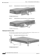
... 2 Switch Installation (24- and 48-Port Switches) Installing the Switch Figure 2-3 1 Attaching Brackets for 24-Inch Racks to a Catalyst 3560 Switch, Front Panel Forward 1 Phillips flat-head screws SYST RPS STAT DUPLX SPEED PoE MODE 1 1X 23 45 67 8 9 10 11 12 13 14 15 16 15X 2X 16X 97918 Figure 2-4 Attaching Brackets for 19-Inch Racks to a Catalyst...
... 2 Switch Installation (24- and 48-Port Switches) Installing the Switch Figure 2-3 1 Attaching Brackets for 24-Inch Racks to a Catalyst 3560 Switch, Front Panel Forward 1 Phillips flat-head screws SYST RPS STAT DUPLX SPEED PoE MODE 1 1X 23 45 67 8 9 10 11 12 13 14 15 16 15X 2X 16X 97918 Figure 2-4 Attaching Brackets for 19-Inch Racks to a Catalyst...
Hardware Installation Guide
Page 42
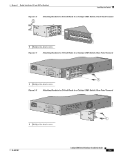
Installing the Switch Chapter 2 Switch Installation (24- and 48-Port Switches) Figure 2-6 Attaching Brackets for 19-Inch Telco Racks to a Catalyst 3560 Switch 97921 40 41 42 43 44 45 46 47 48 47X Catalyst 3560 SERIES PoE-48 1 3 48X 2 4 1 1 Phillips flat-head screws Figure 2-7 Attaching Brackets for 24-Inch Telco Racks to a Catalyst 3560 Switch 97922 40 41 42 43 44...
Installing the Switch Chapter 2 Switch Installation (24- and 48-Port Switches) Figure 2-6 Attaching Brackets for 19-Inch Telco Racks to a Catalyst 3560 Switch 97921 40 41 42 43 44 45 46 47 48 47X Catalyst 3560 SERIES PoE-48 1 3 48X 2 4 1 1 Phillips flat-head screws Figure 2-7 Attaching Brackets for 24-Inch Telco Racks to a Catalyst 3560 Switch 97922 40 41 42 43 44...


