Hardware Installation Guide
Page 5
... 4-2 Ethernet and Fiber Cables 4-3 Link Status 4-3 Transceiver Module Port Issues 4-3 Port and Interface Settings 4-4 Ping the End Device 4-4 Spanning Tree Loops 4-4 Monitor Switch Performance 4-4 Speed, Duplex, and Autonegotiation 4-4 Autonegotiation and Network Interface Cards 4-5 Cabling Distance 4-5 Clearing the Switch IP Address and Configuration 4-5 Locating the Switch Serial Number 4-6 Contents OL-6337-07 Catalyst 3560 Switch Hardware Installation Guide v
... 4-2 Ethernet and Fiber Cables 4-3 Link Status 4-3 Transceiver Module Port Issues 4-3 Port and Interface Settings 4-4 Ping the End Device 4-4 Spanning Tree Loops 4-4 Monitor Switch Performance 4-4 Speed, Duplex, and Autonegotiation 4-4 Autonegotiation and Network Interface Cards 4-5 Cabling Distance 4-5 Clearing the Switch IP Address and Configuration 4-5 Locating the Switch Serial Number 4-6 Contents OL-6337-07 Catalyst 3560 Switch Hardware Installation Guide v

Hardware Installation Guide
Page 24
...switch port is operating in half duplex. Amber PoE for a link-fault indication. Blinking green Activity. Off Port is providing power. Port is not sending or receiving packets. Alternating green-amber Link fault. Blinking amber Port is blocked by Spanning Tree...powered device is off . Error frames can be used to connect Cisco prestandard IP Phones or wireless access points or IEEE 802.3af-compliant... PoE ports. Note When installed in half-duplex mode. 1-14 Catalyst 3560 Switch Hardware Installation Guide OL-6337-07 Green Alternating green and amber Blinking...
...switch port is operating in half duplex. Amber PoE for a link-fault indication. Blinking green Activity. Off Port is providing power. Port is not sending or receiving packets. Alternating green-amber Link fault. Blinking amber Port is blocked by Spanning Tree...powered device is off . Error frames can be used to connect Cisco prestandard IP Phones or wireless access points or IEEE 802.3af-compliant... PoE ports. Note When installed in half-duplex mode. 1-14 Catalyst 3560 Switch Hardware Installation Guide OL-6337-07 Green Alternating green and amber Blinking...
Hardware Installation Guide
Page 52
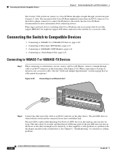
... 10BASE-T or 100BASE-TX Devices Step 1 When connecting to cabling problems. 2-20 Catalyst 3560 Switch Hardware Installation Guide OL-6337-07 The port LED is amber while Spanning Tree Protocol (STP) discovers the topology and searches for solutions to workstations, servers, routers, and Cisco IP Phones, connect a straight-through , twisted four-pair Category 5 cable. This...
... 10BASE-T or 100BASE-TX Devices Step 1 When connecting to cabling problems. 2-20 Catalyst 3560 Switch Hardware Installation Guide OL-6337-07 The port LED is amber while Spanning Tree Protocol (STP) discovers the topology and searches for solutions to workstations, servers, routers, and Cisco IP Phones, connect a straight-through , twisted four-pair Category 5 cable. This...

Hardware Installation Guide
Page 78
Contact your Cisco technical support representative if your switch does not pass POST. In these sections when troubleshooting switch connectivity problems: • Bad or Damaged Cable, page 4-2... the End Device, page 4-4 • Spanning Tree Loops, page 4-4 Bad or Damaged Cable Always look at the cable for marginal damage or failure. When the switch begins POST, the system LED slowly blinks..., good cable if necessary. • Look for the switch to ensure that runs automatically to complete POST. Catalyst 3560 Switch Hardware Installation Guide 4-2 OL-6337-07 It might connect ...
Contact your Cisco technical support representative if your switch does not pass POST. In these sections when troubleshooting switch connectivity problems: • Bad or Damaged Cable, page 4-2... the End Device, page 4-4 • Spanning Tree Loops, page 4-4 Bad or Damaged Cable Always look at the cable for marginal damage or failure. When the switch begins POST, the system LED slowly blinks..., good cable if necessary. • Look for the switch to ensure that runs automatically to complete POST. Catalyst 3560 Switch Hardware Installation Guide 4-2 OL-6337-07 It might connect ...
Hardware Installation Guide
Page 80
Spanning Tree Loops Spanning Tree Protocol (STP) loops can cause serious performance issues ...optic links. A broken fiber-optic cable, other side of the link, the link does not come up until you troubleshoot switch performance problems: • Speed, Duplex, and Autonegotiation, page 4-4 • Autonegotiation and Network Interface Cards, page 4-5 &#...aggressive mode, UDLD also detects unidirectional links caused by first pinging it from the neighbor. Catalyst 3560 Switch Hardware Installation Guide 4-4 OL-6337-07 Ping the End Device Verify the end device connection by one ...
Spanning Tree Loops Spanning Tree Protocol (STP) loops can cause serious performance issues ...optic links. A broken fiber-optic cable, other side of the link, the link does not come up until you troubleshoot switch performance problems: • Speed, Duplex, and Autonegotiation, page 4-4 • Autonegotiation and Network Interface Cards, page 4-5 &#...aggressive mode, UDLD also detects unidirectional links caused by first pinging it from the neighbor. Catalyst 3560 Switch Hardware Installation Guide 4-4 OL-6337-07 Ping the End Device Verify the end device connection by one ...

Hardware Installation Guide
Page 119
... link status 4-3 ping end device 4-4 port and interface settings 4-4 POST 4-1 spanning tree loops 4-4 speed, duplex, and autonegotiation 4-4 switch performance 4-4 troubleshooting spanning tree loops 4-4 W wall-mounting 24- and 12-port switches 3-17 warnings code compliance 2-4, 3-4 DC power C-6 defined i-vii ground connection ... 2-17 shelf-mounting 24- and 12-port switches) 3-2 Catalyst 3560 Switch Hardware Installation Guide IN-5 24- and 48-port switches 2-7, 2-11 8- and 48-port switches 2-12 8- and 48-port switches 2-15 8- and 12-port switches 3-16, 3-17 rear panel clearance 2-5, ...
... link status 4-3 ping end device 4-4 port and interface settings 4-4 POST 4-1 spanning tree loops 4-4 speed, duplex, and autonegotiation 4-4 switch performance 4-4 troubleshooting spanning tree loops 4-4 W wall-mounting 24- and 12-port switches 3-17 warnings code compliance 2-4, 3-4 DC power C-6 defined i-vii ground connection ... 2-17 shelf-mounting 24- and 12-port switches) 3-2 Catalyst 3560 Switch Hardware Installation Guide IN-5 24- and 48-port switches 2-7, 2-11 8- and 48-port switches 2-12 8- and 48-port switches 2-15 8- and 12-port switches 3-16, 3-17 rear panel clearance 2-5, ...
